
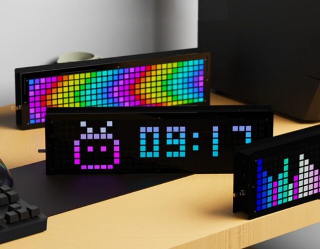
This week we share a mini but fully functional clock project, with RGB effects and temperature monitoring function.
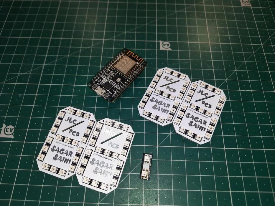
Step 1: Material Preparation
-
NodeMCU (ESP8266)
-
Custom PCB board
-
Connecting wires
-
Battery 5v
Concept
Use NodeMCU to display time and Arduino to monitor temperature; you can choose to change the display color every second.
The rated voltage of the mini LED is 3.0V to 5.5V, 16mA (per LED).
Our NodeMCU has a 3.3V voltage regulator, which can drive all LEDs normally.
Step 2: LED WS2812B 3030
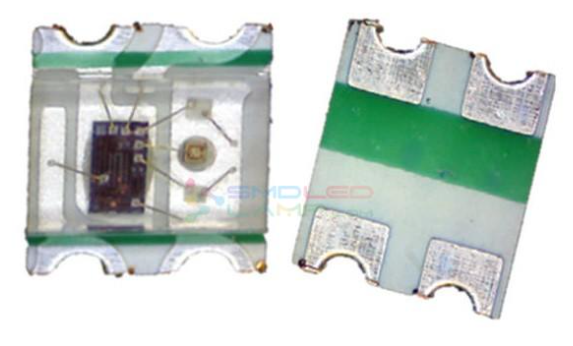
Here we use WS2812 NeoPixel Led, which comes with an integrated IC, allowing us to address each segment individually. Not only can the LEDs be addressed, but we can also change the color of each pixel (changing the numerical value of 0-255 (8-bit value)).
The LED has 4 pins, and additionally, these LEDs have data input and output functions, through which we can connect them together to display text or data.
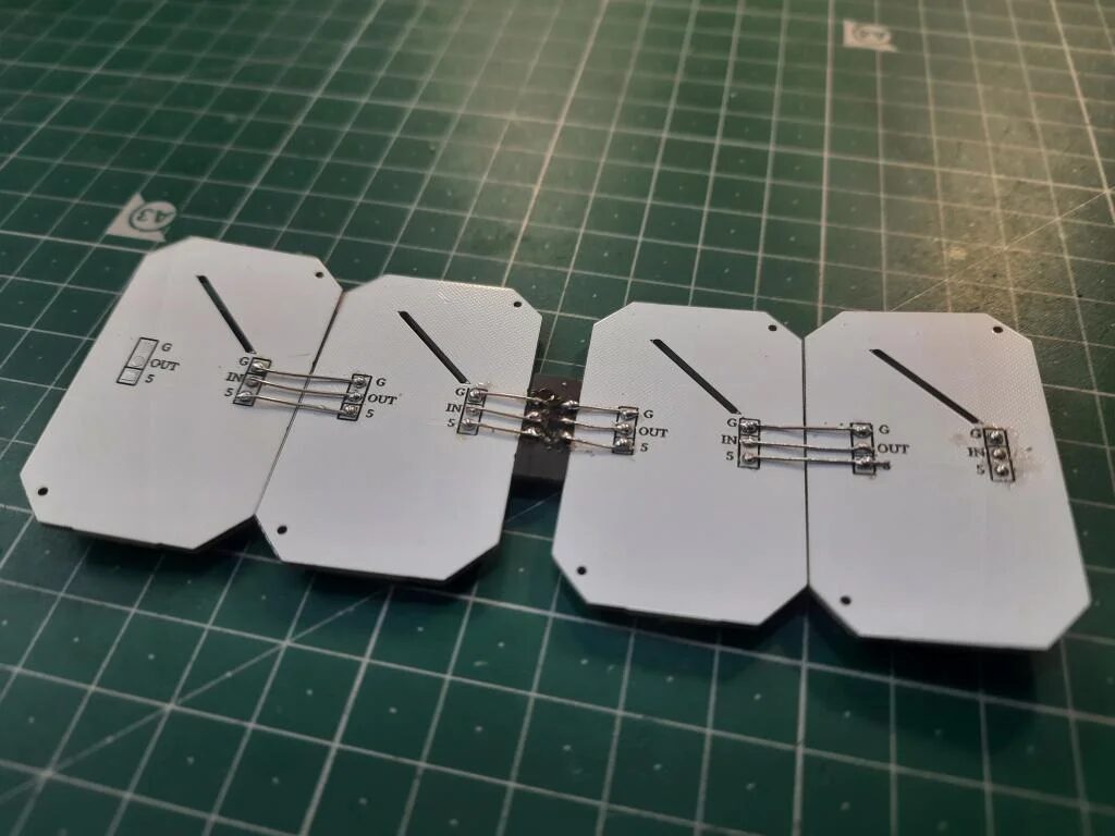
Step 3: Making with NeoPixel Led
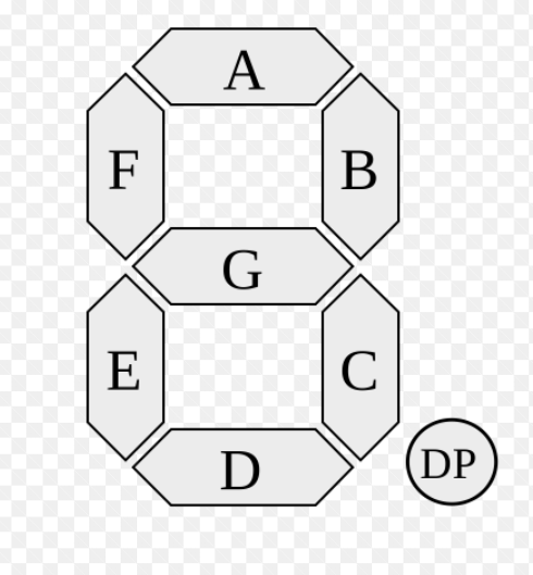
To make this panel, we can first take a close look at the actual LCD display. This way, we can replicate the segment arrangement and write code for it.
In the above figure, each segment is named A, B, C, D, E, F, G. To connect all segments, we use a method of series data and parallel power supply: all power lines, GND, and VCC are paralleled to all LEDs; data output is provided to the data input of the next LED in series; connect the Dout of the first panel to the Din of the second panel.
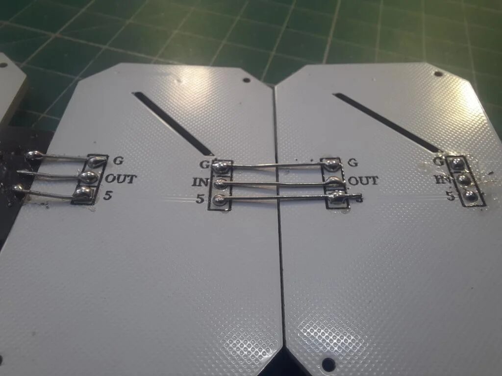
Step 4: Connection
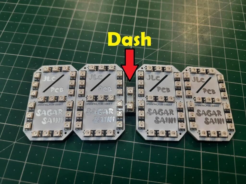
To connect the hour and minute panels, we place a small PCB board in between, which is the “Dash” in the above figure.
Step 5: NodeMCU/ESP8266
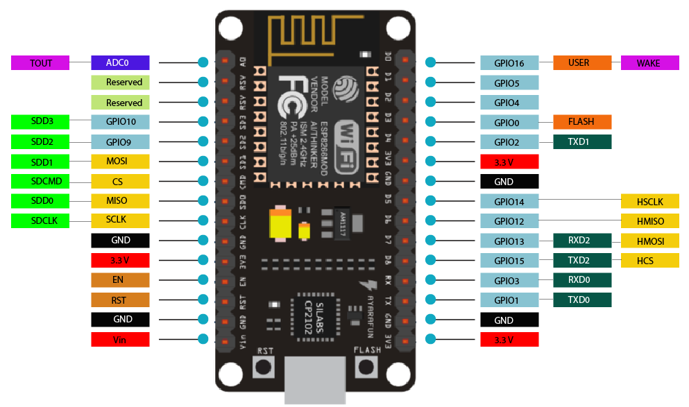
ESP8266 integrates a 32-bit Tensilica processor with standard digital peripheral interfaces.
ESP8266 has onboard Wi-Fi support, allowing it to adjust time via the Internet without any RTC (real-time clock) module. This reduces connections and makes the entire project a little simpler.
If you use the code below, you can add two extra functions to this 7-segment clock.
Step 6: Temperature and Humidity
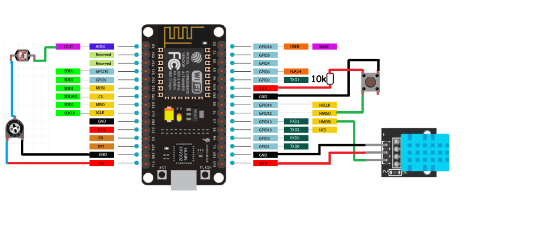
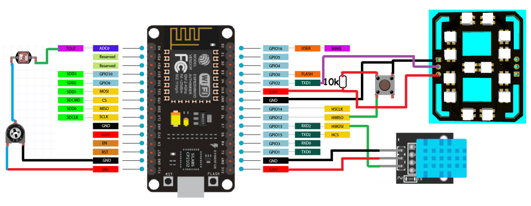
Add a DHT11 sensor to pin 13 and a tactile button to pin 12, so we can get the temperature value in Celsius or Fahrenheit on the screen.
Connect a 10k resistor from pin 12 of the button to 5V, and the other end to GND. That is, when the button pin is pulled to GND, the display will show the temperature reading.
If there is no temperature sensor, the code can still run normally, so if you want to keep it as simple as possible, you can skip these connections.
Step 7: Brightness Control
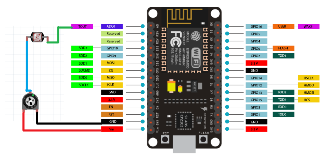
By creating a resistor divider network on pin A0, adding an LDR sensor with a 10k resistor, the brightness can change accordingly.
High brightness during the day, low brightness at night.
If you do not want adjustable brightness, the code below can also run normally without these sensors, maintaining default settings.
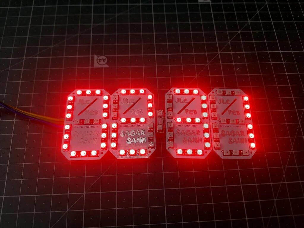
Step 8: 7-Segment Clock
I designed the circuit in EasyEDA, using 3 LEDs here. Therefore, a total of 21 LEDs are needed for each panel.
The underlying connection pins are made so that others cannot see the connections and wiring.
CPL, BOM, and Gerber files are in the GitHub repository:
https://github.com/halfstudents/ESP8266-Wi-Fi-based-7-Segment-Display-clock
Alternatively, you can also download it at the end of the article.
Step 9: Connection
Use the above schematic to connect NodeMCU.
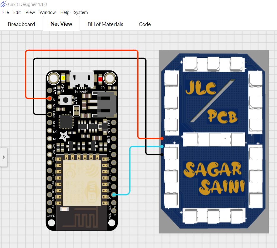
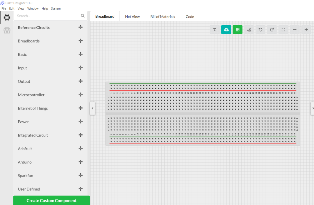
The software used here is Cirkit Designer, a very good software.
Usually, you can use this line diagram, breadboard circuit, and create some custom components when demonstrating at school. Additionally, it has recently added code compilation, BOM, and some new components.
Using Cirkit Designer, we can draw realistic circuit diagrams that are linked to the bill of materials, allowing seamless ordering of components in the circuit.
Available for Windows, Linux, and Mac; download link: https://www.cirkitstudio.com/download.html
Step 10: Code Part
-
First, initialize the code with libraries:
#include <esp8266wifi.h>
#include <adafruit_neopixel.h>
#include <wifiudp.h>
#include <ntpclient.h>
#include <timelib.h>
#include <dht.h>
#include <adafruit_sensor.h>
</adafruit_sensor.h></dht.h></timelib.h></ntpclient.h></wifiudp.h></adafruit_neopixel.h></esp8266wifi.h>-
Define all Pixels, I/O pins, and sensor pins:
#define PIXEL_PER_SEGMENT 3 // Number of LEDs in each Segment
#define PIXEL_DIGITS 4 // Number of connected Digits
#define PIXEL_PIN 2 // GPIO Pin
#define PIXEL_DASH 1 // Binary segment
#define LDR_PIN A0 // LDR pin
#define DHT_PIN 13 // DHT Sensor pin
#define BUTTON_PIN 12 // Button pin
-
Adjust time, using Wi-Fi to connect the Internet to ESP8266:
WiFi.begin(ssid, password);
Serial.print("Connecting.");
while ( WiFi.status() != WL_CONNECTED )
-
Time settings on Pixel:
void disp_Time() {
clearDisplay();
writeDigit(0, Hour / 10);
writeDigit(1, Hour % 10);
writeDigit(2, Minute / 10);
writeDigit(3, Minute % 10);
writeDigit(4, Second / 10);
writeDigit(5, Second % 10);
disp_Dash();
5) Color settings for the panel display:
if (index == 0 || index == 1 ) color = strip.Color(0, Brightness, 0);
if (index == 2 || index == 3 ) color = strip.Color(0, Brightness, 0);
if (index == 4 || index == 5 ) color = strip.Color(Brightness, 0, 0);
Complete code:
#include <esp8266wifi.h>
#include <adafruit_neopixel.h>
#include <wifiudp.h>
#include <ntpclient.h>
#include <timelib.h>
#include <dht.h>
#include <adafruit_sensor.h>

#define PIXEL_PER_SEGMENT  3     // Number of LEDs in each Segment
#define PIXEL_DIGITS       4     // Number of connected Digits
#define PIXEL_PIN          2     // GPIO Pin
#define PIXEL_DASH         1    // Binary segment

#define LDR_PIN       A0    // LDR pin
#define DHT_PIN       13    // DHT Sensor pin
#define BUTTON_PIN    12    // Button pin

// Uncomment the type of sensor in use
#define DHT_TYPE    DHT11     // DHT 11
//#define DHT_TYPE    DHT22     // DHT 22 (AM2302)
//#define DHT_TYPE    DHT21     // DHT 21 (AM2301)

#define TIME_FORMAT        12    // 12 = 12 hours format || 24 = 24 hours format

Adafruit_NeoPixel strip = Adafruit_NeoPixel((PIXEL_PER_SEGMENT * 7 * PIXEL_DIGITS) + (PIXEL_DASH * 2), PIXEL_PIN, NEO_GRB + NEO_KHZ800);
DHT dht(DHT_PIN, DHT_TYPE);

// set Wi-Fi SSID and password
const char *ssid     = "Hackster";
const char *password = "*************";

WiFiUDP ntpUDP;
// 'time.nist.gov' is used (default server) with +1 hour offset (3600 seconds) 60 seconds (60000 milliseconds) update interval
NTPClient timeClient(ntpUDP, "time.nist.gov", 19800, 60000); //GMT+5:30 : 5*3600+30*60=19800

int period = 2000;   //Update frequency
unsigned long time_now = 0;
int Second, Minute, Hour;

// set default brightness
int Brightness = 40;
// current temperature, updated in loop()
int Temperature;

bool Show_Temp = false;

//Digits array
byte digits[12] = {
  //abcdefg
  0b1111110,     // 0
  0b0110000,     // 1
  0b1101101,     // 2
  0b1111001,     // 3
  0b0110011,     // 4
  0b1011011,     // 5
  0b1011111,     // 6
  0b1110000,     // 7
  0b1111111,     // 8
  0b1110011,      // 9
  0b1001110,     // C
  0b1000111,     // F
};

//Clear all the Pixels
void clearDisplay() {
  for (int i = 0; i < strip.numPixels(); i++) {
    strip.setPixelColor(i, strip.Color(0, 0, 0));
  }
  strip.show();
}

void setup() {
  Serial.begin(115200);
  strip.begin();
  strip.show();

  dht.begin();
  pinMode(BUTTON_PIN, INPUT);

  WiFi.begin(ssid, password);
  Serial.print("Connecting.");
  while ( WiFi.status() != WL_CONNECTED ) {
    delay(500);
    Serial.print(".");
  }
  Serial.println("connected");
  timeClient.begin();
  delay(10);
}

void loop() {
  if (WiFi.status() == WL_CONNECTED) { // check WiFi connection status
    int sensor_val = analogRead(LDR_PIN);
    Brightness =40;
    timeClient.update();
    int Hours;
    unsigned long unix_epoch = timeClient.getEpochTime();   // get UNIX Epoch time
    Second = second(unix_epoch);                            // get seconds
    Minute = minute(unix_epoch);                            // get minutes
    Hours  = hour(unix_epoch);                              // get hours

    if (TIME_FORMAT == 12) {
      if (Hours > 12) {
        Hour = Hours - 12;
      }
      else
        Hour = Hours;
    }
    else
      Hour = Hours;
  }

  if (digitalRead(BUTTON_PIN) == LOW) {
    Show_Temp = true;
  }
  else
    Show_Temp = false;

  if (Show_Temp) {
    Temperature = dht.readTemperature();
    Serial.println(Temperature);
    clearDisplay();
    writeDigit(0, Temperature / 10);
    writeDigit(1, Temperature % 10);
    writeDigit(2, 10);
    strip.setPixelColor(28, strip.Color(Brightness, Brightness,  Brightness));
    strip.show();
    delay(3000);
    clearDisplay();
    Show_Temp = false;
  }
  while (millis() > time_now + period) {
    time_now = millis();
    disp_Time();     // Show Time
  }
}

void disp_Time() {
  clearDisplay();
  writeDigit(0, Hour / 10);
  writeDigit(1, Hour % 10);
  writeDigit(2, Minute / 10);
  writeDigit(3, Minute % 10);
  writeDigit(4, Second / 10);
  writeDigit(5, Second % 10);
  disp_Dash();
  strip.show();
}

void disp_Dash() {
  int dot, dash;
  for (int i = 0; i < 2; i++) {
    dot = 2 * (PIXEL_PER_SEGMENT * 7) + i;
    for (int j = 0; j < PIXEL_DASH; j++) {
      dash = dot + j * (2 * (PIXEL_PER_SEGMENT * 7) + 2);
      Second % 2 == 0 ? strip.setPixelColor(dash, strip.Color(0,Brightness ,0)) : strip.setPixelColor(dash, strip.Color(0, Brightness,0));
    }
  }
}

void writeDigit(int index, int val) {
  byte digit = digits[val];
  int margin;
  if (index == 0 || index == 1 ) margin = 0;
  if (index == 2 || index == 3 ) margin = 1;
  if (index == 4 || index == 5 ) margin = 2;
  for (int i = 6; i >= 0; i--) {
    int offset = index * (PIXEL_PER_SEGMENT * 7) + i * PIXEL_PER_SEGMENT + margin * 2;
    uint32_t color;
    if (digit & 0x01 != 0) {
      if (index == 0 || index == 1 ) color = strip.Color(Brightness, 0,  Brightness);
      if (index == 2 || index == 3 ) color = strip.Color(Brightness, 0,Brightness);
      if (index == 4 || index == 5 ) color = strip.Color(Brightness, 0,  0);
    }
    else
      color = strip.Color(0, 0, 0);

    for (int j = offset; j < offset + PIXEL_PER_SEGMENT; j++) {
      strip.setPixelColor(j, color);
    }
    digit = digit >> 1;
  }
}
</adafruit_sensor.h></dht.h></timelib.h></ntpclient.h></wifiudp.h></adafruit_neopixel.h></esp8266wifi.h>
Step 11: Complete Schematic Diagram
Step 12: PCB Design
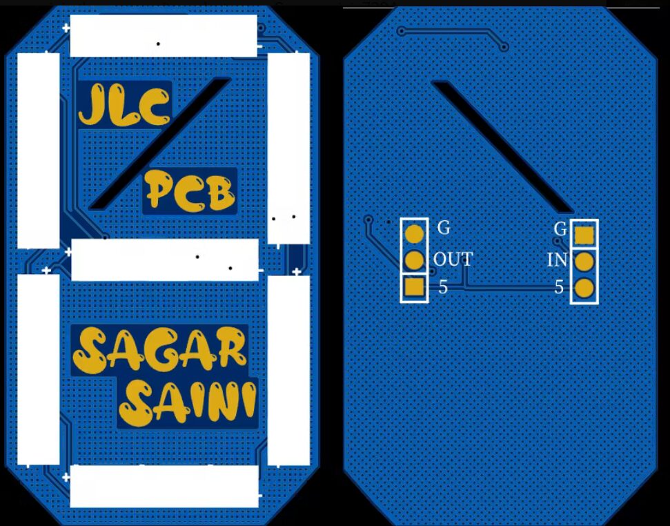

This is the main PCB design for displaying numbers and other letters.
All files related to this project can be downloaded at the end of the article.
Step 13: Troubleshooting
-
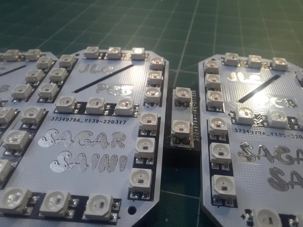
“Din” and “Dout” are connected in series; if connected in reverse or disconnected, the entire device will stop working.
-
As shown in the above figure, connect the “Dash” part.
-
Make sure all connections are soldered well; dry soldering can lead to changes in data values and colors.
-
When soldering, be careful not to let the PCB temperature get too high.
Original link:https://www.instructables.com/ESP8266-Wi-Fi-Based-7-Segment-Display-Clock/
GitHub repository link: https://github.com/halfstudents/ESP8266-Wi-Fi-based-7-Segment-Display-clock
Project author:sainisagar7294
Hardware Arsenal
DF Hardware Arsenal
Click to learn more👆
If you have anything to say, feel free toleave a message!
All materials involved in the project can be downloaded in the following ways:
1. You can click the “Reference Materials” to download from the author’s repository on GitHub!
2. You can click the “Read the original text” to download from the community forum!
3. Students who have difficulty accessing GitHub can reply “0713 Clock Project” in the public account to download!
(Note: For past projects, if the link is broken, you can also search for the project name in our community forummc.dfrobot.com.cn for free download)
Past Project Review
▼ Make a small spider robot with Arduino

Click to read👆
▼ Make a remote-controlled hexapod robot

Click to read👆
▼ Make a small quadruped robot based on ESP32
Click to read👆
▼ Spot’s little follower is here, capable of running, jumping, and walking!
Click to read👆
▼ High expandability, Stanford Pupper’s little brother is here!
Click to read👆
▼ How to make a Strider camera robot using ESP32-CAM and 3D printed parts
Click to read👆