AuthorForum Account:Su ZifangxuanRecently, I have been learning about USB communication and thought about whether the Ai8051, which has USB and a 40MHz main frequency, could simulate the logic analyzer of the Cypress microcontroller that runs at 24MHz found online.I tried it, and it actually works. Although the performance is not as good, it can run.Here is a screenshot of it running, with the host computer using the open-source PulseView.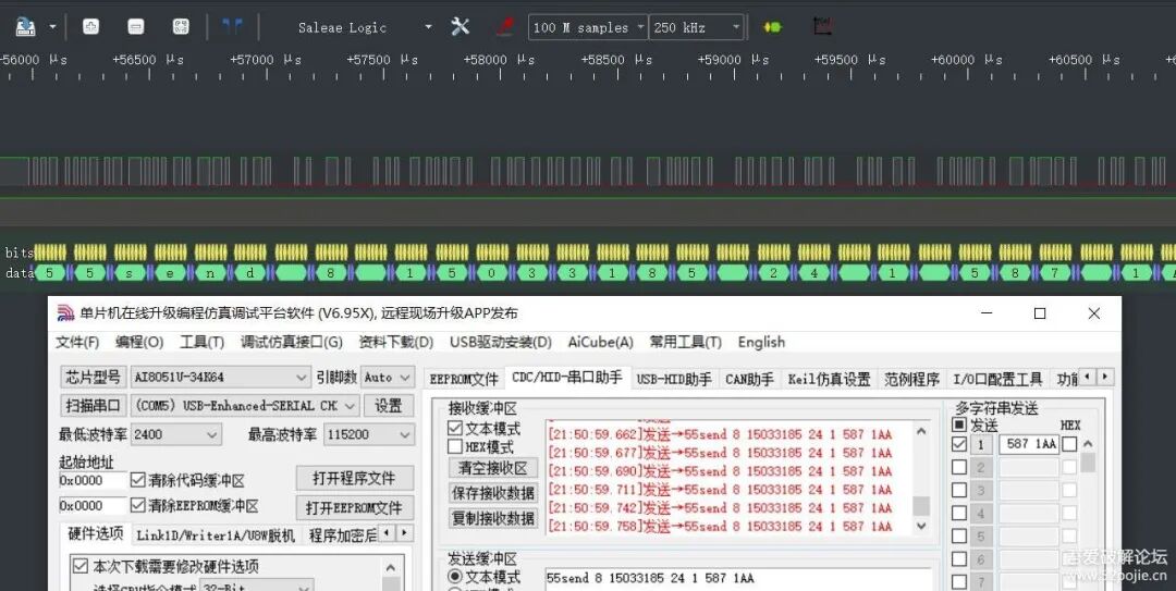 By capturing packets and examining the source code of the FX2LAFW firmware, it can be seen that sigrok uses libusb to communicate with the lower computer through the vendor descriptor.The device descriptor, configuration descriptor, and string can be copied directly from the source code. Since the finished logic analyzer is a high-speed device, the maximum packet size for the corresponding endpoint descriptor must be changed from 512 to 64.The setup-related configurations can be copied from the official USBCDC example.What needs to be added is the handling of the vendor descriptor.Relevant source code in the firmware
BOOL handle_vendorcommand(BYTE cmd)
{
        /* Protocol implementation */
        switch (cmd) {
        case CMD_START:
                /* Tell hardware we are ready to receive data. */
                vendor_command = cmd;
                EP0BCL = 0;
                SYNCDELAY();
                return TRUE;
        case CMD_GET_FW_VERSION:
                send_fw_version();
                return TRUE;
        case CMD_GET_REVID_VERSION:
                send_revid_version();
                return TRUE;
        }

        return FALSE;
}
Here, cmd is a structure
struct cmd_start_acquisition {
        uint8_t flags;
        uint8_t sample_delay_h;
        uint8_t sample_delay_l;
};
flags indicate whether it is for 30MHz or 48MHz, and sample_delay is main frequency/sample rate – 1. I fixed the main frequency at 40MHz and converted its sample rate to the timer count for 40MHz.
void cmd_start_over()
{
        // Restore sample rate
        u32 u32Samplerate;
        // Receive sample rate in Hz   Timer setting value
        u16 u16Delay;
        // Error handling not added

        u16Delay=cmdStartInfo.sample_delay_h;
                u16Delay<<=8;
                u16Delay+=cmdStartInfo.sample_delay_l;
                u16Delay++;
        //1<<6
        if(cmdStartInfo.flags==0x40)//48M reference
        {
                //delay = SR_MHZ(48) / samplerate - 1;
                u32Samplerate=48000000UL/u16Delay;

        }
        else//30M reference  0<<6
        {
                u32Samplerate=30000000UL/u16Delay;
        }

                // Initialize buffer
        Buffer_Init();
        // Start timer
        Timer0_Start(u32Samplerate);
}


// Start timer
void Timer0_Start(uint32_t xHz)                // Configurable frequency @40.000MHz
{
    uint32_t reload;


    AUXR |= 0x80;                        // Timer clock 1T mode
    TMOD &= 0xF0;                        // Set timer mode


    // Calculate reload value
    // System clock frequency is 40MHz, in 1T mode each clock cycle is 1/40MHz = 0.025us
    // Timer period = 1/xHz seconds = (1/xHz)*1000000 us
    // Required clock cycles = (timer period)/0.025 = (1000000/xHz)/0.025 = 40000000/xHz
    // Since the timer counts up 16 bits, reload value = 65536 - (40000000/xHz)
    reload = 65536UL - (40000000UL / xHz);


    TL0 = reload;                        // Set timer initial value low byte
    TH0 = reload >> 8;                // Set timer initial value high byte


    TF0 = 0;                                // Clear TF0 flag
    TR0 = 1;                                // Timer 0 starts counting
    ET0 = 1;                                // Enable timer 0 interrupt
}
Once the timer starts, sampling begins. The sampled data for 8 channels occupies 1 byte, with channel 0 as bit0 and channel 7 as bit7.The Ai8051 has a 32K xdata memory, and a large circular buffer should be allocated as much as possible, with one pointer for reading and one for writing. When reaching the end, it returns to the beginning, maximizing buffer utilization.
// Timer interrupt, fill in data
void Timer0_Isr(void) interrupt 1
{
        BYTE xdata *nextPtr = wPtr + 1;
    if (nextPtr >= bufferEnd) {  // Pointer wrap
        nextPtr = RxBuffer;
    }
    if (nextPtr == rPtr) {  // Buffer full
        //memOver=1;
                Timer0_Stop();
    }
    *wPtr = P1;
        u16Remain--;// Remaining space -1
        u16Available++;
    wPtr = nextPtr;// Pointer +1
}
In the main loop, you just need to keep sending this data.
// Check if USB is idle
                if(!UsbInBusy)
                {
                        // Used space reaches 64
                        if(u16Available>=64)
                        {
                                // Send data
                                EUSB =0;
                                UsbInBusy=1;
                                usb_write_reg(INDEX, 2);
                                for(i=0;i<64;i++)
                                {
                                        usb_write_reg(FIFO2, *rPtr);  // Send received data
                                        rPtr++;
                                        if (rPtr >= bufferEnd) {  // Pointer wrap
                                                rPtr = RxBuffer;
                                        }
                                }
                                u16Remain+=64;// Remaining space +64
                                u16Available-=64;
                                usb_write_reg(INCSR1, INIPRDY);
                                while (usb_read_reg(INCSR1) & INIPRDY);
                                usb_write_reg(INCSR1, INIPRDY);
                                EUSB = 1;
                        }
                }
The code is quite simple; it basically just modifies the official example a bit. However, the current version still has many issues.There may be packet loss or other situations; data sampled at 500K and 1M is completely unusable. Reducing to 250K makes it usable, and it is also affected by communication speed and algorithm inefficiencies. At 1M sampling rate, it can only sample for 30ms, at 500K it can sample for 120ms, and at 250K or below, it can collect data for a long time.That’s it for now; I hope this can inspire someone interested to optimize it.Finally, the usage is the same as that of the simple logic analyzers sold online, and the source code can be found in the attachment.25.7.13Adjusted the interrupt priority of Timer 0.Added a 100K PWM test waveform with a 50% duty cycle on P01.Fixed the bug where P35 had no clock output.Currently, 500K, although it can only last 112ms, is relatively stable and usable.Attachment download can be found in the lower left corner of the original forum post.Reference documents and videosAi8051 Product SpecificationHost communication source codehttps://github.com/sigrokproject … rc/hardware/fx2lafwLower computer firmware source codehttps://github.com/sigrokproject … fx2lafw/tree/masterUSB extension library and usage examples | This post consults USB, basically helps you complete USB program developmenthttps://www.stcaimcu.com/thread-16791-1-1.htmlSTC’s USB coursehttps://www.bilibili.com/video/BV1T8411r7uaQinheng’s USB coursehttps://www.bilibili.com/video/BV1sy4y1n7d9
– Official Forum
www.52pojie.cn
👆👆👆
Public AccountSet as “Starred”,so youwon’t missnew message notificationssuch asopen registration, excellent articles, and surrounding activitiesand other announcements