
Lesson 1: Traffic Lights
2018/10/15
Students, traffic lights are not unfamiliar to us; their existence makes our traffic life safer and more orderly. Do you know who invented the first traffic light? Let’s find out together. In 1868, British mechanical engineer J. P. Knight installed the world’s first gas-powered traffic light in front of the Palace of Westminster in London. It was from this time that traffic began to enter our lives. With the advancement of technology, traffic lights have also seen significant improvements; what once required manual control is now automatically controlled by programs. In this lesson, we will simulate the control method of traffic lights.
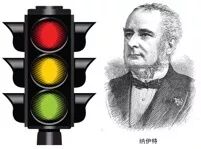
Figure 3-1: Traffic Light and Its Inventor
Traffic Lights
【Science and Knowledge】
The previous introduction mentioned that people started using traffic lights as early as 1868. With continuous technological advancements, traffic lights have been constantly changing; most traffic lights at intersections now use LED lights. LED should be familiar to students, as it is used in many places in our lives, such as electronic screens and indicator lights. As a new light source that is energy-efficient, high-brightness, and low-heat, it has been widely accepted. Do you know the origin of LEDs? Let’s find out together.
LED (Light Emitting Diode) is a solid-state semiconductor device made of compounds containing gallium, arsenic, phosphorus, and nitrogen that can convert electrical energy into visible light. It was invented in 1962 by the renowned inventor Nick Holonyak from the University of Illinois. LEDs can emit different colors of light mainly due to the use of different compound combinations, for example: gallium arsenide diodes emit red light, gallium phosphide diodes emit green light, silicon carbide diodes emit yellow light, and gallium nitride diodes emit blue light.
In the process of using LEDs, we need to note that they are electronic components composed of an anode (positive) and a cathode (negative). To control an LED, we generally connect the anode to the positive power supply and the cathode to a control port that can change the high and low levels. By changing the high and low levels of the control port, we can control the LED’s on and off. An LED requires two wires to connect the anode and cathode for control.
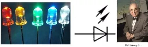
Figure 3-2: Light Emitting Diode, Circuit Symbol, and Its Inventor
We have learned about the control method of an LED, but in practical use, we often need to control dozens or even hundreds of LEDs together. Is there a simpler way to connect the circuit? Please look at the circuit diagram below, where you can find the answer.
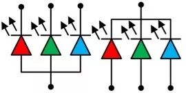
Figure 3-3: Common Anode and Common Cathode Connection of LEDs
As shown in Figure 3-3, the method is quite simple; we just need to connect all the anodes or cathodes of the LEDs together, and connect the other pins to the control ports separately, which can reduce the number of required wires by nearly half. This connection method has a professional name: when all the anodes of the LEDs are connected together, it is called a common anode connection, and when all the cathodes are connected together, it is called a common cathode connection.
Traffic Lights
【Technology and Practice】
01
Task Description
Use Arduino to control the LED lights on the traffic light module to turn on and off.
02
Preparation
One Arduino Uno R3 main control board, one IO expansion board, one traffic light module, one USB download cable, and one traffic light module connection cable. Below is a brief introduction to the usage of the traffic light module.
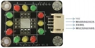
Figure 3-4: Traffic Light Module
As shown in Figure 3-4, the traffic light module consists of 12 LEDs, simulating the design of an intersection traffic light, divided into two horizontal groups and two vertical groups. During control, all signal lights are divided into three groups, referring to the characteristic that only one direction can pass at a time. The red lights of the two horizontal groups and the green lights of the two vertical groups are controlled to turn on and off simultaneously; similarly, the green lights of the two horizontal groups and the red lights of the two vertical groups are controlled to turn on and off simultaneously, and all yellow lights are controlled to turn on and off simultaneously. The traffic light module uses a common anode connection for all LEDs. According to the direction shown in the figure, the pins from top to bottom are VCC, horizontal green and vertical red control pins (referred to as green-red pins), yellow LED control pin (referred to as yellow pin), and horizontal red and vertical green control pins (referred to as red-green pins). During control, connect VCC to 5V, and connect the other pins to digital interfaces on the Arduino. When the green-red pin is low, the horizontal green and vertical red LEDs turn on simultaneously; when the yellow pin is low, all yellow LEDs turn on; when the red-green pin is low, the horizontal red and vertical green LEDs turn on.
03
Hands-on Practice
Figure 3-5: Traffic Light Wiring
As shown in Figure 3-5, connect the VCC pin of the traffic light module (blue wire) to any VCC pin on the IO expansion board, connect the green-red pin of the traffic light module (green wire) to pin D2, connect the yellow pin of the traffic light module (red wire) to pin D3, and connect the red-green pin of the traffic light module (black wire) to pin D4.
Finally, connect the voltage selection jumper cap on the IO expansion board to the 5V position, and then use a USB cable to connect the Arduino Uno to the computer.
In the previous introduction, we mentioned a term called “digital pins.” Digital pins, also known as digital IO pins, refer to pins that can only be set to high or low output, or can only detect high or low input signals. The Arduino Uno has a total of 14 digital pins, numbered D0 to D13, where digital pins D0 and D1 are used for communication between the computer and the Arduino. Digital pin D0 is for receiving signals, and digital pin D1 is for sending signals. Upon careful observation, we will find that these two pins are marked with “tx, Rx.” Therefore, it is recommended not to connect devices to digital pins D0 and D1 during wiring.
04
Program Design
Our task is to control the on and off of the three groups of LEDs on the traffic light module. We know that the anodes of the LEDs are already connected to VCC, and the cathodes of the three groups of LEDs are connected to pins D2, D3, and D4, so we only need to control the high and low levels of the corresponding pins through the program to achieve the control of the LED’s on and off.
In the first lesson, we learned that an Arduino program must contain a loop() function, also known as the main loop function, and all programs will be included in the main loop function. Therefore, in ArduBlock, there must also be a main program block. When writing graphical programs, our first step is to add a main program block. We can click on the “Control” item, and in the pop-up selection box, we can find the main program block, as shown in Figure 3-6. By holding down the left mouse button, we can drag the main program block into the program writing interface.

Figure 3-6: Main Program Block
The program blocks for controlling the high and low levels of pins in ArduBlock are shown in Figure 3-7, where the number at # represents the pin number, which can be filled in with the pin to be controlled. The red block labeled HIGH indicates the high and low levels of the pin; HIGH represents high level, and LOW represents low level. In this task, we choose HIGH, which means the LED cathode is at high level (positive), and the LED is off; if we choose LOW, the LED is on.
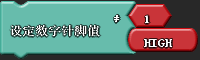
Figure 3-7: Digital Pin Level Control Program Block
We click on the “Pin” item, and in the pop-up selection box, we can find this program block, then hold down the left mouse button to drag it into the programming interface and place it on the main program block, and we find that the two program blocks will automatically combine together.

Figure 3-8: Delay Program Block
Click on the “Utility Commands” item, and in the pop-up selection box, we can find this program block, with the unit in milliseconds, and drag it into the programming interface at the appropriate position.
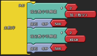
Figure 3-9: LED Blinking Program
Figure 3-9 is our first simplest ArduBlock program, which is very simple; it sets digital pin 2 to low level, turns on the LED, delays for 500 milliseconds, then sets the pin to high level, turns off the LED, and after a delay of 500 milliseconds, the first cycle ends, and the program starts executing from the main program again, continuously looping. After completing the program writing, we click “Download to Arduino”; first, the Arduino IDE will automatically convert the graphical interface into the corresponding Arduino program, and then the program will automatically download to the Arduino Uno R3 development board. We can observe the LED continuously blinking in a loop.
Here, students may have a question: why does low level control the LED to turn on, while high level turns it off? It seems contrary to our normal logic. In fact, this is related to the wiring method we mentioned earlier, as our traffic light module uses a common anode wiring method.

Figure 3-10: LED Blinking Arduino Program
As shown in Figure 3-10, this is the corresponding automatically generated Arduino program. We can see that it consists of two functions: loop() and setup(), which are also called the framework functions of Arduino. All ArduBlock graphical programs converted into Arduino programs will inevitably include these two functions. The setup() function is the initialization configuration function, completing the initialization work of the entire program. The Arduino pins can both send control signals to the outside (output) and detect external signals (input). Here, we need to use the pins to control the LED lights, so they need to be configured as output status, which is done using the pinMode function. In the parentheses of the function, the first parameter indicates the pin number, and the second parameter indicates the input/output status, with INPUT for input and OUTPUT for output. Note that both words must be in uppercase.
In the loop function, the digitalWrite function is used, which is used to configure the high and low levels of digital pins. The first parameter in the parentheses indicates the pin number, and the second parameter indicates the pin status, with HIGH indicating configured as high level and LOW indicating configured as low level. The delay() function is used to create a delay, with the delay time in milliseconds.
Traffic Lights
【Tasks and Implementation】
Have you ever observed the changing process of traffic lights? The general workflow of traffic lights is green light – yellow light flashing for 3 seconds – red light – green light. Since our traffic light module controls both horizontal and vertical red and green lights together, and all yellow lights are also controlled together, it cannot fully simulate the workflow of traffic lights. Therefore, we will set the workflow to start with the horizontal green light and vertical red light on, while the other lights are off. After 2 seconds, both red and green lights will turn off, and the yellow light will turn on, then the yellow light will flash three times at a frequency of 1 second, after which the yellow light will turn off, and the horizontal red light and vertical green light will turn on, while the other lights are off. The yellow light will turn on, and then the yellow light will flash three times at a frequency of 1 second, and so on in a loop.
01
Task Objective
Assemble the traffic light simulator and program it to operate as follows: start with the horizontal green light and vertical red light on, while the other lights are off. After 2 seconds, both red and green lights will turn off, and the yellow light will turn on, then the yellow light will flash three times at a frequency of 1 second, after which the yellow light will turn off, and the horizontal red light and vertical green light will turn on, while the other lights are off. The yellow light will turn on, and then the yellow light will flash three times at a frequency of 1 second, and so on in a loop.
02
Preparation
One Arduino Uno R3 main control board, one IO expansion board, one traffic light module, one USB download cable, one traffic light module connection cable, one set of traffic light simulator installation board, three M3X6 copper pillars, eleven M3X6 pan head screws, three M3 nuts, four M3X50 copper pillars, one lithium battery, one power cable, and one piece of Velcro.
03
Model Assembly
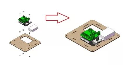
Figure 3-11: Traffic Light Simulator Installation Step 1
1. First, take out board 2 from the traffic light installation board, as shown in Figure 3-11. Combine the IO expansion board and Arduino Uno R3 together, then use M3X8 pan head screws, M3 nuts, and M3X6 copper pillars to install them at the indicated positions. Then use Velcro to attach the battery to the rectangular box shown in the figure, and connect the power cable to the power interface of the Arduino Uno R3.
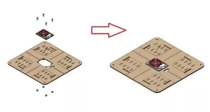
Figure 3-12: Traffic Light Simulator Installation Step 2
2. Take out board 1, and as shown in Figure 3-12, use M3X8 pan head screws and M3 nuts to install the traffic light module at the designated position on board 1. Then connect the traffic light module connection cable to the traffic light module and insert it through the oval hole shown in the figure.
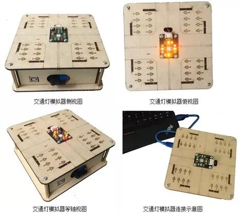
Figure 3-13: Traffic Light Simulator Installation Step 3
Finally, take one piece each of boards 3 and 4, two pieces of board 5, four M3X50 copper pillars, and four M3X6 pan head screws, and four M3 nuts. First, insert boards 3, 4, and 5 into the corresponding slots on board 2, then connect the traffic light module to the IO expansion board according to the wiring method shown in Figure 3-5, and complete the remaining assembly.
04
Program Design
Students, have you noticed that in the task description, we mentioned that the yellow light should flash three times? This actually means we want the yellow light to blink three times in a loop. In the program design, we can write the yellow light on and off program three times. Here, we will introduce a method to make the program more concise and efficient – the for loop. This is also a very commonly used loop structure in program design.
The for loop in Arduino programming language is a function. The function can be understood as a subroutine that performs a specified operation. The function used to loop through a certain function is the for function, and its general form is:
for (i=M; i<N; i=i+1)
{
}
The first part before the first semicolon, i=M, is called the initialization expression, which sets i to M before the loop starts; the second part between the two semicolons, i<N, is called the condition expression, which is a judgment statement that executes the statements in the braces only when i is less than N; the third part after the second semicolon, i=i+1, is called the end loop body, which indicates that after executing the statements in the braces, i will be incremented by 1, and then the i<N judgment will be repeated.
In ArduBlock, the program module for implementing loop execution is shown in Figure 3-14. The number 5 in the red box indicates the number of loop executions, which can be changed to any positive integer. The blank box is for the program to be executed.

Figure 3-14: Loop Program Module
The reference program for simulating traffic lights is shown in Figure 3-15.
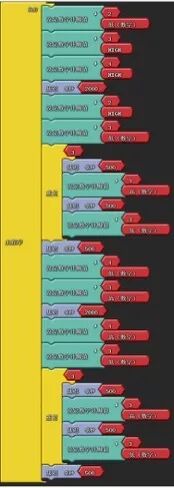
Figure 3-15: Traffic Light Simulation Program
After downloading the program to the Arduino development board, we can observe that the traffic light module completes the predetermined display sequence.
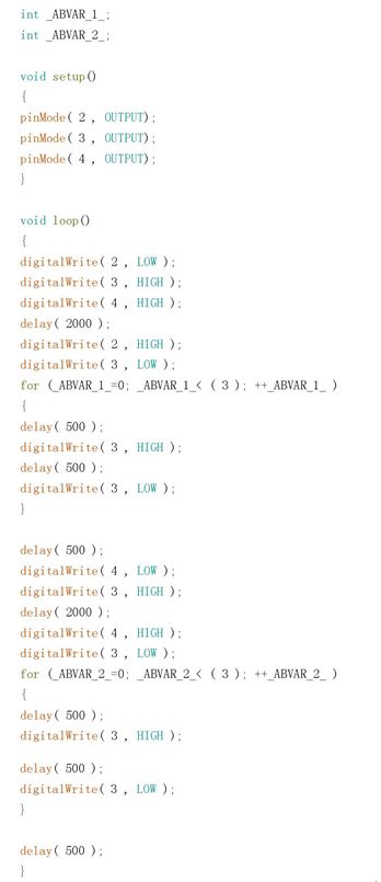
Figure 3-16: Traffic Light Loop Arduino Program
As shown in Figure 3-16, this is the corresponding generated Arduino IDE program. We will provide a brief introduction to the code:
1) First, the loop program module in ArduBlock corresponds to the generated Arduino program, which is the for loop function, and to identify the number of loops, the program automatically generates two variables: _ABVAR_1_ and _ABVAR_2_;
2) A variable is a quantity that can change, used in the program to store values, characters, etc. We usually give variables easy-to-remember names, called variable names. For example, _ABVAR_1_ is a variable name automatically generated by ArduBlock according to its naming rules. If you have learned about LEGO NXT robots, there is a module in the programming software called “container,” which is essentially a variable. We can think of the stored value as water; assigning a value to a variable is like pouring water into a cup, and when we use the variable value, it is like pouring water out of the cup.
3) When using variables, we need to pay attention to certain variable naming rules: they must start with a letter or underscore, followed by letters, numbers, or underscores. For example, _b1 and b_1 are correct, while 3a is incorrect.
Figure 3-17: Traffic Light Simulator Results Display
Traffic Lights
【Expansion and Reading】
Why were red, yellow, and green chosen as the three colors for traffic lights? This starts with red. Among all colors, red is the most attention-grabbing. Perhaps because red is the color of blood, it has always been associated with “warning” and “prohibition” in various cultures. Therefore, it is only natural that the signal light representing prohibition uses red. But why is green used to represent permission? This is because, at that time, people generally believed that red and green, like black and white, are complementary colors. From the color wheel, it can be seen that red and green are symmetrically positioned, differing by about 180 degrees, so red and green are a pair of colors that are not easily confused. Since red represents prohibition, it is logical to use the opposite green to indicate permission. Yellow is positioned exactly between red and green on the color wheel, with a significant color difference from both bright colors, making it suitable to serve as the intermediate signal indicating that the red and green lights are about to change.
Let me share a little secret: most countries’ traffic lights do not actually use pure red and pure green, but rather slightly yellowish red and slightly bluish green. This is mainly to help those with red-green color blindness to distinguish the colors of the signal lights more easily.
(Article Author: Gao Kai, Beijing No. 2 Middle School)


Long press the QR code to follow