❝
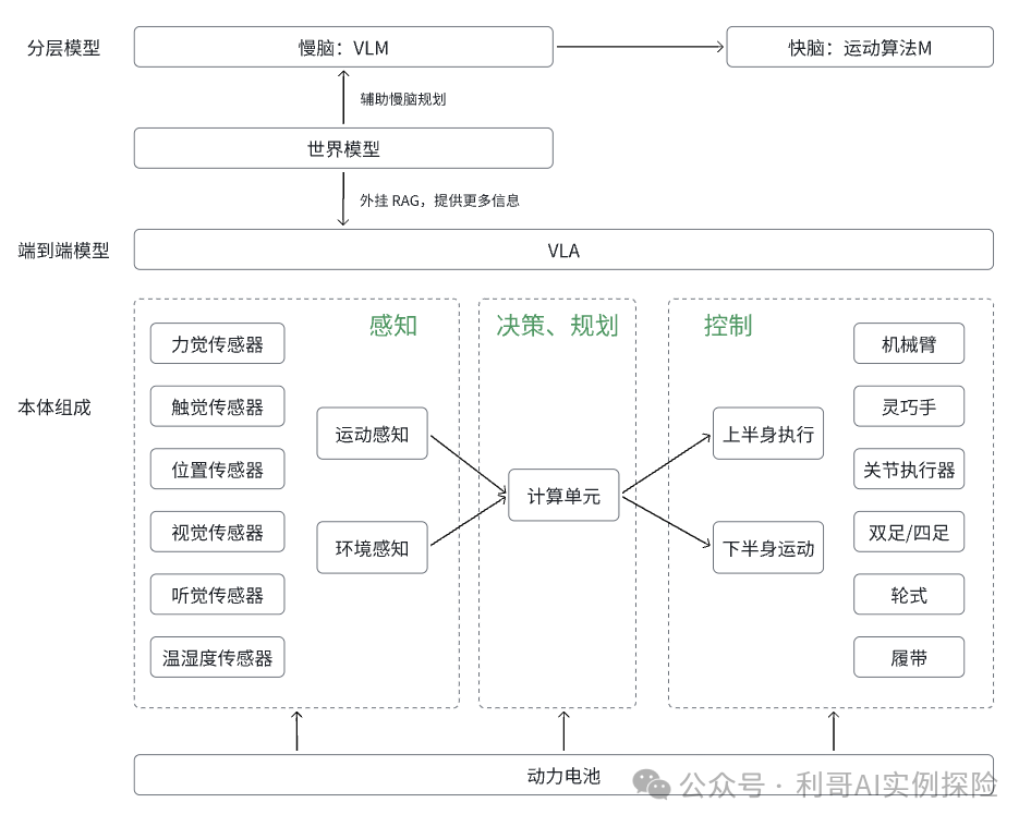
This article focuses on the three core hardware components of embodied intelligence, which are considered the “high ground of technological value” in the entire embodied intelligence hardware industry chain—perception architecture, computing power architecture, and execution architecture. These three are not isolated but correspond precisely to the entire process of interaction between embodied intelligence and the physical world, collectively forming its “perception – decision – action” closed-loop capability.
Perception Architecture: The “Sensory Ensemble” of Embodied Intelligence
As the “first bridge” to establish a connection with the physical world, it acts like the robot’s “eyes, ears, and skin,” responsible for accurately capturing information such as light, distance, force, and temperature from a complex and variable environment, transforming these “physical signals” into “digital data” that computers can understand, providing the most basic “raw materials” for subsequent decision-making.
Computing Power Architecture: The “Brain and Nervous Center” of Embodied Intelligence
If perception is the “information entry point” and execution is the “action output,” then the computing power architecture is the “core hub” connecting the two. It must play the role of the “brain,” processing massive amounts of perceptual data, running AI large models, completing complex scene understanding and long-term task planning; it also has to take on the responsibilities of the “cerebellum,” providing high-frequency, low-latency responses to control limb movements in real-time, ensuring seamless integration of decision-making and action.
Execution Architecture: The “Skeleton and Muscles” of Embodied IntelligenceRegardless of how precise the perception is or how powerful the computing capability, execution architecture is ultimately required to “land”—it is responsible for converting the “digital commands” issued by the brain into precise and forceful physical actions in the real world. From delicately picking up a grape to a bipedal robot walking steadily up stairs, the performance of the execution architecture directly determines the “value realization capability” of embodied intelligence. This article will start from the hardware level, dissecting these three architectures layer by layer: from sensor selection at the perception end, to chip layout and collaborative logic at the computing power end, and finally to drive solutions and transmission design at the execution end, showing you how embodied intelligence gradually acquires the ability to “perceive the world, think about problems, and change the physical environment” through hardware combinations.
1. Perception Architecture: The “Sensory Options” of Robots—Is it “Staring” or “Seeing Through”?
Humans perceive the world through their five senses, and robots also have their own “sensory ensemble,” with a core task: to translate the “tangible and visible” information of the physical world, such as light, distance, and temperature, into “digital codes” that computers can understand. The current mainstream “sensory combination” centers around “eyes” (visual sensing), supplemented by “balance” (positional sensing), occasionally adding “touch” and “force” as “additional skills,” striving to avoid being “blind and clumsy” robots.
1.1 Visual Sensing: The “Eye Selection Guide” for Robots
❝
For robots, seeing the world essentially means selecting an “eye package”—whether to rely solely on cameras for “naked-eye observation” or to add LiDAR for “seeing through”? The technical roots of this issue are actually borrowed from autonomous driving—after all, both need to “see the road in real-time and avoid collisions,” and even the debate over “pure vision vs. multi-sensor fusion” has been directly imported.
Pure Vision: The King of Cost-Effectiveness, Using Cameras to “Stare Out 3D Effects”
Just as we use our two eyes to judge distance, robots rely on multiple cameras and algorithms to “imagine” a 3D world from 2D images. The advantage is that it is “cheap and abundant,” capable of continuous upgrades leveraging computer vision, suitable for businesses looking to “mass produce”; the downside is that it struggles with backlighting and heavy rain, easily becoming “blind” in adverse weather.
LiDAR / Millimeter-Wave Radar: The “Seeing Through” Package, Specializing in Visual Blind SpotsLiDAR is an “active light detection” technology that can accurately measure distance and shape regardless of lighting conditions, equivalent to equipping robots with “night vision goggles + range finders”; millimeter-wave radar is even more powerful, capable of “penetrating obstacles” to measure speed and distance in rainy or foggy conditions, though it sacrifices some accuracy. Among them, “structured light / ToF” is a “close-range expert”—used for indoor handovers and obstacle scanning, for instance, if a robot wants to “gently pick up a grape,” it must rely on ToF to accurately measure the distance from its fingertip to the grape, avoiding “squeezing too hard or missing it altogether.”
Multi-Sensor Fusion: The “Luxury Safety Package,” Expensive but StableIn simple terms, it means “not putting all eggs in one basket.” Common combinations include “vision + LiDAR” (where the camera supplements “semantics,” such as recognizing “this is a cat, not a dog”; LiDAR supplements “accuracy,” such as calculating how far the cat is from itself), suitable for scenarios like autonomous driving and outdoor robots where “a collision could be catastrophic”; “vision + millimeter-wave radar” is a “cost-effective upgrade,” usable in rain without being expensive; the top configuration of “vision + LiDAR + millimeter-wave radar” is like giving the robot “triple insurance,” maximizing reliability, but the cost can be painful for manufacturers.
Summary:Choosing visual sensing is not about “who has better technology,” but about “considering the budget and needs”—if you want to save money, choose pure vision; if you need accuracy, add LiDAR; if you want to avoid accidents, go for multi-sensor fusion, because getting the robot’s “eyes” right can help avoid “unnecessary detours.”
1.2 Positional Sensing: The Robot’s “Balance Master”—Avoiding Getting “Dizzy” After Two Steps
❝
If visual sensing solves “what’s around me,” positional sensing addresses “where am I, and where do I want to go”—equivalent to the robot’s “navigation + balance system,” primarily relying on the “IMU (Inertial Measurement Unit)” and “odometer” as a pair of “partners,” since relying on a single sensor can easily lead the robot to “go off course or fall over.”
IMU: The Robot’s “Inner Ear,” Balance Relies on It
This device is known as the robot’s “balance expert,” containing a three-axis accelerometer (measuring “how fast or where to go”), a three-axis gyroscope (measuring “how many degrees it has turned and whether it will tilt”), and a three-axis magnetometer (calibrating direction using the Earth’s magnetic field to avoid gyroscope “drift”). For example, when a robot walks up stairs, the IMU can sense in real-time whether its “body is tilted,” preventing it from “missing a step and falling down”; however, it has a small flaw—it can “accumulate small errors,” leading to larger deviations over time, and it is sensitive to temperature changes and self-vibrations that can “interfere with judgment.”
Odometer: The Robot’s “Step Counter,” Estimating DistanceEssentially, it measures how far the moving parts have traveled to infer position, divided into three types:
- Wheeled Odometer:Equipping wheels with “encoders” to calculate how many rotations and how far it has traveled, it is cheap but prone to “overturning”—if the wheels slip or the ground is uneven, the data becomes inaccurate, and the robot may “think it has traveled 10 meters when it has only gone 5 meters”;
- Visual Odometer:Using cameras to “track pixels,” observing how points in consecutive images have moved to infer how far it has traveled, available in monocular, binocular, and RGB-D versions;
- Laser Odometer:Using LiDAR to “match point clouds” between two frames to calculate displacement, it is more reliable than visual odometers in complex environments.
Practical Operation: No one relies solely on one type of odometer; they all team up with the IMU, using algorithms like Kalman filtering to “complement each other’s strengths”—for example, if the IMU is prone to drift, the odometer can calibrate in real-time; if the odometer is prone to slipping, the IMU can supplement posture, ultimately allowing the robot to “walk straight and not get lost.”
1.3 Other Sensors: The Robot’s “Touch / Hearing Add-ons”—From “Seeing” to “Touching”
❝
Visual and positional sensing are the “basic models,” but for robots to interact “intimately” with the world, they need to add “touch, force, and hearing” as these “advanced skills”—after all, they can’t just “not know the weight of a cup when touching it or fail to distinguish directions when hearing a command.”
Touch Sensors: The Robot’s “Skin,” Judging Objects by Touch
Mainly installed on dexterous hands, fingertips, or body surfaces, responsible for “detecting the softness, texture, and shape of objects”—for example, when grasping an egg, it needs to be “gentle,” while grasping a stone requires “stability,” all relying on its signals. The current mainstream is “flexible sensors,” with the ultimate goal being “electronic skin” (a flexible sensing network covering the entire body), among which “piezoresistive” is the most mature (as pressure changes, resistance changes, allowing force measurement). However, it has very “double standards”: fingertips need to be “high precision” (even squeezing a screw must be accurate), while the body surface can be “low precision” (as long as it doesn’t hit a wall); the challenge lies in “materials and manufacturing”—it must be soft, capable of measuring multi-dimensional forces, and withstand deformation.
Force / Torque Sensors: The Robot’s “Force Meter,” Precisely Controlling Force to Avoid Overexertion
Unlike touch sensors that “feel surfaces,” these measure “point forces and torques”—for example, when a robot lifts something, it needs to know “how much effort it is using,” relying on these sensors. The mainstream is “six-dimensional force / torque sensors” (measuring 3 linear forces + 3 axial torques, installed on wrists and ankles), along with “joint torque sensors” (installed on joints to control torque). The advantages are “durable”—high rigidity, resistant to impact, and minimal zero drift, suitable for actions like walking and jumping; the downside is “expensive”—six-dimensional force sensors range from thousands to tens of thousands, and joint torque sensors also cost thousands, with manufacturers hoping for price reductions soon.
Hearing Sensors: The Robot’s “Ears,” Capable of Hearing Commands and Distinguishing Sounds
Composed of “multi-microphone arrays + sound processing chips + noise reduction algorithms,” they can “hear commands, determine directions, and recognize sounds”—for example, if you shout “robot, come here,” it can locate where you are; if it hears a fire alarm or glass breaking, it can also provide warnings. It is equivalent to equipping the robot with an “intelligent hearing aid” to avoid being “hard of hearing.”
Smell / Chemical Sensors: The Robot’s “Nose,” Only “Working” in Specific Scenarios
General-purpose robots rarely use these; they mainly work in “vertical fields”—for example, industrial applications for detecting hazardous gas leaks (on electronic noses), agriculture for checking if fruits are ripe (using infrared spectrometers), and security for detecting explosives. The drawbacks are obvious: “not universal” (sensors for gases cannot measure fruits), “customizable,” and “expensive,” making them not yet a “standard configuration.”
Temperature Sensors: The Robot’s “Thermometer,” Preventing Overheating and Measuring Environment
Divided into “internal monitoring” and “external monitoring”: internal measures the temperature of motors, batteries, and computing units (to prevent overheating), while external measures environmental temperature and the temperature of contact objects (for example, when touching a hot water cup, it needs to know it is “hot”), achieved through thermocouples and thermistors—equivalent to equipping the robot with a “temperature monitoring device” to avoid “fever” or “touching hot objects.”
2. Computing Power Architecture: The Robot’s “Brain Office”—Is it “Remote Work” or “On-the-Go Work”?
If perception is the “information entry point” and execution is the “action output,” then the computing power architecture is the robot’s “brain + nervous center”—it must process massive amounts of perceptual data, run AI large models (the brain’s “deep thinking”), and control limbs with high-frequency, low-latency movements (the cerebellum’s “real-time response”), equivalent to being both a strategist and an athlete, which is no small feat.
The core contradiction is “demand fragmentation”: the brain requires “high computing power” (to process multi-modal data and run VLM large models), while the cerebellum needs “fast response” (sending commands to joints hundreds of times per second, with delays not exceeding milliseconds). Moreover, it must be “energy-efficient and reliable”—after all, robots are mobile and cannot carry a “large power supply,” nor can they “make a mistake and crash into a wall.”
Currently, the industry lacks a “perfect solution” and is divided into three factions: “cloud computing faction” (remote work), “edge computing faction” (on-the-go work), and “hybrid faction” (balancing both sides).
2.1 Cloud Computing Solutions: The Robot’s “Remote Headquarters”—Complex Tasks Handed to the Cloud, Acting Only as “Executors”
❝
The idea is simple: the robot body is only responsible for “perception (capturing video, collecting data) and execution (moving arms and legs),” while complex “thinking” is entirely handed over to cloud servers—equivalent to the robot “consulting the cloud when in doubt.”
Main tasks include:Model Training: The “Birthplace” of AI Large Models
Embodied intelligence relies on VLM large models (visual language models), which have a massive number of parameters and can only be “trained” in cloud data centers—after all, it requires hundreds or thousands of GPUs to compute together, which the robot body “cannot accommodate or carry.”
Complex Task Planning: Long-Term Thinking Relies on the “Headquarters”
For example, if you want the robot to “clean the room” (first pick up clothes, then wipe the table, and finally take out the trash), with many steps and a need to plan the order, the robot uploads the task to the cloud, which calculates the steps and sends them back for the robot to follow.
Large-Scale Data Analysis: Collective Upgrades via “Cloud Review”
When many robots work simultaneously, the massive data collected (such as where collisions are likely to occur or which actions are not smooth) is uploaded to the cloud, where engineers analyze and optimize algorithms, then collectively upgrade all robots via OTA—equivalent to “one robot encountering a pitfall, benefiting all robots.”
API Calls to Large Models: Consulting Experts When Encountering Difficulties
For tasks the robot cannot handle (such as recognizing rare objects), it can call cloud-based general large models via API, “borrowing the expertise of specialists” to solve the problem.
The advantages are clear: “unlimited computing power” (cloud can expand as needed), flexibility (used as needed), and low barriers (the robot body does not need to be equipped with powerful chips); but the drawbacks are also painful:
- High Latency: Data has to “travel back and forth” between the robot and the cloud, making it impossible to achieve millisecond-level response for motion control (such as obstacle avoidance), and the robot may “collide before receiving the command”;
- High Bandwidth Pressure: Continuously uploading high-resolution video captured by cameras can “clog the network”;
- Dependence on Network + Privacy Risks: Without the internet, it becomes “dumb,” and uploading data may lead to leaks (such as videos from home scenarios).
2.2 Edge Computing Solutions: The Robot’s “Portable Computer”—Doing All Tasks Independently Without Relying on the Cloud
In contrast to the cloud faction: the robot body is equipped with “powerful chips,” completing perception, decision-making, and control locally—equivalent to “having a built-in computer for on-the-go work,” with the core advantage being “no latency and no dependence on the network,” allowing motion control to achieve “millisecond-level response.” However, the challenges are also significant: the robot has limited space and power consumption, needing to install both a “brain (high-performance AI chip)” and a “cerebellum (low-latency MCU),” while coordinating well, leading to two factions in the industry: “separated computing and control” and “integrated computing and control.”
(1) Separated Computing and Control: The Brain and Cerebellum “Work Separately,” Communicating via “External Buses”
This is currently the “most mature and commonly used” solution—installing the “brain (AI chip)” and “cerebellum (MCU)” on different chips, using external buses (such as CAN bus) to “transfer data,” equivalent to “two departments working separately, communicating via WeChat to send files.”
-
Brain (AI Chip): Responsible for “Complex Thinking”: Selecting top AI computing platforms available on the market, such as NVIDIA Jetson and Qualcomm robotics platforms, primarily running VLM large models and processing visual/language data, with a work frequency not high (7-9Hz, equivalent to thinking 7-9 times per second).
-
Cerebellum (MCU): Responsible for “Fast Execution”: It does not require high computing power but must be “fast”—using one or more high-performance MCUs to send control commands to joints over 200 times per second, such as “bending fingers 10 degrees” or “extending knees 5 degrees,” ensuring actions are “smooth and without stuttering,” with delays needing to be extremely low (otherwise the robot will “tremble”).
Advantages: Flexible and mature—if you want to upgrade the brain, just replace the AI chip; if you want to optimize the cerebellum, just replace the MCU, and the ecosystem is also well-developed;
Disadvantages: Relying on external buses to transfer data inevitably introduces “latency” and occupies space (the two chips need to be installed separately).
(2) Integrated Computing and Control: The Brain and Cerebellum “Share an Office,” Allowing for “Face-to-Face Communication” Without Latency
This is the “future direction”—integrating the brain and cerebellum into a single SoC chip, allowing for “real-time communication” via shared memory, equivalent to “two departments sharing an office, able to talk to each other immediately,” solving the “latency, space, and power consumption” issues of the separated solution. Currently, there are two representative solutions:
-
DiGua Robot RDK S100: A chip that integrates “CPU cores (6 cores A78AE, managing logic), BPU cores (Nash architecture, managing AI), and MCU cores (4 cores R52+, managing motion control),” truly achieving “single-chip closed-loop”—the brain thinks, and the cerebellum executes immediately without needing to “transfer files,” minimizing latency.
-
Intel’s Brain-Cerebellum Fusion Solution: Using the heterogeneous architecture of Core Ultra processors, tasks are “allocated” via software: motion control is handled by the CPU, environmental perception and VLM by the GPU, and voice recognition by the low-power NPU, all coordinated via shared memory—equivalent to “dividing areas for each department in a large office, eliminating the need to run far for communication.”
Advantages: Low latency, small size, low power consumption, and potential for cost reduction;
Disadvantages: The technical threshold is “extremely high”—the chip must simultaneously accommodate high AI computing power and strong real-time motion, making materials, heat dissipation, and software toolchains challenging, with the ecosystem still in its “early stages.”
❝
Summary: Currently, choosing “separated computing and control” is the “safe bet”—mature and flexible, suitable for scenarios with high performance requirements; choosing “integrated computing and control” is the “future bet”—with great potential, but waiting for technology and ecosystem maturity, suitable for manufacturers looking for “extreme integration and cost reduction.”
3. Execution Architecture: The Robot’s “Hands and Feet”—Can it “Move Things” or “Pinch a Needle”?
❝
The execution architecture is the robot’s “skeleton + muscles,” determining how “strong, fast, and precise” it can be—after all, even if the brain understands “to pick up a cup,” if the hands and feet lack strength or flexibility, it can only “stare blankly.”Currently, the industry’s competitive focus is on the “upper body”—especially the operational capabilities of arms and hands, as “being able to walk” is just the foundation, while “being able to work” is the core (such as industrial assembly and household chores). A complete execution architecture is divided into three main components based on the “power transmission sequence”: the drive system (providing power), the transmission system (transmitting power), and the end effector (performing tasks directly).
3.1 Drive System: The Robot’s “Power Source”—Is it “Slim Motors” or “Muscle Motors”?
❝
The core task is to “convert electrical energy into mechanical motion,” equivalent to the robot’s “engine,” consisting of “motors + drivers + encoders.” Currently, the mainstream is “electric drive” (precise control, clean, easy to integrate), but the requirements for motors in different parts vary greatly, leading to the emergence of several “specialized motors.”
- Frame-less Torque Motors: The “Slim Champion” of Humanoid Robot Joints
Traditional motors have shells and bearings that are “burdensome”; this type removes everything, leaving only the rotor and stator—equivalent to “successful weight loss,” allowing it to fit snugly into robot joints while enabling wiring and cooling pipes to pass through the center, particularly suitable for large joints like shoulders, elbows, and knees that require both flexibility and concealment of wires. Currently, humanoid robots primarily rely on it to “support joint functions.”
- Hollow Cup Motors: The “Small Motors” of Dexterous Hands
With no iron core in the rotor, they are ultra-lightweight and have extremely low inertia—equivalent to the “sprint champion on fingertips,” capable of responding in milliseconds with high control precision. The fingers of dexterous hands rely on them to grasp objects and perform delicate actions; after all, fingers have limited space and cannot accommodate “large motors,” making hollow cup motors just the right size and strength.
- Stepper Motors & Servo Motors: “Niche Specialized Models”
Stepper motors can “precisely control angles,” but their dynamic performance is poor, suitable for tasks like “turning eyeballs” (not needing speed, just accuracy) in low-cost scenarios; servo motors are an “integrated package”—combining motors, reducers, controllers, and position feedback, equivalent to “buying a ready-made product for direct use,” suitable for scenarios requiring “precise positioning and speed control.”
Of course, in addition to electric drives, there are also “non-mainstream options”:
- Hydraulic Drive: “Powerful but Bulky”—early Boston Dynamics’ Atlas relied on it for running and jumping, but the system is complex, prone to leaks, and power-hungry, leading to its near “elimination” in humanoid robots;
- Pneumatic Drive: “Fast and Cheap but Not Precise”—suitable for rapid gripping and switching in industrial settings (such as clamping parts on assembly lines), but lacks the precision for delicate tasks;
- New Material Drives: The academic community is experimenting with “shape memory alloys and dielectric elastomers,” suitable for future “soft robots” (like octopus-like soft robots), currently still in the laboratory stage.
3.2 Transmission System: The Robot’s “Power Converter”—Transforming “High-Speed Low Force” into “Low-Speed High Force”
❝
The motor outputs “high-speed, low torque” (for example, the motor spins quickly but has low force), but robot joints require “low-speed, high torque” (for example, the arm needs to move slowly but can lift heavy objects)—the transmission system serves as the “intermediate converter,” with the core being the “reducer,” equivalent to the robot’s “power transmission box.”
Currently, the mainstream reducers are divided into three types, each with its own “temperament”:

In simple terms: harmonic reducers are “delicate models,” suitable for humanoid robots to “show flexibility”; RV reducers are “muscle models,” favored by industrial robots but considered “too bulky” for humanoid robots; planetary reducers are “cost-effective models,” suitable for areas that do not require high precision.
There are also “innovative approaches,” such as Tencent Robotics X Laboratory’s “rope transmission”—concentrating heavy components like motors and reducers in the robot’s torso (proximal end) and using high-strength lightweight ropes to transmit power “remotely to the end of the arm,” equivalent to “shifting the weight back,” making the arm lighter, faster, and more energy-efficient, opening new avenues for high-dynamic operations.
3.3 End Effectors: The Robot’s “Hands”—Are They “Practical Grippers” or “Dexterous Hands”?
❝
The end effector is the robot’s “hand,” and its capabilities directly determine what tasks the robot can perform—whether it can only move things or can also pinch a needle depends entirely on it. Currently, the industry is divided into two factions: “gripper faction” (pragmatism) and “dexterous hand faction” (idealism).
(1) Gripper Systems: The “Workhorse” of the Industrial World—Simple and Reliable, Specializing in Repetitive Tasks
The core is the “two-finger or three-finger gripper,” a long-tested employee in industrial automation, designed with the philosophy of “being able to work is enough, no frills.”
- Advantages: Simple structure (few motors/actuators), mature control algorithms, high robustness (not easily broken), and low cost;
- Suitable Scenarios: Repetitive, structured tasks, such as grabbing standardized materials on assembly lines (grabbing boxes, grabbing parts), performing basic tasks of “picking and placing”;
- Hidden Skills: Don’t underestimate its simplicity; with a top-notch vision system and control strategy, it can also perform delicate tasks—such as aligning visually to use the gripper to “screw in screws” or “labeling.”
(2) Dexterous Hand Systems: The Robot’s “Ideal Hand”—Mimicking Humans, Pursuing General Flexibility
Unlike grippers that “perform specific tasks,” dexterous hands aim to be “as versatile as human hands”—able to grasp balls, hold pens, and twist bottle caps, which is key to embodied intelligence’s “path to general AI,” but the technical complexity is “maxed out.”
-
Basic Configuration: 3-5 fingers, 12-21 or even more degrees of freedom (human hands have 27 degrees of freedom), with driving methods including micro motors, hydraulics, and pneumatics, and transmission relying on micro linkages, gears, and ropes;
-
Technical Challenges: The “space, sensing, and control” trifecta
- Space Challenge: The fingertips are so small that they need to accommodate micro actuators while balancing power and size, equivalent to “installing a motor in a fingernail”;
- Sensing Challenge: Integrating force, touch, and visual multi-modal information, such as knowing “softness” when touching a sponge and “hardness” when touching metal;
- Control Challenge: Coordinating 21 degrees of freedom, such as needing “five fingers to cooperate in force” to grip a cup without crushing it or dropping it, leading to extremely high algorithmic complexity;
Current Status: Currently still in the “development phase,” far from large-scale commercial use, but once breakthroughs are made, robots will be able to perform more delicate tasks (such as cooking and caregiving at home).
❝
The evolution of hardware for embodied intelligence has always revolved around the collaboration and breakthroughs of the three major architectures: perception, computing power, and execution. From the route disputes of visual sensing to the trade-offs in computing power deployment, and the precision iterations of execution components, each technical path choice is a balance between demand and cost, present and future. In the future, as sensors become smaller, computing power chips become more integrated, and execution mechanisms become more dexterous, embodied intelligence will ultimately integrate more smoothly into the physical world, realizing its core value of “universal interaction.”