Basic Logic Instructions for Mitsubishi FX Series PLCs Input and Output Instructions (LD/LDI/LDP/LDF/OUT)
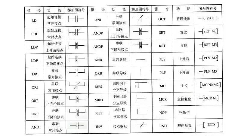
(1) LD (Input Instruction) is a command connected to a normally open contact with the left bus. Each logical line starting with a normally open contact uses this instruction.
(2) LDI (Inversion Instruction) is a command connected to a normally closed contact. Each logical line starting with a normally closed contact uses this instruction.
(3) LDP (Rising Edge Instruction) is a rising edge detection instruction for normally open contacts connected to the left bus, which only activates for one scan cycle on the rising edge of the specified element (from OFF to ON).
(4) LDF (Falling Edge Instruction) is a falling edge detection instruction for normally closed contacts connected to the left bus.
(5) OUT (Output Instruction) is a command that drives a coil, also known as an output instruction.
Usage Instructions for Input and Output Instructions:
1) LD and LDI instructions can be used for input contacts connected to the left bus and can also be combined with ANB and ORB instructions to achieve block logic operations;
2) LDP and LDF instructions maintain activation for one scan cycle only when the corresponding element is valid.
3) The target elements for LD, LDI, LDP, and LDF instructions are X, Y, M, T, C, S;
4) The OUT instruction can be used multiple times (equivalent to parallel coils), and for timers and counters, a constant K or data register should be set after the OUT instruction.
5) The target elements for the OUT instruction are Y, M, T, C, and S, but it cannot be used for X. Series contact instructions (AND/ANI/ANDP/ANDF)
● AND (AND Instruction) is a normally open contact series connection instruction that completes a logical “AND” operation.
● ANI (AND NOT Instruction) is a normally closed contact series connection instruction that completes a logical “NAND” operation.
● ANDP is a rising edge detection series connection instruction.
● ANDF is a falling edge detection series connection instruction.
Usage Instructions for Series Contact Instructions:
1) AND, ANI, ANDP, ANDF are instructions for connecting single contacts in series, with no limit on the number of series connections, and can be reused.
2) The target elements for AND, ANI, ANDP, ANDF are X, Y, M, T, C, and S.
3) The OUT M101 instruction drives Y4 through the T1 contact, referred to as continuous output.
Parallel Contact Instructions (OR/ORI/ORP/ORF)
(1) OR (OR Instruction) is used for a single normally open contact in parallel, achieving a logical “OR” operation.
(2) ORI (OR NOT Instruction) is used for a single normally closed contact in parallel, achieving a logical “NOR” operation.
(3) ORP is a rising edge detection parallel connection instruction.
(4) ORF is a falling edge detection parallel connection instruction.
Usage Instructions for Parallel Contact Instructions:
1) OR, ORI, ORP, ORF instructions refer to the parallel connection of single contacts, with the left end of the parallel contact connected to LD, LDI, LDP, or LPF, and the right end connected to the corresponding right end of the previous instruction’s contact. The number of times parallel contact instructions can be used consecutively is unlimited;
2) The target elements for OR, ORI, ORP, ORF instructions are X, Y, M, T, C, S.
Block Operation Instructions (ORB/ANB)
(1) ORB (Block OR Instruction) is used for parallel connections between two or more series-connected circuits.
Usage Instructions for ORB Instruction:
1) When several series circuit blocks are connected in parallel, each series circuit block should start with an LD or LDI instruction;
2) If multiple circuit blocks are connected in parallel, using the ORB instruction for each circuit block allows for an unlimited number of parallel circuit blocks;
3) The ORB instruction can also be used consecutively, but this programming style is not recommended. The number of LD or LDI instructions should not exceed 8, meaning ORB can only be used consecutively less than 8 times.
(2) ANB (Block AND Instruction) is used for series connections between two or more parallel-connected circuits.
Usage Instructions for ANB Instruction:
1) When parallel circuit blocks are connected in series, each parallel circuit block should start with an LD or LDI instruction;
2) When multiple parallel circuit blocks are connected in series with the previous circuit, there is no limit on the number of times the ANB instruction can be used. ANB can also be used consecutively, but like ORB, the number of uses should be less than 8.
Set and Reset Instructions (SET/RST)
(1) SET (Set Instruction) is used to set the target element and maintain its state.
(2) RST (Reset Instruction) resets the target element and maintains it in a zero state. The usage of SET and RST instructions is such that when X0 is normally open and activated, Y0 becomes ON and remains in that state, even if X0 is disconnected. Y0 will only turn OFF when X1’s normally open contact closes, and it will remain OFF even if X1 opens again.
Usage Instructions for SET and RST Instructions:
1) The target elements for the SET instruction are Y, M, S, while the target elements for the RST instruction are Y, M, S, T, C, D, V, Z. The RST instruction is often used to reset the contents of D, Z, V, and to reset accumulated timers and counters.
2) For the same target element, SET and RST can be used multiple times in any order, but the last executed instruction is effective.
Differential Instructions (PLS/PLF)
(1) PLS (Rising Edge Differential Instruction) generates a pulse output for one scan cycle on the rising edge of the input signal.
(2) PLF (Falling Edge Differential Instruction) generates a pulse output for one scan cycle on the falling edge of the input signal.
Using differential instructions detects the edges of signals, controlling the state of Y0 through set and reset commands.
Usage Instructions for PLS and PLF Instructions:
1) The target elements for PLS and PLF instructions are Y and M;
2) When using PLS, the target element is ON only for one scan cycle after the input is ON. M0 is ON only for one scan cycle when the normally open contact of X0 transitions from OFF to ON; when using PLF, it only drives based on the falling edge of the input signal, with other conditions being the same as PLS.
Main Control Instructions (MC/MCR):
1) MC (Main Control Instruction) is used for connecting common series contacts. After executing MC, the left bus moves behind the MC contact.
2) MCR (Main Control Reset Instruction) is the reset instruction for the MC instruction, restoring the original position of the left bus using the MCR instruction.
In programming, it is common to encounter situations where multiple coils are controlled by one or a group of contacts. If the same contacts are inserted into the control circuit of each coil, it will occupy many storage units. Using main control instructions can solve this problem.
Disclaimer: This article is reprinted from the internet, and the copyright belongs to the original author. If there is any infringement, please contact us for deletion. Thank you!
Recommended for You

Today, we continue to bring you a wealth of information~~
[Mitsubishi Case Program]

We believe that through these case studies, everyone can gain what they want.