Image Source: www.parlezvoustech.com
1. Common Hardware Communication Protocols?
Serial Communication Protocols
-
UART (Universal Asynchronous Receiver Transmitter):
-
An asynchronous serial communication protocol that does not require a clock signal, commonly used for simple point-to-point communication.
SPI (Serial Peripheral Interface):
-
A synchronous serial communication protocol, typically used for high-speed communication between microcontrollers and external devices such as sensors and storage devices.
-
Includes one master device and one or more slave devices, synchronizing data transfer through a clock signal.
I2C (Inter-Integrated Circuit):
-
A synchronous multi-master, multi-slave serial communication protocol, commonly used for short-distance communication between low-speed devices.
-
Uses two signal lines (SDA and SCL) for data transfer and clock synchronization.
RS-232:
-
An early serial communication standard, typically used for connections between computers and external devices (such as modems and printers).
-
Uses single-ended signal transmission and supports longer transmission distances.
RS-485:
-
An improved serial communication standard suitable for multipoint communication systems, supporting longer transmission distances and higher data rates.
-
Uses differential signal transmission to enhance anti-interference capability.
Parallel Communication Protocols
-
PCI (Peripheral Component Interconnect ):
-
A high-speed serial computer expansion bus standard widely used for connections between various components inside computers (such as graphics cards and storage devices).
-
Provides high data transfer rates and low latency.
ATA/IDE (Advanced Technology Attachment/Integrated Drive Electronics):
-
An early hard disk drive interface standard that uses parallel data transmission.
SATA (Serial ATA):
-
The serial version of the ATA interface, widely used for connecting hard drives and SSDs, featuring higher data transfer rates.
Wireless Communication Protocols
-
Bluetooth:
-
A short-range wireless communication protocol, commonly used for data transfer between mobile devices, computers, and peripherals.
Wi-Fi (Wireless Fidelity):
-
A commonly used wireless local area network (WLAN) technology that supports wireless data transfer between devices.
Zigbee:
-
A low-power, low-data-rate wireless communication protocol, commonly used for communication between Internet of Things (IoT) devices.
NFC (Near Field Communication):
-
A short-range wireless communication technology, commonly used for mobile payments, access control, and other applications.
Industrial Communication Protocols
-
Modbus:
-
A widely used serial communication protocol in industrial automation systems that supports master-slave communication mode.
CAN (Controller Area Network):
-
A serial communication protocol used in automotive and industrial automation that supports multi-master mode and high-reliability data transmission.
PROFINET:
-
An industrial communication protocol based on Ethernet, widely used in industrial automation and control systems.
Other Common Protocols
-
USB (Universal Serial Bus):
-
A widely used universal serial communication protocol for communication between computers and external devices, supporting hot swapping and plug-and-play.
HDMI (High-Definition Multimedia Interface):
-
A digital video and audio transmission standard widely used for high-definition televisions, monitors, and other multimedia devices.
Ethernet:
-
A wired communication standard for local area networks (LAN), supporting high-speed data transfer and multipoint communication.
2. Synchronous and Asynchronous Communication?
Synchronous and asynchronous communication are two different data transmission methods, primarily distinguished by the use of clock signals.
Synchronous Communication
Characteristics:
-
Shared Clock Signal:The sender and receiver share a clock signal for synchronizing data transmission.
-
Data Synchronization:Each data bit transmission is guided by the clock signal, with the receiver determining the data reading moment based on the clock signal.
Advantages:
-
High Efficiency:Due to clock synchronization, the data transmission rate is relatively high.
-
Strong Reliability:The clock signal makes the sending and receiving of data more precise.
Disadvantages:
-
Complexity:Requires additional clock lines, making circuit design complex.
-
Distance Limitations:The accuracy of the clock signal may decrease with increasing distance.
Application Scenarios:
-
SPI, I2C(although I2C also supports asynchronous features, its clock line is used for synchronization).
Asynchronous Communication
Characteristics:
-
No Shared Clock:The sender and receiver do not share a clock signal but use start bits and stop bits to identify data frames.
-
Self-Contained Timing:Each data frame synchronizes through its own start and stop signals.
Advantages:
-
Simplicity:No clock line is needed, reducing hardware complexity.
-
Flexibility:Suitable for low-speed, long-distance communication.
Disadvantages:
-
Lower Efficiency:Due to the need to add start and stop bits, the actual data transmission rate may decrease.
-
Error Accumulation:Long-term transmission may lead to synchronization errors.
Application Scenarios:
-
UART, RS-232。
-
Synchronous communication is suitable for scenarios requiring efficient, high-speed data transmission but typically requires additional hardware support.
-
Asynchronous communication is suitable for simple low-speed applications, easy to implement and debug.
3. UART Serial Communication?
UART (Universal Asynchronous Receiver/Transmitter) is a hardware device used for serial communication. UART is used to transmit and receive data serially, widely applied in data communication between computers and peripheral devices.
1. Basic Concepts:
-
Asynchronous Communication: No clock signal; the sender and receiver must agree on the baud rate (transmission rate).
-
Baud Rate: The number of bits transmitted per second, commonly seen values include 9600, 115200, etc.
-
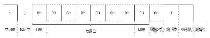
Data Frame Structure: Consists of a start bit, data bits, an optional parity bit, and stop bits.
2. Data Frame Structure:
3. Communication Modes:
-
Full Duplex: Can send and receive simultaneously (two independent channels).
-
Half Duplex: Sending and receiving cannot occur simultaneously.
-
Simplex: Data can only be transmitted in one direction.
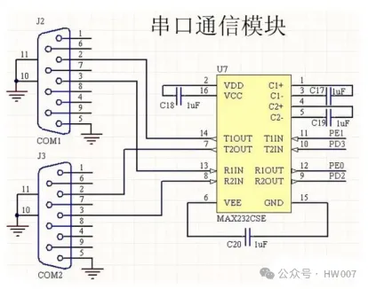
4. Implementation Methods:
-
Hardware Implementation: Achieved through MCU or dedicated UART chips (such as MAX232).
-
Software Implementation: Simulates UART communication through software, suitable for systems without hardware UART modules.
5. Applications:
-
Embedded Systems: Such as communication between microcontrollers and sensors, modules.
-
Computer Peripherals: Such as connections with mice, keyboards, modems, etc.
-
Debugging and Programming: Debugging embedded devices or downloading programs through the serial port.
4. IIC Communication?
I²C (Inter-Integrated Circuit) is a commonly used serial communication protocol designed for short-distance interconnection of low-speed devices. Developed by Philips (now NXP) in the 1980s, I²C is now widely used in embedded systems for connecting microcontrollers, sensors, displays, and other peripheral devices.
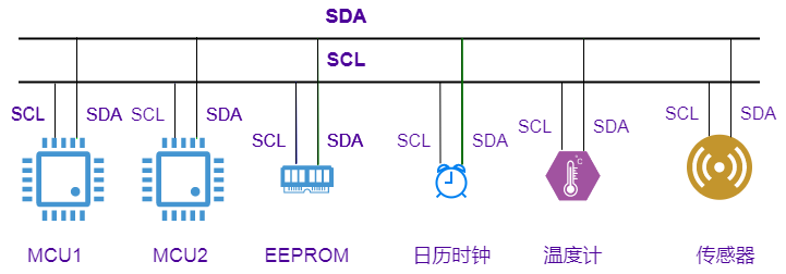
I²C Basic Concepts
I²C is a dual-wire serial bus system with a multi-master architecture, consisting of master and slave devices. Communication is conducted through two lines:
-
SCL (Serial Clock Line): Clock line generated by the master device.
-
SDA (Serial Data Line): Data line used for data transmission.
Data Transmission
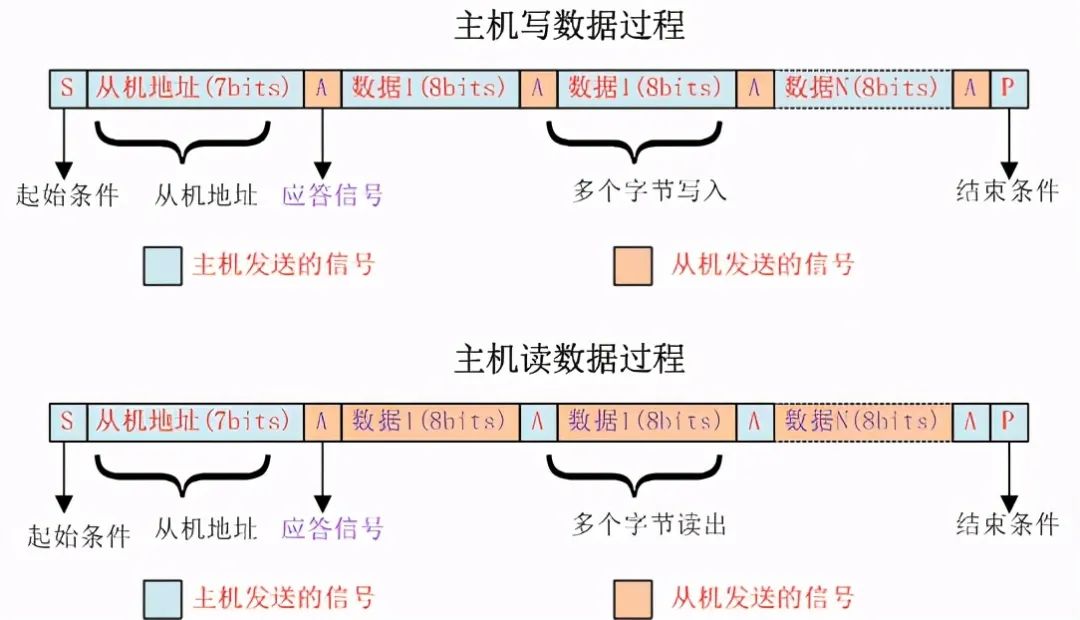
I²C uses 7-bit or 10-bit addresses for device addressing, transmitting data in bytes. The specific transmission steps are as follows:
-
Start Condition: The master device pulls the SDA line low and then pulls the SCL line low, indicating the start of communication.
-
Address Transmission: The master device sends the address of the slave device and indicates read/write operations.
-
Data Transmission: Data transmission occurs between the master and slave devices. Each byte is followed by an acknowledgment bit (ACK/NACK).
-
Stop Condition: The master device pulls the SCL line high and then pulls the SDA line high, indicating the end of communication.
I²C Device Address
Each I²C slave device has a unique 7-bit or 10-bit address. The 7-bit address is typically more widely used; during actual transmission, the address is left-shifted by one bit, with the rightmost bit indicating the read/write operation (0 for write, 1 for read).
I²C Communication Protocol
-
Start Condition: The master device pulls SDA from high to low while keeping SCL high.
-
Stop Condition: SDA is pulled from low to high when SCL is high.
-
Byte Data Transmission: After transmitting a byte of data, the receiver must send an acknowledgment bit (ACK).
-
Read/Write Operation: The master device sends the device address followed by a read/write bit, with 0 indicating write and 1 indicating read.
I²C Advantages
-
Simple Hardware Interface:Communication can be achieved with just two wires.
-
Multi-Master Architecture:Allows multiple master and slave devices to share a single bus.
-
Flexibility:Supports the use of multiple devices, and devices can be hot-swappable.
I²C Disadvantages
-
Lower Speed:The maximum speed in standard mode is 100kHz, with fast mode at 400kHz; higher speeds (up to 5MHz) require special high-speed modes.
-
Distance Limitations:Typically suitable for PCB internal or short-distance communication.
-
Bus Contention:When the bus is idle, multiple master devices may attempt to initiate communication simultaneously.
5. SPI Communication?
SPI Basic Concepts
-
MOSI (Master Out Slave In): Data output from the master device to the slave device. -
MISO (Master In Slave Out): Data input to the master device from the slave device. -
SCLK (Serial Clock): Clock line generated by the master device. -
SS/CS (Slave Select/Chip Select): Slave device selection line controlled by the master device to select a specific slave device.
Data Transmission
-
The master device drives the CS line low, selecting the slave device. -
The master device generates the SCLK clock signal. -
Data is synchronously transmitted via the MOSI and MISO lines. -
Data is sampled based on the rising or falling edge of the clock. -
After transmission is complete, the master device drives the CS line high, ending communication.
SPI Clock Phase and Polarity
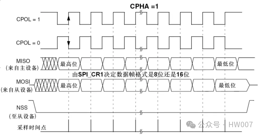
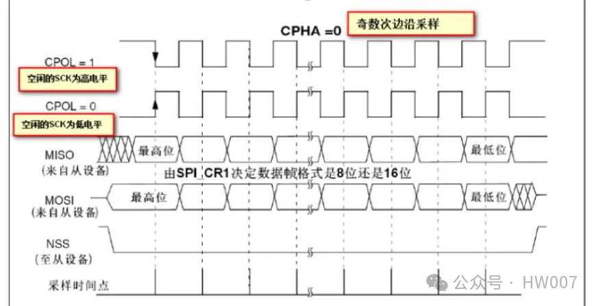
-
CPOL = 0, CPHA = 0: The clock signal is low when idle, sampling data on the first rising edge. -
CPOL = 0, CPHA = 1: The clock signal is low when idle, sampling data on the first falling edge. -
CPOL = 1, CPHA = 0: The clock signal is high when idle, sampling data on the first falling edge. -
CPOL = 1, CPHA = 1: The clock signal is high when idle, sampling data on the first rising edge.
SPI Advantages
-
High-Speed Transmission:Higher than I²C communication rates, suitable for high data rate transmission. -
Full Duplex Communication:Can send and receive data simultaneously. -
Simple Hardware Implementation:No complex arbitration mechanisms are needed.
SPI Disadvantages
-
More Lines Required:At least four lines are needed, increasing wiring complexity. -
Lack of Standardization:Different devices may have varying SPI implementations, requiring careful reading of device manuals.
6. RS-232 External Communication?
RS-232 (Recommended Standard 232) is a serial communication standard initially established by the EIA (Electronic Industries Association) in the 1960s. It is widely used for communication between computers and external devices (such as modems, printers, and industrial equipment). Although RS-232 is less used in modern consumer electronics, it remains very important in industrial automation and some specialized devices.
RS-232 Basic Concepts
RS-232 is a asynchronous serial, full duplex communication standard established by the Electronic Industries Association (EIA), one of the communication interfaces on personal computers, typically appearing with 9 pins (DB-9), and transmission distances usually range from several meters.
RS-232 Signals
The RS-232 interface defines several signal lines, the most commonly used are:
-
TXD (Transmit Data): Data transmission line.
-
RXD (Receive Data): Data reception line.
-
GND (Ground): Ground line.
-
RTS (Request to Send): Request to send.
-
CTS (Clear to Send): Clear to send.
-
DTR (Data Terminal Ready): Data terminal ready.
-
DSR (Data Set Ready): Data set ready.
-
DCD (Data Carrier Detect): Data carrier detection.
-
RI (Ring Indicator): Ring indicator.
RS-232 Electrical Characteristics
The signal voltage defined by RS-232 is as follows (negative logic):
-
Logic 1 (Mark): -3V to -15V.
-
Logic 0 (Space): +3V to +15V.
Any level between -3V and +3V is considered an uncertain state.
Data Transmission
RS-232 uses asynchronous communication without a clock signal. Data transmission is conducted through a data frame composed of start bits, data bits, optional parity bits, and stop bits:
-
Start Bit: Usually 1 bit, indicating the start of data transmission, logical low level.
-
Data Bits: Usually 5 to 8 bits, representing the actual data transmitted.
-
Parity Bit: Optional, used for error detection, generally includes odd parity and even parity.
-
Stop Bit: Usually 1 or 2 bits, indicating the end of a data frame, logical high level.
RS-232 Transmission Speed
The baud rate (transmission rate) of RS-232 can range from 300bps to 115200bps, with typical values including 9600, 19200, 38400, 57600, and 115200bps.
RS-232 Applications
RS-232 is widely used in:
-
Computer and Modems: Old-style dial-up internet.
-
Industrial Automation Equipment: Communication between PLCs, sensors, and controllers.
-
Embedded Systems: For debugging and communication.
-
Medical Devices: Such as data collection and monitoring devices.
7. RS485 Communication
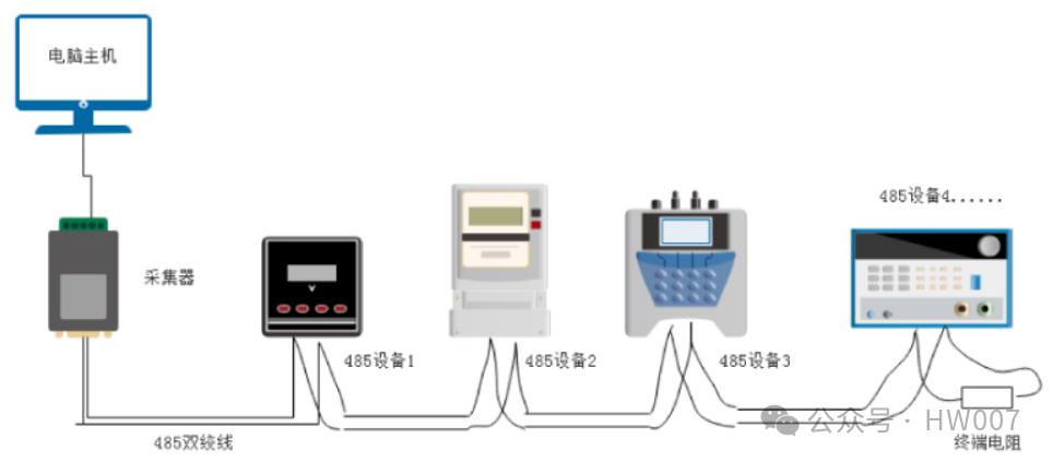
RS-485 is a serial communication standard for multipoint, differential signal transmission, widely applied in industrial automation, building automation, and other applications requiring reliable long-distance data transmission. Compared to RS-232, RS-485 has stronger anti-interference capabilities and longer transmission distances.
RS-485 Basic Concepts
Differential Signal
RS-485 uses differential signal transmission, transmitting data through two lines (A and B). The advantages of differential signals are:
-
Strong Anti-Interference Capability:Since the receiver detects the voltage difference between the two lines rather than the single-ended voltage, it has better resistance to noise.
-
Long Transmission Distance:Typical transmission distance can exceed 1200 meters.
Multipoint Communication
RS-485 supports multipoint communication, allowing multiple devices to connect on the same bus. A typical configuration is the master-slave mode, with up to 32 devices connected on one RS-485 bus, allowing more devices to connect using extenders.
RS-485 Electrical Characteristics
-
Logic 1: A line voltage lower than B line voltage, typically the voltage difference between the two lines is +(2~6)V.
-
Logic 0: A line voltage higher than B line voltage, typically the voltage difference between the two lines is -(2~6)V.
For drivers (transmitters), Logic 1 (positive) is A>B, with a voltage of +2~+6V between A and B, while Logic 0 (negative) is A<B, with a voltage of -2~-6V between A and B.
For receivers, Logic 1 (positive) is B>A, with a voltage of at least 200mV between B and A, while Logic 0 is A>B, with a voltage of less than -200mV between A and B, meaning positive and negative logic, with absolute voltage values both greater than 200mV.
RS-485 Communication Modes
Half Duplex
-
Data can only be transmitted in one direction, requiring protocol or hardware control to switch between sending and receiving.
-
Common connection: two differential lines (A and B), one ground line (GND).
Full Duplex
-
Data can be transmitted simultaneously in both directions, requiring four lines (two pairs of differential lines).
-
Common connection: four differential lines (A, B, Y, Z), one ground line (GND).
RS-485 Typical Applications
RS-485 is widely used in scenarios requiring long-distance, reliable transmission, such as:
-
Industrial Automation:Communication between PLCs, sensors, and actuators.
-
Building Automation:HVAC systems, access control, lighting control.
-
Serial Device Interconnection:For example, device communication under the Modbus protocol.
-
Remote Data Collection:Data collection in SCADA systems.
8. Modbus Protocol
Modbus Basic Concepts
-
Modbus RTU (Remote Terminal Unit):Based on binary transmission, typically used for RS-232, RS-485, and other serial communications. -
Modbus ASCII:Based on ASCII character transmission, also used for serial communication, but less commonly used. -
Modbus TCP/IP:Based on Ethernet communication, suitable for local area networks and internet environments.
Modbus Data Model
-
Discrete Inputs (Discrete Inputs):Read-only unit inputs (bits). -
Coils:Read-write unit outputs (bits). -
Input Registers:Read-only 16-bit inputs. -
Holding Registers:Read-write 16-bit registers.
Modbus Function Codes
-
Read Coils (0x01):Read the status of a group of coils. -
Read Discrete Inputs (0x02):Read the status of a group of discrete inputs. -
Read Holding Registers (0x03):Read the contents of a group of holding registers. -
Read Input Registers (0x04):Read the contents of a group of input registers. -
Write Single Coil (0x05):Write the state of a single coil. -
Write Single Register (0x06):Write the contents of a holding register. -
Write Multiple Coils (0x0F):Write the states of multiple coils. -
Write Multiple Registers (0x10):Write the contents of multiple holding registers.
Modbus Data Frame
-
Address Field (1 byte): Specifies the slave address. -
Function Code (1 byte): Specifies the operation type. -
Data Field (N bytes): Contains data for specific operations, such as register addresses, values, etc. -
Error Check Code (2 bytes): CRC check code for error detection.
9. CAN Bus
CAN Basic Concepts
Frame Types
-
Data Frame:Used to transmit actual data. -
Remote Frame:Requests to send a data frame. -
Error Frame:Reports detected errors. -
Overload Frame:Indicates bus overload.
Data Frame Structure
-
Start of Frame (SOF):Indicates the start of the frame. -
Identifier:Indicates the message’s priority and content. -
Standard Frame (11-bit identifier) -
Extended Frame (29-bit identifier) -
Control Field:Indicates data length and other control information. -
Data Field:The actual data being transmitted, with a length of 0 to 8 bytes. -
CRC Field:Cyclic Redundancy Check for error detection. -
Acknowledgment Field:Confirms whether the receiving end correctly received the sending end. -
End of Frame (EOF):Indicates the end of the frame.
Bit Arbitration
Error Detection
CAN Application Scenarios
-
Automotive Electronics:Body control, power systems, infotainment systems. -
Industrial Automation:Robot control, sensor data collection. -
Medical Devices:Real-time monitoring, diagnostic devices. Aerospace Electronics:Flight control systems.
The autumn recruitment has ended, and if everyone does not prepare adequately, it will be difficult to find good jobs in the spring.
Here’s a job package for everyone, you can prepare for the spring recruitment and find a good job!