Today, let’s discusshow to establish campus network virtualization.
Unlike traditional campus networks that focus on individual devices, virtualized networks emphasize the overall business experience across the entire network. By utilizing iMaster NCE-Campus and VXLAN technology, network resources can be flexibly allocated.
Through virtualization technology, physical network resources are pooled, creating a comprehensive resource pool that can be flexibly allocated by iMaster NCE-Campus.
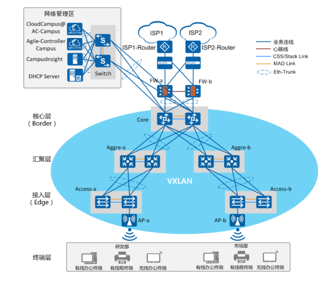
At the same time, multiple logically independent virtual networks can be created on a single physical network, each carrying different types of services and possessing relatively independent network resources. This achieves decoupling of services from the network, facilitating service management.
Virtualization technology retains the original hierarchical structure, data channels, and services provided in network design, ensuring that the end-user experience is equivalent to that of a dedicated physical network.
Multiple virtual networks sharing a single physical network can also improve resource utilization and reduce operational costs.
Let’s look at how to implement this.
If your work scenario requires a virtualization networking solution, this document is perfect for you. It is a 139-page PDF that thoroughly explains the process from data planning to deployment for campus virtualization.
01
Introduction to Campus Network Virtualization Solutions
Figure 1 shows the architecture of campus virtual networks. The Underlay represents the physical network layer, while the Overlay is the virtual network layer built on top of the Underlay using VXLAN technology.
Figure 1 Campus Virtualization Network Architecture
The Overlay consists of two parts: Fabric and VN.
Fabric: A pooled network abstracted from the Underlay network. When creating instantiated virtual networks (VN), network resources from the Fabric can be selected.
In the Fabric networking, further role division is made for VXLAN Tunnel Endpoints (VTEP):
01 Border
The border gateway node of the Fabric network corresponds to physical network devices, providing data forwarding between the Fabric network and external networks. Typically, a core switch that supports VXLAN is used as the Border.
02 Edge
The edge node of the Fabric network corresponds to physical network devices, where user traffic enters the Fabric network. Typically, access switches or aggregation switches that support VXLAN are used as Edge.
03 Virtual Network (VN)
A Virtual Network, which can be constructed as logically isolated virtual network instances (VN1, VN2 in the figure) by instantiating the Fabric.
Each VN corresponds to an isolated network (business network), such as a dedicated network for R&D.
02
Introduction and Comparison of Distributed Gateway Solutions for Network Virtualization
Networking 1 Distributed VXLAN Gateway, with core switches acting as integrated WAC, VXLAN to access
Layer 2 or 3 layer switches networking
VXLAN Roles: Core switches as Border, access switches as Edge
User Gateway: Wired user gateway at Edge, i.e., access switch; wireless user gateway at Border, i.e., core switch
Configuration Method:
-
Firewall: CLI/local Web management
-
Switch: CLI/iMaster NCE-Campus, preferably using iMaster NCE-Campus for configuration deployment
-
WAC: CLI/local Web management, local Web management redirects login through iMaster NCE-Campus
-
Wired Traffic: Enters VN from Edge, business policies executed at Edge
-
Wireless Traffic: Tunnel forwarding, traffic enters VN from Border (i.e., integrated WAC), business policies executed at Border
Networking 2 Distributed VXLAN Gateway, with aggregation switches acting as integrated WAC, VXLAN to aggregation
Layer 3 Switch Networking
VXLAN Roles: Core switches as Border, aggregation switches as Edge, access and aggregation deployment strategies linked
User Gateway: Edge, i.e., aggregation switch
Configuration Method:
-
Firewall: CLI/local Web management
-
Switch: CLI/iMaster NCE-Campus, preferably using iMaster NCE-Campus for configuration deployment
-
WAC: CLI/local Web management, local Web management redirects login through iMaster NCE-Campus
-
Wired Traffic: Enters VN from Edge, business policies executed at Edge.
-
Wireless Traffic: Tunnel forwarding, traffic enters VN from Edge (i.e., integrated WAC), business policies executed at Edge
Networking 3 Distributed VXLAN Gateway, core switch integrated WAC, VXLAN to aggregation
Layer 3 Switch Networking
VXLAN Roles: Core switches as Border, aggregation switches as Edge
User Gateway: Wired user gateway at Edge, i.e., aggregation switch; wireless user gateway at Border, i.e., core switch
Configuration Method:
-
Firewall: CLI/local Web management
-
Switch: CLI/iMaster NCE-Campus, preferably using iMaster NCE-Campus for configuration deployment
-
WAC: CLI/local Web management, local Web management redirects login through iMaster NCE-Campus
-
Wired Traffic: Enters VN from Edge, business policies executed at Edge.
-
Wireless Traffic: Tunnel forwarding, traffic enters VN from Border (i.e., integrated WAC), business policies executed at Border
Networking 4 Distributed VXLAN Gateway, core switch with independent WAC, VXLAN to aggregation
Layer 3 Switch Networking
VXLAN Roles: Core switches as Border, aggregation switches as Edge, access and aggregation deployment strategies linked
User Gateway: Wired user gateway at Edge, i.e., aggregation switch; wireless user gateway at Border, i.e., core switch
WAC Deployment VRRP Dual Machine Hot Backup Explanation:
Since the ports connecting the independent WAC to the Border will be configured for port isolation by default in iMaster NCE-Campus, when deploying VRRP dual machine hot backup for independent WAC, a direct heartbeat line must be deployed between the independent WACs. @Network Engineer Club
03
Detailed Deployment Ideas for Distributed Campus Network Virtualization Solutions
This section introduces the deployment ideas based on commonly used Layer 3 networking for distributed gateway solutions, where the aggregation switch acts as the Edge node and the core switch acts as the Border node.
The user gateway adopts a distributed deployment method, selecting the aggregation switch as the user gateway, as shown in Figure 2.
The specific networking explanation is as follows:
To ensure device-level reliability, the firewall adopts a VRRP active-standby dual machine hot backup, with core, aggregation, and access using stacked networking.
To ensure link-level reliability, Eth-Trunk networking is used between links.
The deployment of wireless services adopts a Fit AP+WAC architecture, with the core switch acting as the WAC device and AP devices operating in Fit AP mode.
The management layer components mainly involve iMaster NCE-Campus, iMaster NCE-Campus Insight, and DHCP servers.
Since the management layer components need to select the number of servers or virtual machine resources based on actual business needs, please refer to the specifications required in the product manuals of each management layer component. In this case, the data planning for each component is based on smaller configuration specifications. @Network Engineer Club
The servers for installing management layer components connect to the campus network through stacked switches (Switch as the Layer 3 gateway for the network management area), and each server uses dual network cards bound into a Bond interface (this group binding mode adopts load balancing), then connects to the Eth-Trunk interface of the Switch, as shown in Figure 4-2.
If the management layer components are deployed in a data center, the server-side networking can refer to the data center network solution.
The wiring requirements for servers installing each management layer component to the data center switch can refer to the product manuals of each management layer component.
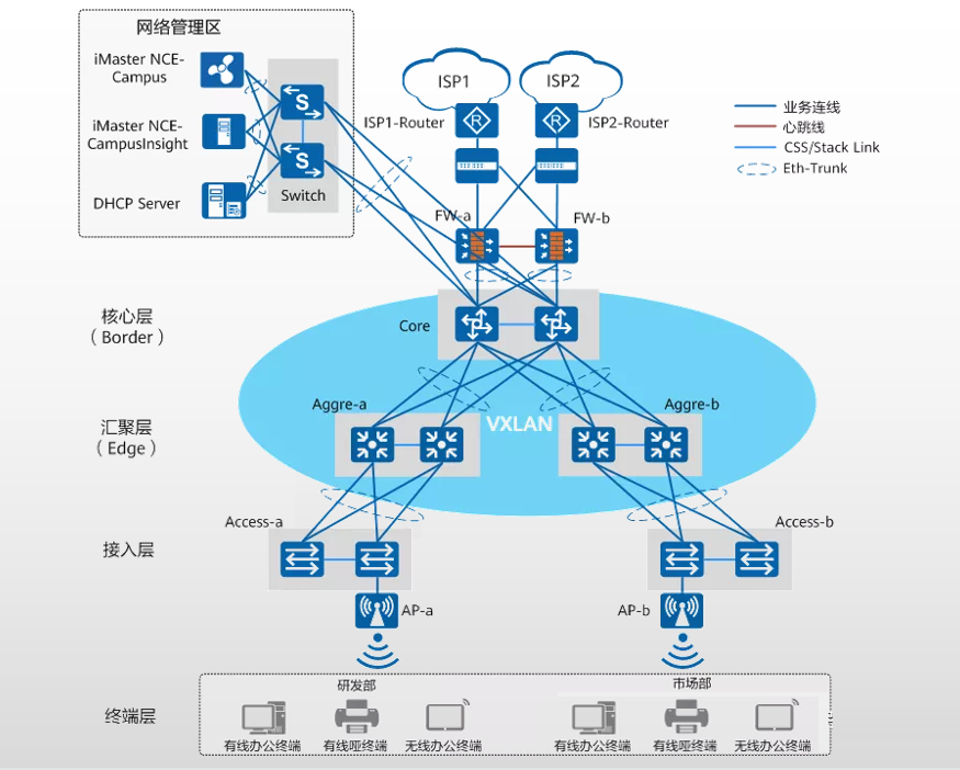
Figure 2 Networking Diagram for Distributed Gateway Scenario in Large and Medium-sized Campuses (Aggregation as Edge and User Gateway, Core as Border)
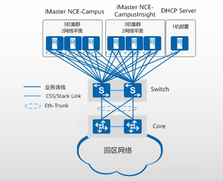
Figure 3 Physical Server Deployment Networking in the Network Management Area
04
Best Practices for Deploying Distributed Campus Network Virtualization Solutions
This section introduces detailed deployment practices for the distributed gateway solution of campus network virtualization based on the main networking introduction and comparison of commonly used Networking 3.
The specific networking is a Layer 3 physical network with VXLAN to aggregation, using the WAC as the Border device (i.e., core switch). @Network Engineer Club
01 Specific Networking Situation
Layer 3 physical networking, Fabric using VXLAN to aggregation.
Border device (i.e., core switch) acts as integrated WAC.
Edge devices serve as wired user gateways; Border devices serve as wireless user gateways.
02 Overall Data Planning
Each server installing components in the network management area uses dual network cards bound together, then connects to the stacked Switch. The data planning for each component’s communication with the core switch is shown in Figure 4;
The overall planning of IP addresses, VLANs, and other resources for each component during deployment is shown in Table 5-1, with more detailed deployment data planning introduced in the subsequent sections for each component.
Among them:
The gateway for components in the network management area is the Switch, which communicates with the Core through Layer 3 routing.
VLAN 4009 is used for communication between iMaster NCE-Campus southbound, iMaster NCE-Campus Insight southbound, and the management subnet.
VLAN 4012 is used for communication between iMaster NCE-Campus southbound, DHCP server, and user subnet. @Network Engineer Club
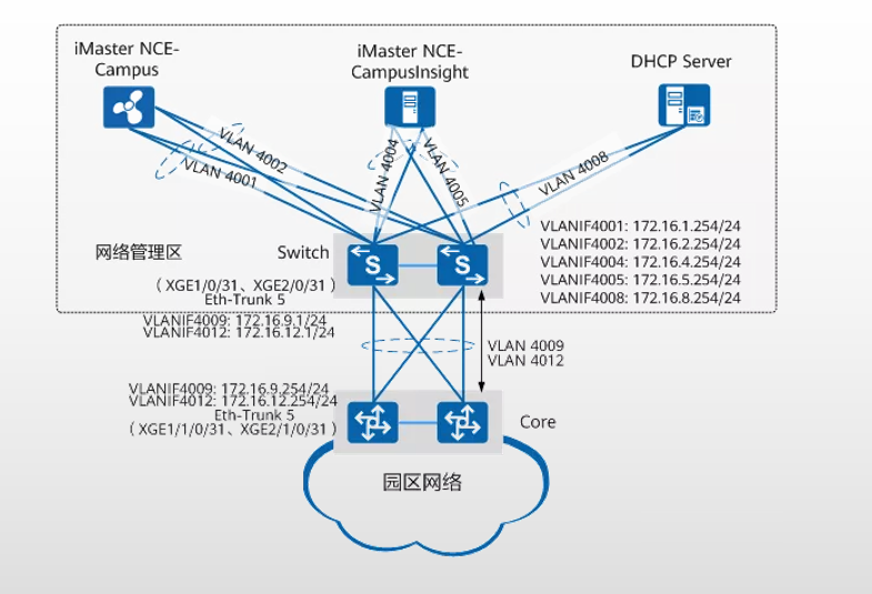
Figure 4 Data Planning for Communication between Network Management Area Components and Core Switch
03 Physical Link Data Planning
As shown in Figure 5, the physical link planning for large and medium-sized campus virtualization solutions is not marked in the diagram for the communication link between the network management area and the core switch. Please refer to the overall data planning in the previous section “Data Planning for Network Management Area Components”.
In this case, the creation method for aggregation links between different campus network devices is as follows:
Aggregation links between access, aggregation, and core switches: Import aggregation link information in bulk to the site using the template in “Import Network Planning”.
Aggregation links between the core switch and the network management area gateway: Manually create on the device using command line on both the core switch side and the network management area gateway side.
Aggregation links between the core switch and the firewall:
On the core switch side, manually create using iMaster NCE-Campus, and on the firewall side, manually create using its Web management.
04 Device Management Data Planning
As shown in Figure 6, in this case, the core switch enables NETCONF functionality via command line, configuring the southbound address and port number for iMaster NCE-Campus to 172.16.2.5:10020, with the interface for southbound connection being VLANIF4009, and the IP address being 172.16.9.254/24.
After iMaster NCE-Campus manages the core switch, two management subnets are configured on the core switch, one for managing aggregation/access switches and one for managing APs.
Independent self-negotiating management VLANs are used for communication between the core switch and aggregation/access switches, and between the core switch and APs.
The wired self-negotiating management VLAN is VLAN 4080, with the address pool interface being VLANIF4080 (IP address 192.168.100.254), and the function of enabling Option 148 carrying the southbound address of iMaster NCE-Campus (the address does not need to be manually configured, it is automatically negotiated); @Network Engineer Club
The wireless self-negotiating management VLAN is VLAN 4090, with the address pool interface being VLANIF4090 (192.168.200.254), and the function of enabling Option 43 carrying the WAC address, with the WAC address being 192.168.200.254.
If the aggregation/access switches require fixed IP addresses for access in subsequent operations and maintenance management, the function of fixing the management address can be enabled when configuring the management subnet.
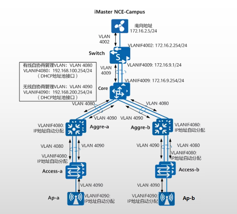
Figure 6 Management Network Data Planning from Access Layer to Core Layer
05 User Subnet Data Planning
The Underlay is the physical network layer that carries the upper-layer virtual network and needs to ensure routing reachability; the Overlay is the virtual network layer built on top of the physical network layer using VXLAN technology.
The Overlay consists of Fabric and VN, where Fabric is equivalent to constructing a pooled network, and VN can select resources from Fabric as needed during construction;
Creating a VN (Virtual Network) is equivalent to instantiating the Fabric, where a VN instance can represent a dedicated virtual network for a business, such as RD_VN representing the R&D department network, and Market_VN representing the marketing department network.
The Border and Edge nodes of the Fabric network are VTEP nodes (VXLAN Tunnel Endpoints). @Network Engineer Club
In this case, the Fabric network with distributed gateways has the core switch as the Border node serving as the wireless user gateway;
and the aggregation switch as the Edge node serving as the wired user gateway.
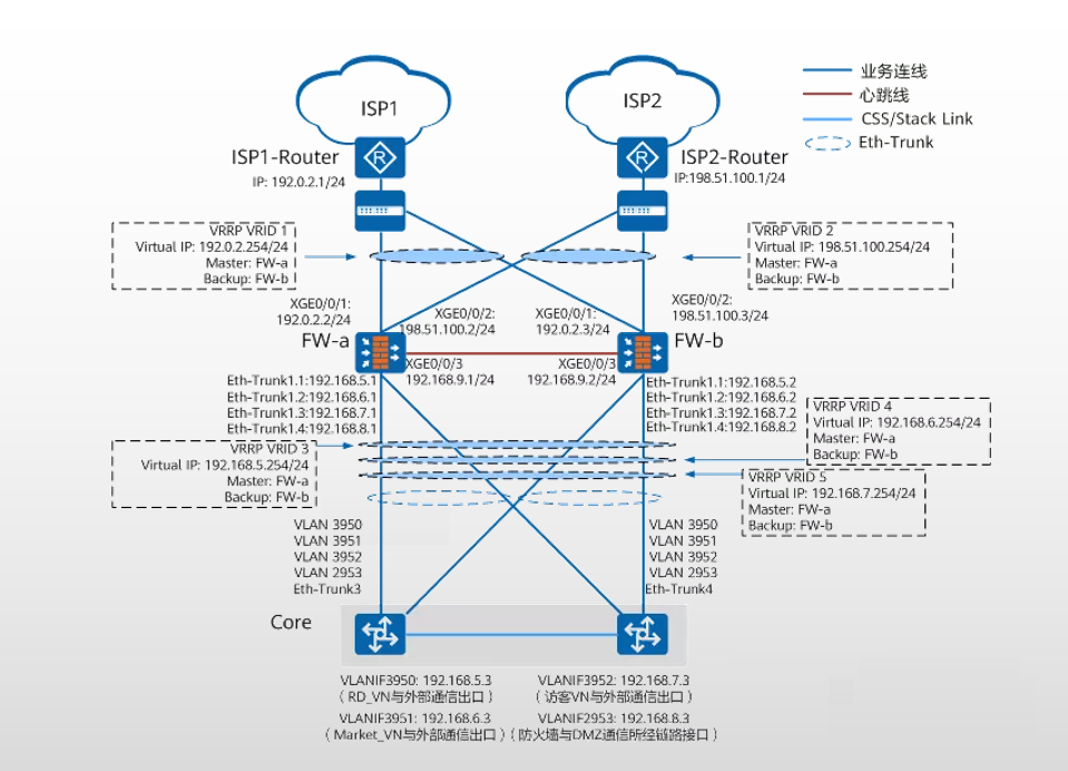
Figure 7 Layered Diagram of Underlay and Fabric
06 Exit Network Data Planning
The Border node in the Fabric network (i.e., Core device) uses L3 exclusive exit to connect to the exit firewall device, meaning each VN has a corresponding Layer 3 interface connecting to the firewall’s security zone, enabling external access.
The guest network also has a corresponding Layer 3 interface connecting to the firewall’s security zone, enabling external access.