After the chip is powered on and reset, the first program executed is referred to as Bootrom loader within the chip. This part of the program is hardcoded into the internal ROM space of the chip during the manufacturing process, has read-only attributes, and cannot be modified during actual use. The intellectual property rights of this program belong solely to the chip company. In fact, you can also refer to Bootrom loader as firmware.
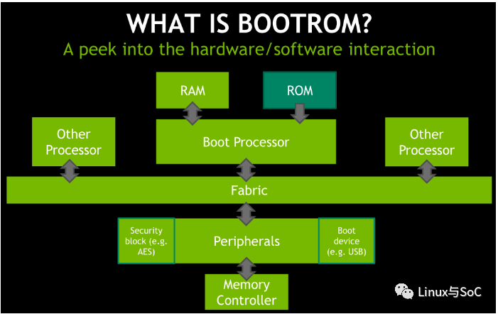
For ARM architecture processors, the PC after the chip is powered on and reset usually points to the address 0x00000000 or 0xffff0000. This means it will fetch the first instruction from that address, decode, and execute it. The boot modes supported by the CPU are informed to the CPU through hardware dip switches, and the internal logic of the CPU will recognize the bootmode after power-on reset. Based on the recognized bootmode, it decides where to fetch the first instruction. If it is determined after parsing bootmode that it is not booting from bootrom but from other storage peripherals such as norflash, nandflash, qspiflash, etc., these peripherals will become the primary boot devices for the CPU, and the internal logic of the CPU will remap the address space of these boot peripherals.
The RK3399 contains 4 ARM Cortex-A53 and 2 Cortex-A72 cores, forming a typical cluster structure, with Cortex-A53 as the little core and Cortex-A72 as the big core. After the system is powered on and reset, core0 of Cortex-A53 is the first core to boot, executing the Bootrom loader program at 0xffff0000.
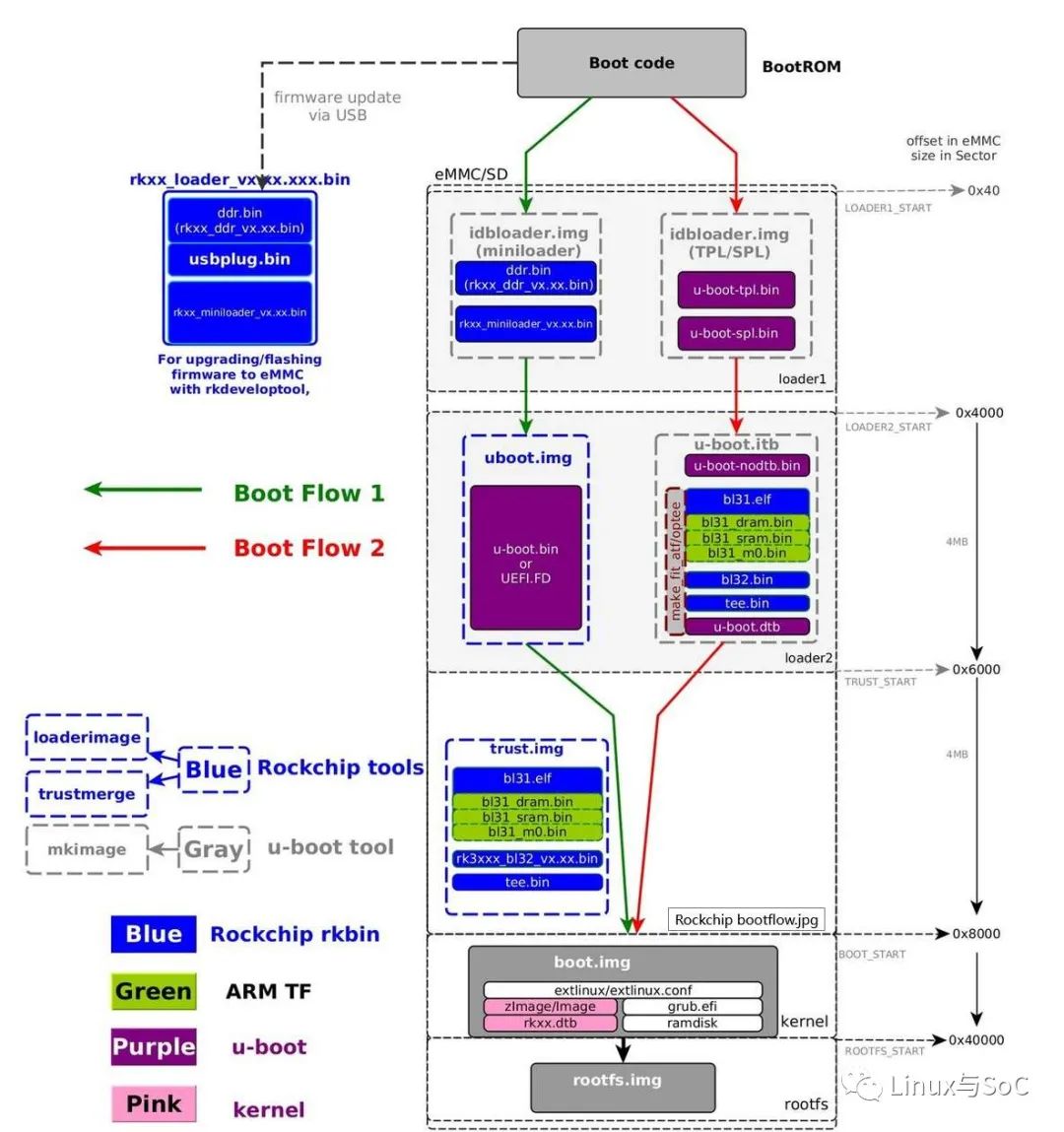
The complete boot process is shown in the diagram below:
+--------+----------------+----------+-------------+---------+
| Boot   | Terminology #1 | Actual   | Rockchip    | Image   |
| stage  |                | program  |  Image      | Location|
| number |                | name     |   Name      | (sector)|
+--------+----------------+----------+-------------+---------+
| 1      |  Primary       | ROM code | BootRom     |         |
|        |  Program       |          |             |         |
|        |  Loader        |          |             |         |
|        |                |          |             |         |
| 2      |  Secondary     | U-Boot   |idbloader.img| 0x40    | pre-loader
|        |  Program       | TPL/SPL  |             |         |
|        |  Loader (SPL)  |          |             |         |
|        |                |          |             |         |
| 3      |  -             | U-Boot   | u-boot.itb  | 0x4000  | including u-boot and atf
|        |                |          | uboot.img   |         | only used with miniloader
|        |                | ATF/TEE  | trust.img   | 0x6000  | only used with miniloader
|        |                |          |             |         |
| 4      |  -             | kernel   | boot.img    | 0x8000  |
|        |                |          |             |         |
| 5      |  -             | rootfs   | rootfs.img  | 0x40000 |
+--------+----------------+----------+-------------+---------+
The secondary boot devices for the RK3399 support SPI NOR FLASH, SPI NAND FLASH, eMMC, SD, and USB load. The secondary boot program can be placed in the above-mentioned static storage devices, and RK3399 determines whether the current boot program is valid by reading the ID BLOCK information.
RK3399 provides a software tool AndroidTool.exe for updating image files, which can update the secondary boot program and all subsequent images.
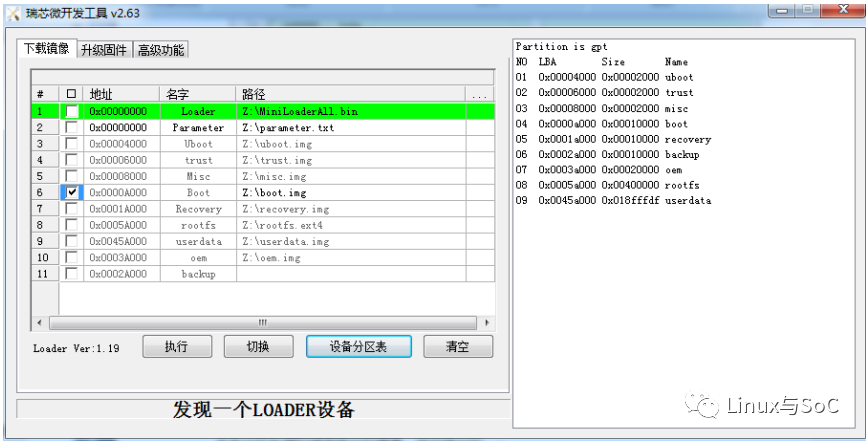
The method for entering firmware update mode depends on the design of the board. For example, for the board we have, the firmware update mode can be entered as follows:
Connect the development board to the host using a Type-C cable, hold down the recover button without releasing it, then press the reset button to reset the system. After about two seconds, release the recover button. The system will prompt that the loader device has been detected.
Recommended Reading:Collection | Summary of Linux ArticlesCollection | Programming LifeCollection | C LanguageMy Knowledge CircleFollow the public account, reply ‘1024’ to get the link to learning materials on the cloud disk.Thank you for liking, following, sharing, and viewing. Every encouragement you give will be remembered! Embedded LinuxScan the QR code to follow my public account