1. Address Space
1.1 Accessing Registers in ARM
How do you access registers in ARM? Just like accessing memory: how to access a register? Use a pointer:
int   a;  unsigned int *p  = &a;   // p equals "address of a"
*p = val;   // Writing to this address means writing to a
val = *p;   // Reading from this address means reading a
unsigned int *p = 0x40010800; // p equals the address of a certain register
*p = val; // Writing to this address means writing to this register
val = *p; // Read from the register1.2 Differences Between ARM and X86
In the view of ARM and CPU, memory and IO operations are the same:
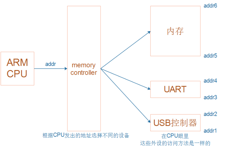
The address sent by the CPU allows it to directly access the corresponding peripherals. These peripherals’ addresses belong to the CPU’s address space, but in the above image, the address sent by the CPU cannot reach Flash. If the CPU wants to access Flash, it must go through the EMMC controller, as Flash belongs to another address space, divided into several family relationships, meaning it can only be accessed in a generational manner, not across generations.
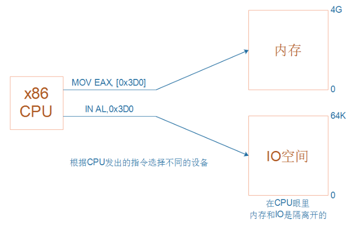
In the X86 architecture, memory and IO are separated:
1.3 RISC vs. CISC
1.3.1 RISC
ARM chips belong to RISC (Reduced Instruction Set Computing), which uses simpler instructions with the following characteristics:
① Only read and write instructions for memory
② Data operations are implemented within the CPU
③ CPUs using RISC instructions have slightly lower complexity, making them easier to design

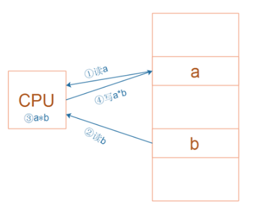
For the multiplication operation shown in the above image a = a * b, in RISC, four assembly instructions are required:
① Read memory a
② Read memory b
③ Calculate a*b
④ Write the result back to memory
1.3.2 CISC
X86 belongs to CISC (Complex Instruction Set Computing), which uses more complex instructions. For instance, some complex instructions are implemented via “microprograms”.
For example, when executing a multiplication instruction, it actually executes a “microprogram” that performs the same four operations:
① Read memory a
② Read memory b
③ Calculate a*b
④ Write the result back to memory
The above operations may seem straightforward to the programmer, as they appear to accomplish everything with a single instruction!
1.3.3 Comparison of RISC and CISC
-
CISC has strong instruction capabilities, but most instructions are used infrequently, increasing CPU complexity; instructions are of variable length;
-
RISC instructions are mostly single-cycle instructions, fixed length, and operate on registers, with only Load/Store operations for memory;
-
CISC supports various addressing modes; RISC supports various addressing modes;
-
CISC is implemented through microprogram control technology;
-
RISC increases general-purpose registers, primarily using hardwired logic control, and employs pipelining;
-
CISC has a long development cycle;
-
RISC optimizes compilation, effectively supporting high-level languages;
2. ARM Internal Registers
2.1 Internal Registers of the CPU
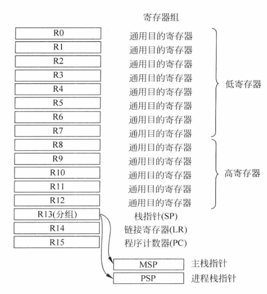
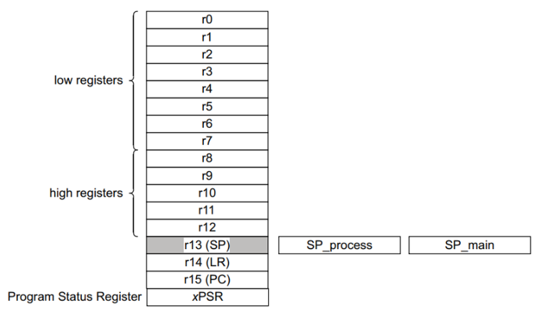
Whether it’s cortex-M3/M4 or cortex-A7, the CPU has registers R0, R1, …, R15; they can be used to “temporarily store” data.
-
Registers R0–R12 are general-purpose registers, with the first eight (R0–R7) also known as low registers. Due to limited space in instructions, many 16-bit instructions can only access low registers. High registers (R8–R12) can be used for 32-bit instructions and several 16-bit instructions, such as MOV (move). The initial values of R0–R12 are undefined.
-
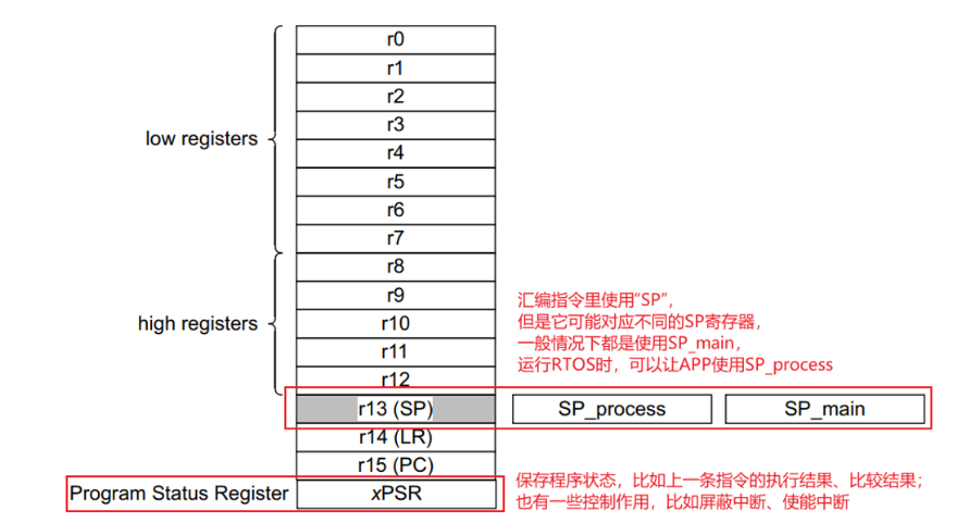
R13 is the stack pointer, allowing access to stack storage via PUSH and POP operations. There are physically two stack pointers: the main stack pointer (MSP, sometimes referred to as SP_main in some ARM literature) is the default stack pointer, used by the processor after reset or when in handling mode. The other stack pointer is called the process stack pointer (PSP, sometimes referred to as SP_process in some ARM literature), which can only be used in thread mode. The choice of stack pointer is determined by a special register CONTROL, described in section 4.2.3. For general programs, only one of these two registers will be visible. Both MSP and PSP are 32-bit, but the lowest two bits of the pointer (MSP or PSP) are always 0, and writing to these two bits has no effect. For ARM Cortex-M processors, PUSH and POP are always 32-bit, and the addresses for stack operations must also be aligned to 32-bit word boundaries.
-
R14 is also known as the link register (LR), used to save the return address during function or subroutine calls. At the end of a function or subroutine, program control can return to the calling program by loading the value of LR into the program counter (PC) and continuing execution. After a function or subroutine call, the value of LR is automatically updated. If a function needs to call another function or subroutine, it must first save the value of LR onto the stack; otherwise, the current value of LR will be lost after the function call.
-
R15 is the program counter (PC), which is readable and writable, reading returns the current instruction address plus 4 (due to the design of the pipeline feature and compatibility with the ARM7TDMI processor). Writing to PC (for example, using data transfer/processing instructions) will cause a jump operation. (Indicating the current instruction address, writing a new value will cause a jump)
2.2 Classification of Internal CPU Registers
Cortex-M3/M4:
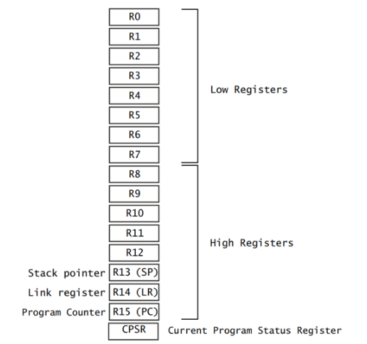
For comparison, cortex-A7 is similar:
2.3 Example
When comparing two numbers, how different CPU registers handle it: for cortex-M3/M4, there is also a Program Status Register
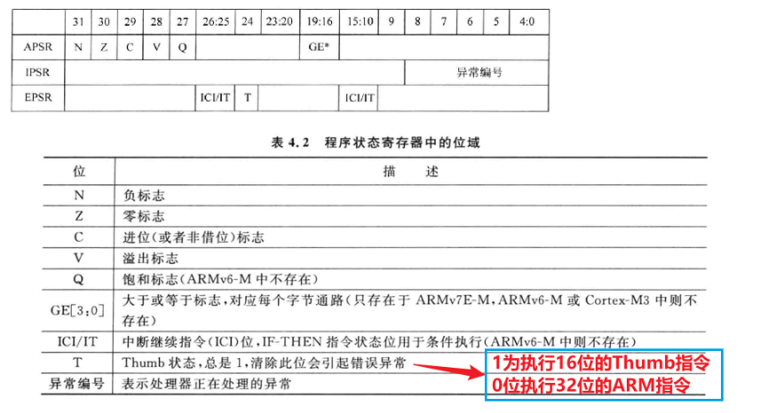
For cortex-M3/M4, xPSR actually corresponds to three registers:
① APSR: Application PSR
② IPSR: Interrupt PSR
③ EPSR: Execution PSR
The meanings of these three registers are shown in the following image:
These three registers can be accessed individually:
MRS  R0, APSR  ; Read APSR
MRS  R0, IPSR    ; Read IPSR
MSR  APSR, R0   ; Write APSR
These three registers can also be accessed all at once:
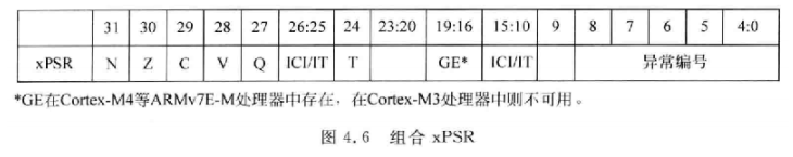
MRS  R0,  PSR  ; Read combined program status
MSR  PSR, R0   ; Write combined program status
The so-called combined program status is shown in the following image:
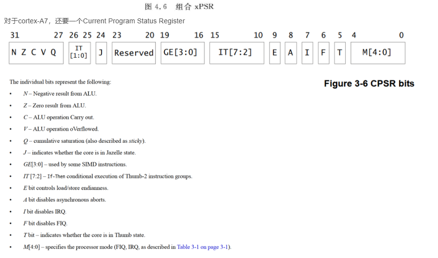
For cortex-A7, there is also a Current Program Status Register
3. ARM Assembly
3.1 Overview
Initially, ARM released two types of instruction sets:
① ARM instruction set, which is 32-bit, with each instruction occupying 32 bits, efficient but takes up too much space
② Thumb instruction set, which is 16-bit, with each instruction occupying 16 bits, saving space
Use Thumb instructions when saving space, and ARM instructions when efficiency is needed.
A CPU can run both Thumb and ARM instructions.
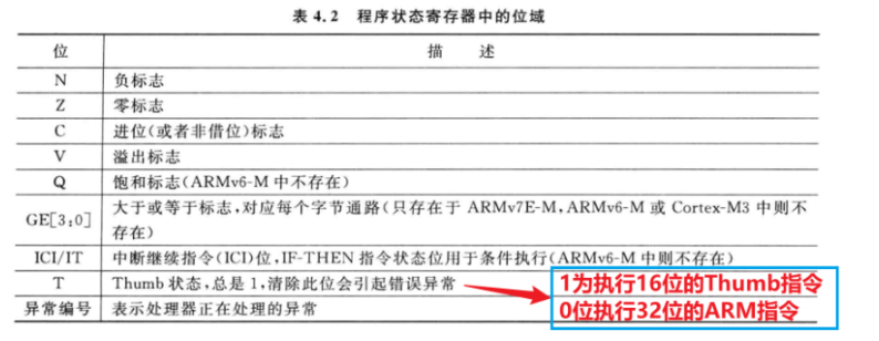
How to distinguish whether the current instruction is a Thumb or ARM instruction?
There is a bit in the program status register called “T”; when it equals 1, it indicates that the current instruction being executed is a Thumb instruction.
We can write the address of function A or B into the PC register to call A or B, but how do we make the CPU enter Thumb state when executing function A and ARM state when executing function B?
When calling function A, set BIT0 of the PC register to 1, that is: PC = address of function A + (1<<0);
When calling function B, set BIT0 of the PC register to 0: that is: PC = address of function B
In daily work, only a few assembly instructions are needed, and their meanings can be guessed from their names:
MOV LDR/STR LDM STM AND/OR ADD/SUB B LD C D ADR/LDR CMP3.2 Assembly Instruction Format
Refer to “DEN0013D_cortex_a_series_PG.pdf” P70 and “ARM Cortex-M3 and Cortex-M4 Authority Guide.pdf” Chapter 5

Assembly instructions can be divided into several categories: data processing, memory access, jumps, saturation operations, and other instructions. For example, the UAL assembly format for “data processing” instructions is:
Operation{cond}iS} Rd, Rn, Operand2 -
Operation represents various assembly instructions, such as ADD, MOV;
-
cond represents the condition under which the instruction executes;
-
S indicates that the instruction will modify the program status register;
-
Rd is the destination register used to store the result of the operation;
-
Rn and Operand2 are the two source operands. Operation represents various assembly instructions, such as ADD, MOV; as shown in the following image:
cond can take various values, as shown below:
3.3 Branch/Jump Instructions
Refer to “DEN0013D_cortex_a_series_PG.pdf” P327, P328, P329
Core instructions are B, BL: B: Branch, jump; BL: Branch with Link, save the return address in LR before jumping; BX: Branch and eXchange, switch to ARM or Thumb state based on BIT0 of the jump address (0: ARM state, 1: Thumb state); BLX: Branch with Link and eXchange, switch to ARM or Thumb state based on BIT0 of the jump address (0: ARM state, 1: Thumb state)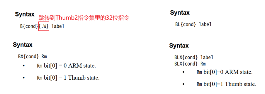
3.4 Immediate Values
This instruction: MOV R0, #VAL intends to store the value of VAL in register R0.
Question: Can VAL be any value?
Answer: No, it must be an immediate value.
Question: Why?
Answer: If VAL could be any number, “MOV R0, #VAL” itself is 16 or 32 bits, where would the space be to store any value of VAL?
Therefore, VAL must meet certain specifications.
3.5 LDR Pseudo Instruction
It can be cumbersome to determine whether a VAL is an immediate value!
And if I just want to assign any value to R0, what should I do?
I can use the pseudo-instruction: LDR R0, =VAL
“Pseudo-instruction” means it’s a fake, non-existent instruction.
Note that LDR as a “pseudo-instruction” has an “=”, otherwise it’s the real LDR (load register) instruction.
There are two cases (divided into immediate and non-immediate):
The compiler will replace the “pseudo-instruction” with the real instruction, for example:
LDR R0, =0x12 0x12 is an immediate value, so it is replaced with:
MOV R0, #0x12LDR R0, =0x123456780x12345678 is not an immediate value, so it is replaced with:
LDR R0, [PC, #offset] // 2. Use Load Register to read the memory instruction, offset is determined at link time……Label DCD 0x12345678 // 1. The compiler saves this value somewhere in the program3.6 ADR Pseudo Instruction
ADR means address, used to read the address of a certain label
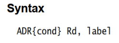
Example:
ADR  R0,  Loop
Loop    ADD  R0, R0, #1
It is a “pseudo-instruction” that will be converted into a real instruction, for example:
ADD R0, PC, #val   ; val is determined at link time
Loop    ADD  R0, R0, #1
3.7 Differences Between ARM Compiler and GCC Compiler Syntax
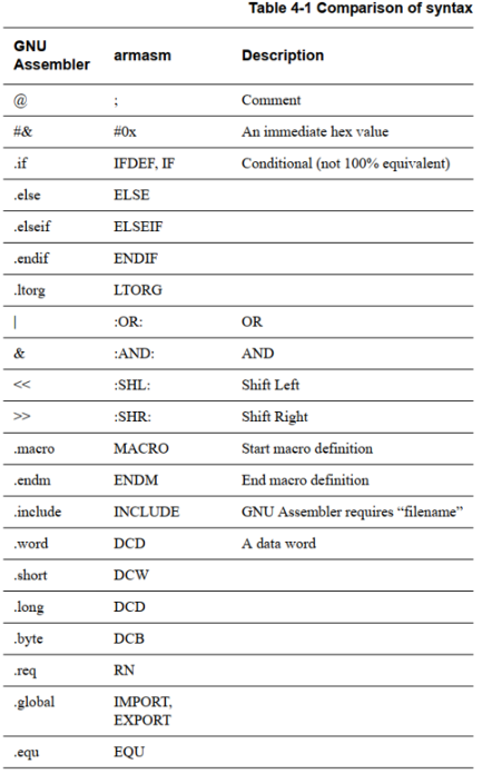
4. ARM Assembly Simulator
4.1 Simulator VisUAL
VisUAL is an ARM assembly simulator,
Download link:
https://salmanarif.bitbucket.io/visual/downloads.html
Usage method:
https://salmanarif.bitbucket.io/visual/user_guide/index.html
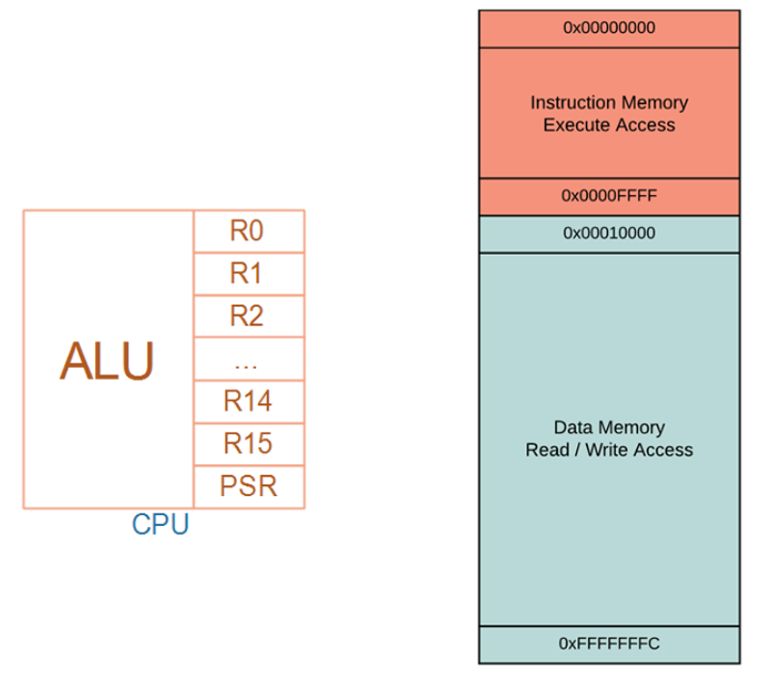
The ARM board simulated by VisUAL is shown in the image below; it does not simulate peripherals, only simulates CPU, ROM, RAM.
-
The red area is ROM, read-only, can only run programs within it;
-
The ROM area could originally be readable, this is a limitation of VisUAL;
-
The RAM area is readable and writable.
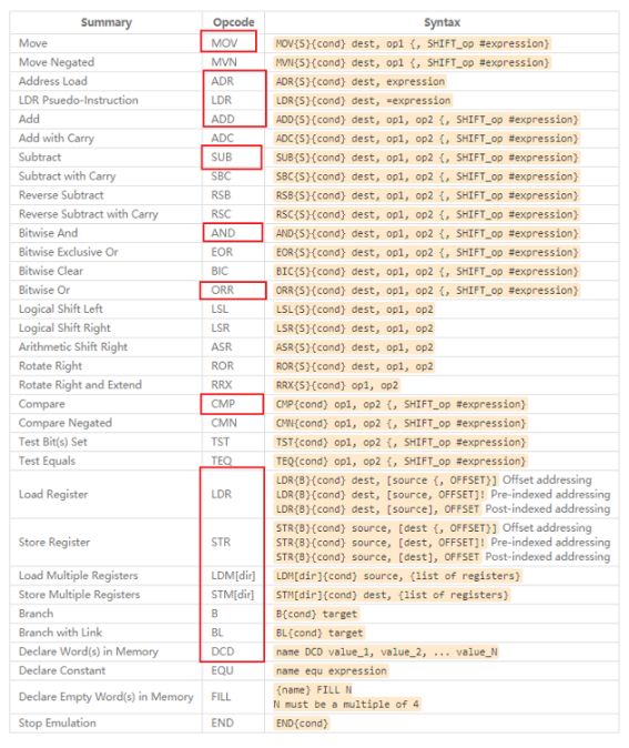
4.2 Supported Assembly Instructions in VisUAL
Note: DCD, FILL, END, etc., in the image below are ARM assembler syntax, which differs slightly from GCC assembly syntax, as will be introduced later.
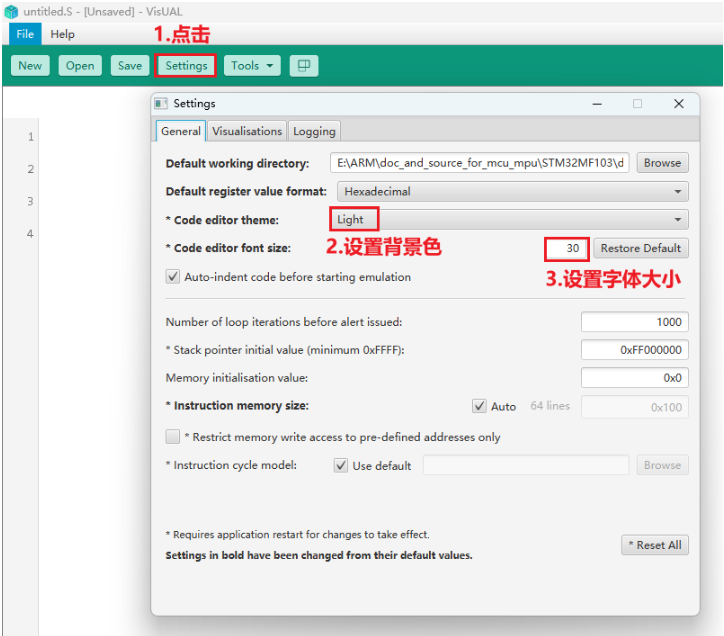
4.3 VisUAL Settings
Generally, no settings are needed; I only set the font size and background color: after setting the size, you must press enter for it to take effect.
4.4 Writing Assembly Instructions
Enter assembly code in the left code column:
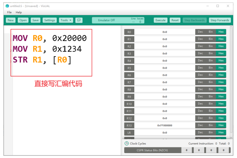
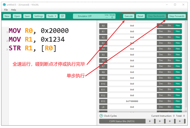
Run:
However, there are certain issues in the above assembly program:
① The 0x20000 in the first instruction is not an immediate value; modify it to be an immediate value;
② The 0x21234 in the second instruction is not an immediate value; modify it to be an immediate value;
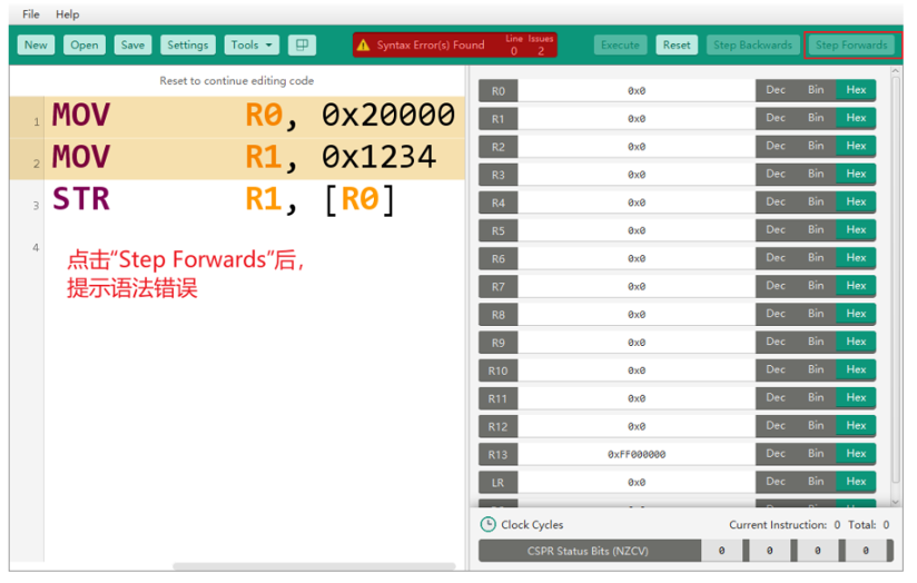
Modify the errors:
Click “Reset” and modify it to:
MOV R0, #0x20000
MOV R1, #0x1234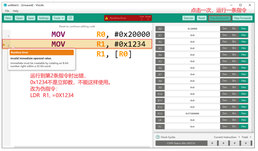
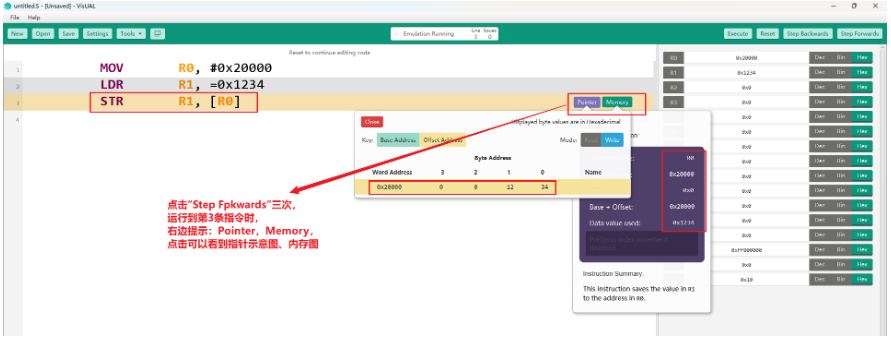
Check pointers and memory:
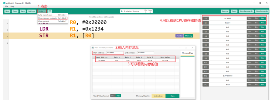
Tools can be used to view the memory values at memory addresses:
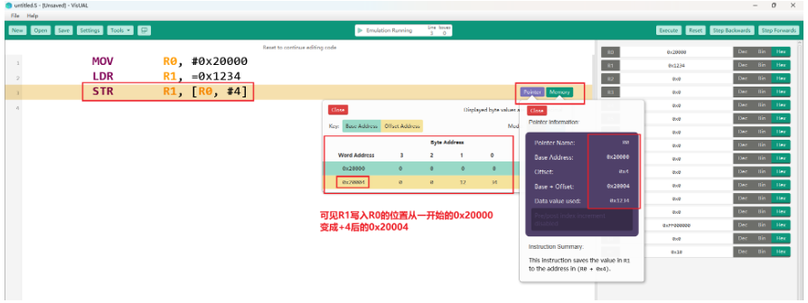
Modify the above assembly code to let R1 be stored at R0+4, and view the pointer diagram and memory diagram:
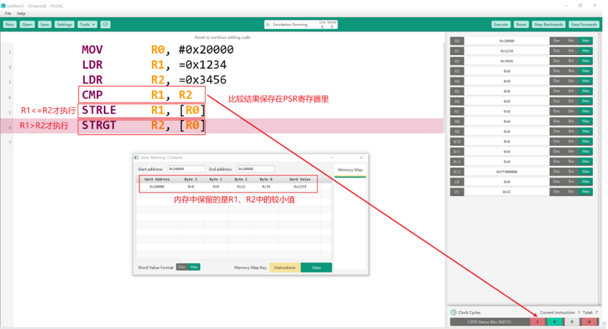
We can also write slightly more complex assembly programs:
This article has eight chapters; due to length, more exciting content can be accessed by clicking the bottom left corner “Read Original”!
Recruitment Requirements
Complete high-quality video production related to robots
Total duration must reach over 3 hours
Video content must be high-quality courses, ensuring high quality and professionalism
Instructor Rewards
Enjoy course revenue sharing
Receive 2 courses from GuYue Academy’s premium courses (excluding training camps)
Contact Us
Add staff WeChat: GYH-xiaogu