Tang Jianqiang, Zhou Fengxing, Shen Chunpeng
(Wuhan University of Science and Technology, School of Information Science and Engineering, Wuhan, Hubei 430081)
Abstract: In response to the premature failure of 12 V on-board battery power systems, a battery condition monitoring and intelligent control system based on μC/OS-II has been designed. This system integrates flyback switch power supply technology, μC/OS-II multitasking management, digital PI controllers, and PWM modulation techniques to achieve unified management of the battery charging and discharging processes, effectively avoiding undercharging, overcharging, and excessive discharge of the battery. Additionally, a method using least squares fitting of partial discharge curves to obtain first-order coefficients for assessing the battery’s lifespan and performance is proposed. Experiments show that the system has good real-time performance and reliability, providing an excellent solution for battery maintenance and management.
Keywords: Intelligent control and monitoring; Flyback switch power supply; Multitasking management; Multi-stage charging strategy; Lifespan assessment and prediction
Chinese Classification Number: TM912
Document Identification Code: A
DOI: 10.16157/j.issn.0258-7998.2017.07.037
Chinese Citation Format: Tang Jianqiang, Zhou Fengxing, Shen Chunpeng. Battery condition monitoring and intelligent control system based on μC/OS-II[J]. Application of Electronic Technique, 2017, 43(7): 148-152, 156.
English Citation Format: Tang Jianqiang, Zhou Fengxing, Shen Chunpeng. Battery condition monitoring and intelligent control system based on μC/OS-II[J]. Application of Electronic Technique, 2017, 43(7): 148-152, 156.
1 Introduction
Batteries are widely used in various industrial fields and daily life, and their lifespan is closely related to undercharging, overcharging, and excessive discharge. Effectively ensuring and improving battery lifespan is a pressing issue in battery management system design.
The design of battery management systems mainly focuses on charging and discharging. Different application scenarios adopt different charging and discharging control strategies. Currently, the charging strategy mainly uses three-stage charging, while pulse charging is a popular research area aimed at avoiding undercharging and overcharging of batteries; the discharging strategy mainly sets threshold voltages to prevent excessive discharge.
This paper designs a battery condition monitoring and intelligent control system based on μC/OS-II for the specific research subject. The system adopts multitasking design to maintain and manage the 12 V on-board battery. The design comprehensively applies μC/OS-II real-time multitasking management, flyback switch power supply technology, digital PI controllers, and pulse width modulation (PWM) technology to analyze the changes in voltage and current during the battery’s operation and reasonably control the battery’s working process, thus ensuring and improving the battery’s cycle lifespan, which has significant implications for the development of battery application technologies.
1.1 System Structure and Working Principle
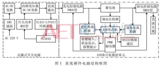
The battery condition monitoring and intelligent control system is mainly composed of two parts: the flyback switch power supply and the AVR microcontroller digital control circuit. The flyback switch power supply converts mains power into low-voltage DC for charging the battery, while the AVR microcontroller digital control circuit achieves real-time and efficient unified control of the battery’s charging and discharging processes. Figure 1 shows the overall structure diagram of the hardware circuit.
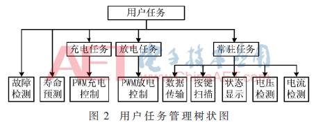
The software design adopts the μC/OS-II operating system kernel ported to the AVR microcontroller to achieve multitasking management. Figure 2 shows the tree diagram of user task management.
1.1.1 Flyback Switch Power Supply Design
The specific design parameters of the switch power supply are as follows: input AC 220 (1±20%) V; DC output 18 V/10 A and 10 V/0.6 A; switching frequency fS=65 kHz; output power Pout=180 W; efficiency η≥85%; maximum duty cycle Dmax=0.45; continuous current mode (CCM). The specific design mainly includes three parts: EMI filtering, high-frequency transformer, and loop compensation.
1.1.1 EMI Filtering
The electromagnetic interference (EMI) generated by the switch power supply mainly consists of conducted interference and near-field interference, including common-mode and differential-mode interference. The EMI filter can effectively filter out common-mode and differential-mode interference in the power grid. The EMI filtering circuit mainly consists of common-mode inductors, X capacitors, Y capacitors, and discharge resistors. The common-mode inductor is composed of two coils wound in the same direction to eliminate loop differential currents; the X capacitor is connected across the common-mode inductor to eliminate differential-mode interference; the Y capacitor is connected across the output and grounded at the midpoint to suppress common-mode interference; and the discharge resistor is used to eliminate any electrostatic accumulation that may occur in the filter.
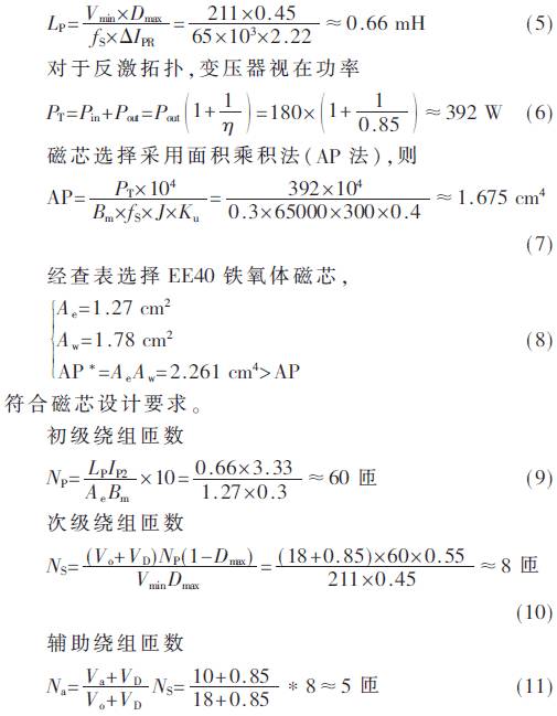
1.1.2 High-Frequency Transformer Design
The high-frequency transformer design is the most critical part of the switch power supply design, as the performance of the transformer directly affects the operational stability and performance of the switch power supply. Formulas (1) to (11) provide the calculation process for parameters in high-frequency transformer design. Here, Bm is the maximum change in flux density, J is the current density, Ku is the window coefficient, Vo is the output voltage, VD is the rectifier diode voltage drop, and Va is the auxiliary winding output voltage.
The minimum primary input voltage
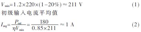
The peak primary current
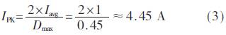
In CCM mode, the minimum value of trapezoidal pulse width current is IP1 and the maximum value is IP2. If IP2=3IP1, and IP1+IP2=IPK, then:

The minimum primary winding inductance
Based on formulas (1) to (11), calculate the high-frequency transformer parameters and use Saber software for modeling analysis, yielding the results shown in Figure 3. Here, the transformer winding structure has the primary winding wound NP/2 turns in both the innermost and outermost layers, while the secondary winding and auxiliary winding are wound in the middle layer to reduce transformer leakage inductance.
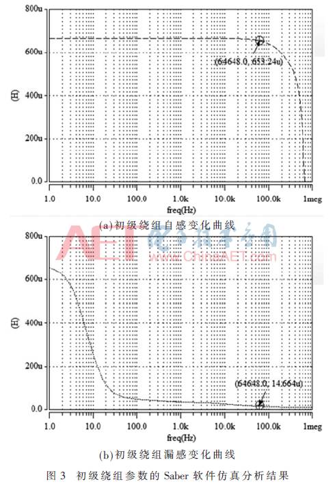
Figure 3 shows that at a working frequency of 65 kHz, the transformer’s self-inductance matches the calculated results; the transformer leakage inductance is small, reducing the voltage stress on the switching device, which meets design requirements.
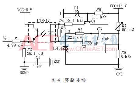
1.1.3 Loop Compensation
Loop compensation uses the TL431 and linear optocoupler LTV817 to form an external error amplifier, using the output error of the switch power supply as a feedback signal to adjust the PWM duty cycle output by UC3843, achieving stable output voltage of the switch power supply. Figure 4 shows the loop compensation formed by TL431 and LTV817. Here, R5, C2, and C3 form a second-order link with integration, ensuring the stability and speed of the system’s response.
1.2 Digital Control Unit Circuit Design
The AVR microcontroller’s digital control unit uses PWM modulation technology for unified management of the battery charging and discharging processes. The digital control unit mainly includes three parts: data acquisition and processing unit, battery charging and discharging control and reverse connection protection circuit, and MOSFET gate drive unit.
1.2.1 Data Acquisition and Processing Unit
The terminal voltage of the 12 V battery varies between 10.5 V and 14.0 V during operation, and the microcontroller’s AD conversion reference voltage is 5 V. Therefore, it is necessary to linearly condition the sampling signal. This design uses resistors with values of 400 kΩ and 100 kΩ, with an accuracy of 1%, for voltage division sampling, with a division factor k=0.2.
The charging and discharging current of the battery is obtained using a Hall sensor. Since the sensor’s output has a 2.5 V DC offset, a differential circuit using LM358 is constructed to eliminate the offset voltage and reduce the conversion and calculation time of the microcontroller, obtaining the actual current conversion voltage for AD sampling.
Due to the presence of circuit noise and external interference, various noises mix into the AD sampling signal. To improve the signal-to-noise ratio of the sampling signal, this paper designs a second-order active low-pass filter using the Butterworth design method with a passband cutoff frequency of 100 Hz, a stopband cutoff frequency of 500 Hz, and an output gain of 1.
1.2.2 Battery Charging and Discharging Control and Reverse Connection Protection Circuit
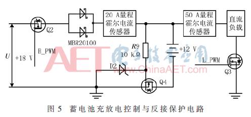
The system uses PWM to achieve unified management of the battery charging and discharging processes. According to the voltage-current characteristics of the MOSFET, it can be seen that in the saturation region of the MOSFET, when VGS is fixed, the change in VDS has little effect on IDS, exhibiting constant current source characteristics. Therefore, by adaptively adjusting the gate-source voltage of the MOSFET using a digital PI controller, a set constant current output can be achieved, realizing multi-stage constant voltage current-limiting charging management. During the discharging process, the battery’s terminal voltage gradually decreases from 13.1 V to the working cutoff voltage of 10.5 V, causing instability in the battery’s output. Therefore, PWM modulation is used to supply power to the DC load, ensuring stable output from the battery.
To prevent the battery from discharging back into the switch power supply circuit after the AC power source is disconnected, a Schottky diode MBR20100 is used in series in the loop to prevent reverse discharge from the battery due to the diode’s unidirectional conduction characteristic. Additionally, to prevent damage to circuit board components due to reverse connection when the battery is connected, a MOSFET reverse connection protection circuit is designed. A resistor R9 and a Zener diode D2 provide the gate-source voltage for the MOSFET. When the battery is reverse-connected, the gate-source voltage VGS=0, the MOSFET is turned off, and the charging circuit is disconnected. Figure 5 shows the design of the battery charging and discharging control and reverse connection protection circuit.
1.2.3 MOSFET Gate Drive
The MOSFET gate drive uses the IR4427 driver chip. This chip has independent in-phase dual PWM gate drive control channels, is TTL compatible, and can be directly controlled by the PWM output level of the microcontroller. In the design, two PWM signals are generated using the microcontroller’s timer 0 and timer 1, respectively connected to the PWM input terminals of the IR4427, thus generating PWM signals directly used to drive the MOSFET in the charging and discharging control loop.
2 System Software Design
2.1 Battery Management Program Design
The software design uses μC/OS-II ported to the AVR microcontroller as the program running platform, employing multitasking management to achieve efficient and reliable control of the battery charging and discharging processes.
μC/OS-II is a preemptive real-time operating system, where the CPU always runs the highest priority ready task. Therefore, task priority needs to be reasonably allocated based on the real-time nature and importance of the tasks during task assignment.
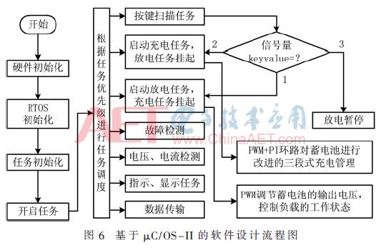
Porting μC/OS-II to the AVR microcontroller requires modifications to the code related to the processor and application. Processor-related modifications include macro definitions in the header file OS_CPU.H for the processor’s word length, data types, interrupts, and stack growth direction; four subroutines in the assembly file OS_CPU_A.ASM: OSStartHighRdy (to keep the task pointer always pointing to the highest priority task control block OS-TCB), OSCtxSw (for normal task switching), OSInitCtxSw (for interrupt-level task switching), and OSTickISR (for clock tick interrupts); and the stack initialization function OStaskStkInit() in the C file OS_CPU_C.C, which simulates an interrupt in the task stack. The application-related code file INCLUDES.H is used for file inclusion in the program, simplifying header file writing and enhancing code portability; OS_CFG.H contains macro definitions for starting configurations of operating system functions. Figure 6 shows the software design flowchart based on the μC/OS-II operating system platform.
2.2 Battery Lifespan Assessment Prediction Algorithm Design
This design employs lifespan prediction algorithms to assess the performance and lifespan of the battery. The steps for algorithm design are as follows:
(1) Using the battery discharge curve as the analysis standard, the point at which the battery voltage drops to 12 V is taken as the starting point for recording analysis data;
(2) A sampling frequency of 100 Hz is used, with sliding window mean filtering applied to preprocess the sampling sequence;
(3) Sampling values are recorded once per second, repeated 50 times, and the average of the obtained sampling values is denoted as Yi;
(4) Step (3) is repeated 8 times to obtain the output sequence Y={Yi}, input sequence X={Xi=i}, i=1,2,…,8;
(5) The least squares method is employed to perform high-order curve fitting on the partial discharge data to obtain the parameter identification results of each order coefficient.
The process of identifying the parameters of the fitted curve using least squares is as follows: first, determine the type of function; the chosen function type should be simple and easy to compute, while its geometric distribution should resemble that of the measured data. An n-th order polynomial is a commonly used and simple form. To reduce the computational complexity of the microcontroller, a second-order polynomial function type is chosen for fitting the measured data.
The mathematical expression for the fitting function type is:
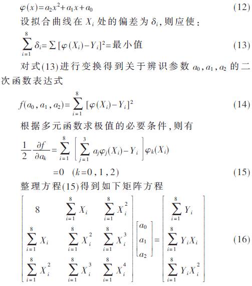
Solving the matrix equation yields the identified parameters a0, a1, and a2, which can then be used to assess and predict the battery’s performance and lifespan based on the identified parameter trends.
3 Experimental Testing and Case Analysis
To verify the system’s operational effectiveness, the following experiments were designed to validate the system’s functionality. The experiments used four 12V-12AH batteries working in parallel, with the discharge experiment using an inverter to convert the battery power to discharge two parallel 220 V–200 W special light bulbs.
3.1 Battery Charging and Discharging Experiments
The charging strategy employs multi-stage constant voltage current-limiting charging: trickle charging is used when the battery terminal voltage is below 10.5 V (the working cutoff voltage) with a small current of 1 A; when the terminal voltage is between 10.5 V and 13.5 V, constant current charging is initiated, with the maximum current set between 0.1 C and 0.25 C. In this design, the constant current charging current is set to 6 A, complying with the 8-hour charging rule; when the battery voltage is between 13.5 V and 14.0 V, a stepwise constant voltage current-limiting charging is applied, with the float charging current set to 0.01 C and taken as 0.5 A in this design.
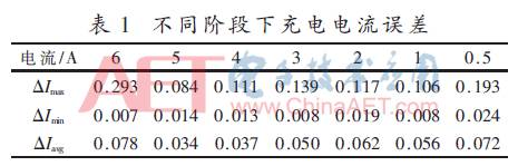
The battery discharge experiment uses PWM control, with the inverter converting the energy to AC output for the light bulbs. During the battery discharge process, the terminal voltage gradually decreases as the discharge progresses. When the voltage drops to the cutoff working voltage of 10.5 V, the PWM output remains low, disconnecting the load to prevent lifespan loss caused by excessive discharge. Figure 7 shows the battery charging and discharging curve under PWM control, with discharge current data taken from the sensor’s conversion output voltage, with a conversion accuracy of 40 mV/A, used to evaluate the control effectiveness of this battery management system; Table 1 presents the control errors of charging current at different charging stages to assess the accuracy and effectiveness of the battery charging phase division under digital PI control.
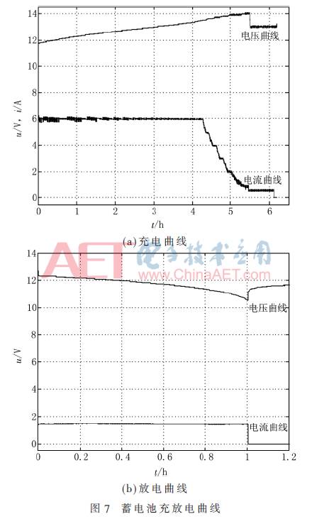
From Figure 7, it can be seen that under digital PI control, the multi-stage constant voltage current-limiting charging method is effectively implemented, and PWM-controlled discharging exhibits good constant current characteristics.
From Table 1, it can be seen that the maximum error ΔImax<0.3 A, the minimum error ΔImin<0.2 A, and the average error ΔIavg<0.1 A at different charging stages, indicating that the PI controller achieves high control accuracy in the battery charging process.
3.2 Battery Lifespan Prediction
To allow users to promptly understand the battery’s performance and remaining lifespan during use, the lifespan prediction assessment algorithm is employed to obtain the first-order and second-order coefficients of the battery’s partial discharge fitting curve, assessing the battery’s performance and remaining lifespan. Table 2 presents the fitting results of the partial discharge curve of the battery after several discharges.
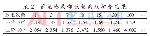
According to Table 2, as the number of battery discharges increases, the absolute value of the first-order coefficient of the fitting curve increases, while the second-order coefficient shows no obvious pattern. Thus, it is concluded that effective assessment and prediction of the battery’s performance and lifespan can be achieved through the calculation of the first-order coefficient of the partial discharge fitting curve starting from 12 V, guiding users in the use and maintenance of the battery.
4 Conclusion
This system effectively manages the 12 V on-board battery through the comprehensive application of μC/OS-II real-time multitasking management, flyback switch power supply technology, digital PI controllers, and PWM modulation techniques. The system prevents undercharging, overcharging, and excessive discharge, includes fault detection and alarm functions, and provides performance and lifespan prediction analysis for the battery; while improving charging efficiency and ensuring power supply duration, it effectively guarantees and enhances the lifespan of the on-board battery. Additionally, this paper proposes a method for assessing the battery’s lifespan and performance by fitting the partial discharge curve using least squares to obtain the first-order coefficient, providing reference suggestions for users regarding battery maintenance and management. Furthermore, to avoid misjudgment of assessment results due to distortion of fitting results, the system also employs statistical methods to identify misjudgments by counting the complete charging and discharging cycles of the battery.
Currently, this system is mainly applied to 12 V on-board battery management and is in the trial phase. Further research will design more reliable assessment algorithms, integrating machine learning and artificial intelligence concepts to make the system more intelligent, providing more comprehensive and reliable maintenance and management functions for the battery. This system also has certain application prospects for managing batteries in 12 V photovoltaic systems, allowing modification of the driving program and peripheral hardware circuits according to design requirements for effective management of photovoltaic system batteries.
References
[1] Tang Dingde, Zhou Qing. Intelligent control system for photovoltaic rapid charging of electric bicycles[J]. Power Supply Technology, 2016, 40(4): 781-782.
[2] Munshi A Q, Sayeed K A, Mishu M. Intelligent 3-stage MPPT lead acid battery auto charger[C]. Renewable Energy Research and Applications (ICRERA), 2013 International Conference on. IEEE, 2013: 913-917.
[3] Wu Kai, Cheng Qiming, Li Ming, et al. Fast charging and discharging method for electric vehicles with V2G function[J]. Power Automation Equipment, 2014, 34(2): 30-34.
[4] Levente S. Contribution to charging of battery with pulses[C]. Design and Technology in Electronic Packaging (SIITME), 2015 IEEE 21st International Symposium for. IEEE, 2015: 165-168.
[5] Huang Huixiong, Yuan Lihui, Luo An. Research on fast charging system for electric vehicle batteries based on μC/OS-II[J]. Computer Engineering and Design, 2009(16): 3741-3744.
[6] Xu C, Wang S. Effects of mix-mode noise emissions on the design method of planar EMI filter[C]. 2013 IEEE 8th Conference on Industrial Electronics and Applications (ICIEA). IEEE, 2013: 696-699.
[7] Chern G T, Shieh J J, Chao C H, et al. Reducing differential-mode EMI and low-frequency common-mode voltage in switching-mode power converters[C]. Electrical Machines and Systems (ICEMS), 2011 International Conference on. IEEE, 2011: 1-5.
[8] Meslem N, Le V T H, Labarre C, et al. Set-membership methods applied to identify high-frequency elements of EMI filters[J]. Control Engineering Practice, 2014, 29: 13-22.
[9] Jiang Xinyi, Shi Yandong. Research on feedback network of single-ended flyback switch power supply[J]. Power Supply Technology, 2015(11): 2484-2486.
[10] Zhang Zhengguo, Wang Minhua, Qu Fei, et al. Application of TL431 in the feedback loop of switch power supply[J]. Information Technology, 2014, 38(2): 73-76.
[11] Shieh C S. Fuzzy PWM based on Genetic Algorithm for battery charging[J]. Applied Soft Computing, 2014, 21: 607-616.
[12] Caspar M, Hohmann S. Optimal cell balancing with model-based cascade control by duty cycle adaptation[J]. IFAC Proceedings Volumes, 2014, 47(3): 10311-10318.
[13] Wang Yongrui, Han Bing, Zhang Zhonghua, et al. A fast prediction method for the lifespan of valve-regulated sealed lead-acid batteries[J]. Metrology Technology, 2015(3): 22-24.
[14] Dang Wusong, Fan Hanbai, Hu Yang. Design and research of intelligent fast charger based on ATmega16 microcontroller[J]. Power Supply Technology, 2015, 39(3): 550-552.
[15] Zhang Lei, Zhu Qian, Yang Xueguang, et al. Research on the relationship between VRLA cycle life and float charging current[J]. Power Supply Technology, 2014, 38(1): 70-72.