Click the blue text to follow us
1. Structure and Signal Pins of 80C51 Microcontroller
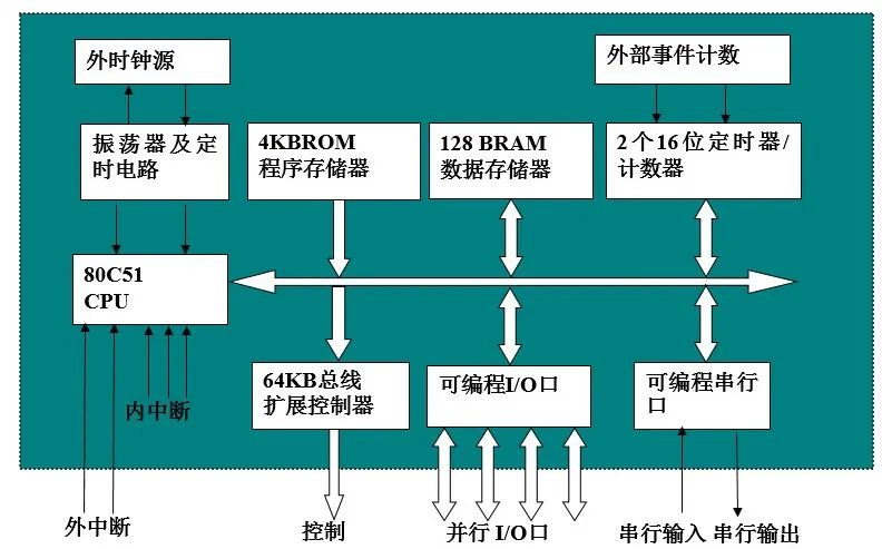
Figure 1: Block Diagram of 80C51 Microcontroller System Structure
1. Basic Components of 80C51 Microcontroller
-
Central Processing Unit (CPU): 8-bit, operational and control functions
-
Internal RAM: A total of 256 RAM units, with the first 128 units for user data and the last 128 units occupied by special registers.
-
Internal ROM: 4KB mask ROM for storing programs, raw data, and tables.
-
Timer/Counters: Two 16-bit timer/counters for timing or counting functions.
-
Parallel I/O Ports: Four 8-bit I/O ports P0, P1, P2, P3.
-
Serial Port: One full-duplex serial port.
-
Interrupt Control System: Five interrupt sources (2 external interrupts, 2 timer/counter interrupts, 1 serial interrupt)
-
Clock Circuit: Generates clock pulse sequences, allowing crystal frequencies of 6MHz and 12MHz.
-
An 8-bit CPU;
-
4KByte program memory;
-
128Byte data memory;
-
Two 16-bit timer/counters;
-
64KByte extended bus control circuit;
-
Four 8-bit parallel I/O ports;
-
One programmable serial interface;
-
Five interrupt sources, including two priority nested interrupts;
-
Internal oscillator.
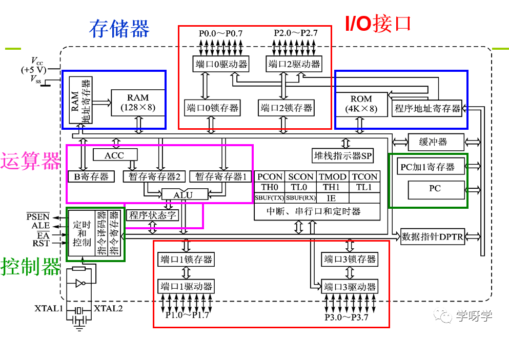
Figure 2: Internal Logic Structure of 80C51 Microcontroller Chip
3. The Entire Process of Microcontroller Program Execution
The execution of the program in the microcontroller is carried out under the control of the control circuit.
First, instructions are read from the program memory and sent to the instruction register for storage;
Then, the instructions are sent to the instruction decoder for decoding, and the decoding results are sent to the timing control circuit, which generates various timing and control signals;
These are then sent to various components of the system to control the corresponding operations.
This is the entire process of executing a single instruction, and executing a program involves repeating this process continuously.
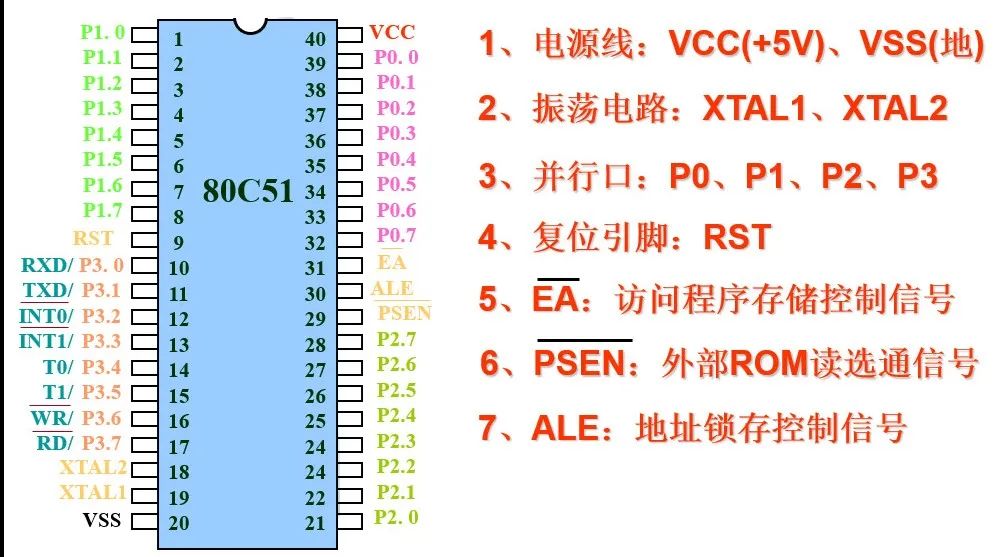
4. Pin Arrangement and Logic Symbols of 80C51 Microcontroller
5. Internal Memory of 80C51 Microcontroller
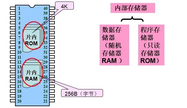
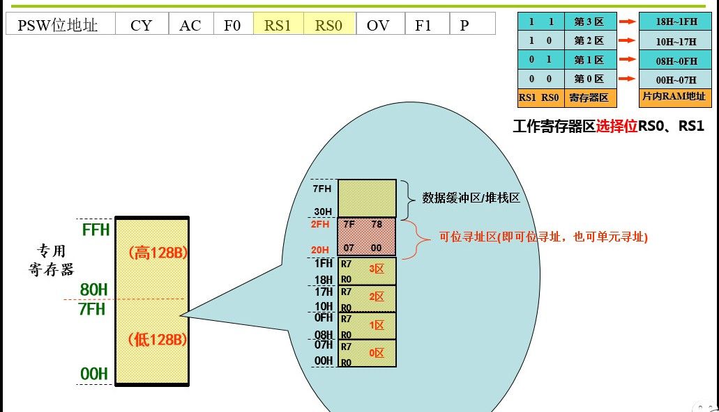
Figure 3: Internal Data Memory
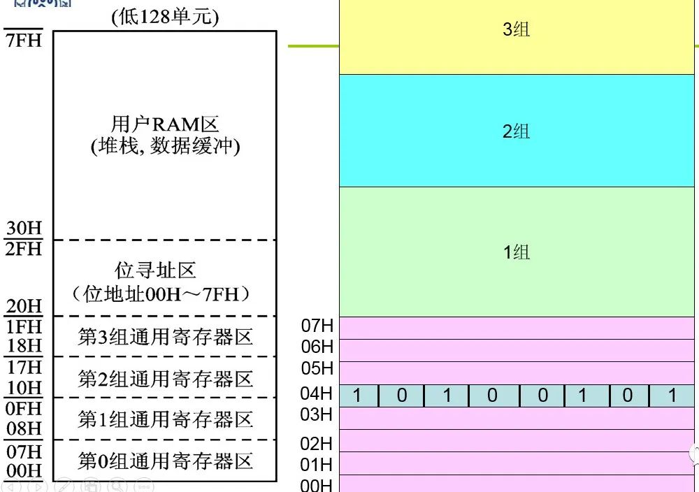
Figure 4: Configuration Diagram of 80C51 Internal Data Memory
6. Access Method of Low 128B