 In the previous experiment, we learned about the principle of the running light—multiple LEDs lighting up and turning off in sequence. In this experiment, we will learn how to implement a breathing light using Arduino. Unlike the running light, the breathing light achieves a “breathing” display effect by gradually adjusting the brightness of the LED.1. Experiment Materials 1. Arduino development board ×1 2. RGB LED ×1 3. 220Ω resistors ×3
4. Breadboard ×1
5. Dupont wires (male to male) × several
6. USB data cable ×1
2. Experiment Principle2.1 RGB LED According to the theory of primary colors, the human eye perceives most colors in nature through the combination of red (R), green (G), and blue (B) light. Based on this principle, RGB LEDs are designed by combining LEDs that emit red, green, and blue light of different wavelengths. The RGB LED produces different colors of light by adjusting the intensity of the red, green, and blue monochromatic lights.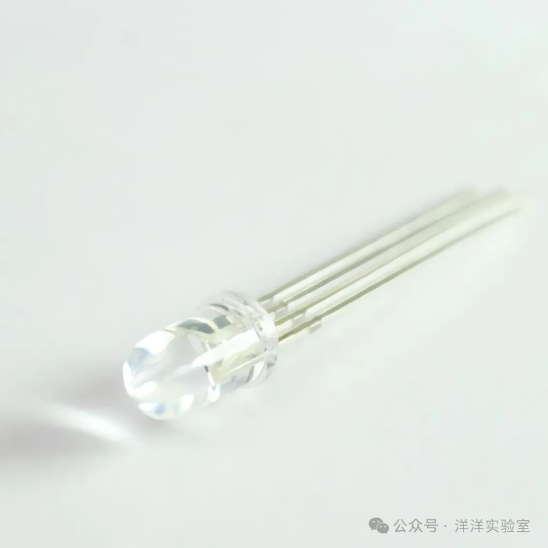 The RGB LED has 4 pins, including 1 common pin and 3 color control pins. RGB LEDs can be classified into common anode and common cathode types. If the anodes (positive terminals) of the three LEDs are connected to a common pin, and the cathodes (negative terminals) are connected independently, it is a common anode; if the cathodes are connected together, it is a common cathode.2.2 PWM Principle The brightness of an LED is proportional to the current flowing through it. Directly adjusting the current may affect the effect, so a common method to adjust LED brightness is to use PWM signals. PWM stands for Pulse Width Modulation. PWM signals are periodic square waves composed of alternating high (ON) and low (OFF) levels. By adjusting the duty cycle, the time the load is powered can be changed.
In addition to the duty cycle, another important parameter of PWM signals is frequency. The common frequency ranges for PWM are as follows:
1) LED dimming: 100Hz ~ 1kHz (to avoid visible flicker)
2) Motor control: 1kHz ~ 20kHz (to reduce noise)
3) Switching power supplies: 50kHz ~ 1MHz (to improve efficiency)
2.3 Breathing Light Principle As mentioned earlier, the breathing light achieves a “breathing” display effect by gradually adjusting the brightness of the LED. Here, brightness is defined as a number from 0% to 100%. The brightness adjustment of the breathing light consists of two processes: fading in (0% -> 100%) and fading out (100% -> 0%), with each adjustment being 5% brightness. The essence of brightness adjustment is to change the duty cycle of the PWM signal. Arduino outputs the PWM signal through analogWrite(pin, value), where the value ranges from 0 to 255, and the duty cycle is the ratio of value to 255.3. Experiment Content First, connect the three color ports of the RGB LED through 220Ω resistors to the digital pins 9 to 11 of the Arduino. The common cathode of the RGB LED is connected to the GND bus of the breadboard, and then connected to the GND pin of the Arduino using Dupont wires.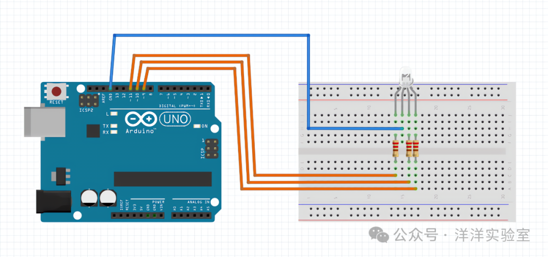 Write the code in the Arduino IDE, and here is the reference code.
int rPin = 11;int gPin = 10;int bPin = 9;int color[] = {255, 255, 255}; // Color arrayint direction = 0; // Brightness adjustment directionfloat brightness = 0; // Initial brightnessvoid setup() { // analogWrite() does not require initialization}void loop() { if (direction == 0) { brightness = brightness + 0.05; } else { brightness = brightness - 0.05; } if (brightness >= 1) { direction = 1; } else if (brightness <= 0) { direction = 0; } analogWrite(rPin, int(brightness * color[0])); analogWrite(gPin, int(brightness * color[1])); analogWrite(bPin, int(brightness * color[2])); delay(100);}Connect the Arduino to the computer using a USB cable, select the correct board and port.Upload the code and observe the display effect of the RGB LED.