IntroductionIn PLC learning, many people fall into the trap of “piling up instructions”—memorizing the usage of timers and counters but unable to create a stable quiz buzzer. In fact, the quiz buzzer seems simple but hides the core logic of industrial control:signal priority judgment, interlocking to prevent conflicts, and state reset management. Today, we will take the Siemens S7-200 SMART as an example to break down the progression from “audible” to “industrial-grade stability”!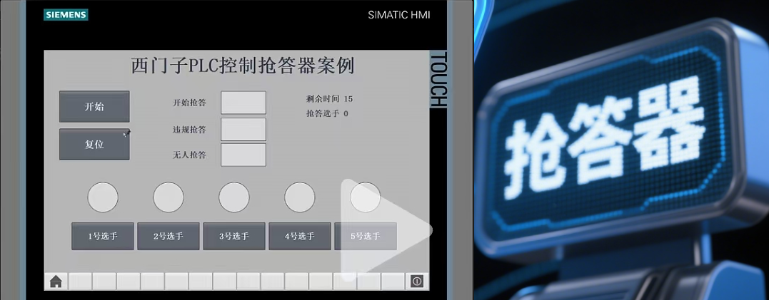
1. Analyze Control Requirements
According to the control requirements, the system’s start and stop is a self-locking control; the buttons used for the four quiz stations are pressed and released, but the corresponding indicator lights cannot go out, so the indicator lights of the four quiz stations are also self-locking control; the first quiz station to be pressed will light up its indicator, and the other quiz stations will not work when their buttons are pressed, so there is interlocking control among the four quiz stations; the anti-cheating function requires new knowledge, which will be explained in the program design.
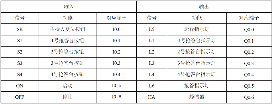
2. Allocate Inputs and Outputs
3. Electrical Schematic of the Quiz Buzzer Control
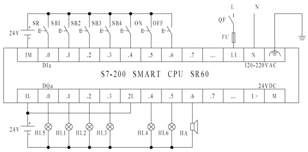
4. Perform Wiring Installation and Testing
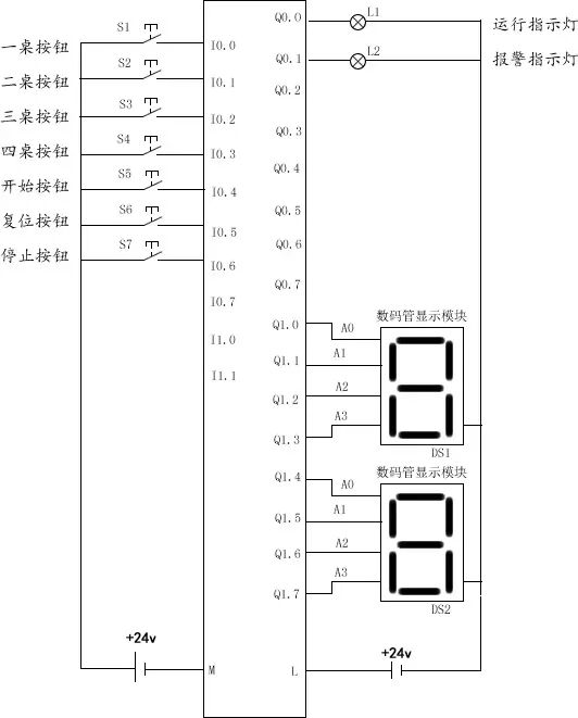
5. Write Ladder Diagram Program
First, create a symbol table in the programming software based on the I/O terminal allocation table.
(1) System Start and Stop
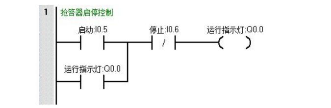
When the host presses the start button, the system running indicator lights up, and the system enters the running state. When the host presses the stop button, the system stops, and the running indicator goes out. The start-stop control program can be designed as shown in the diagram.
(2) Quiz Station Control
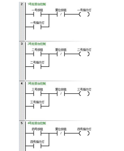
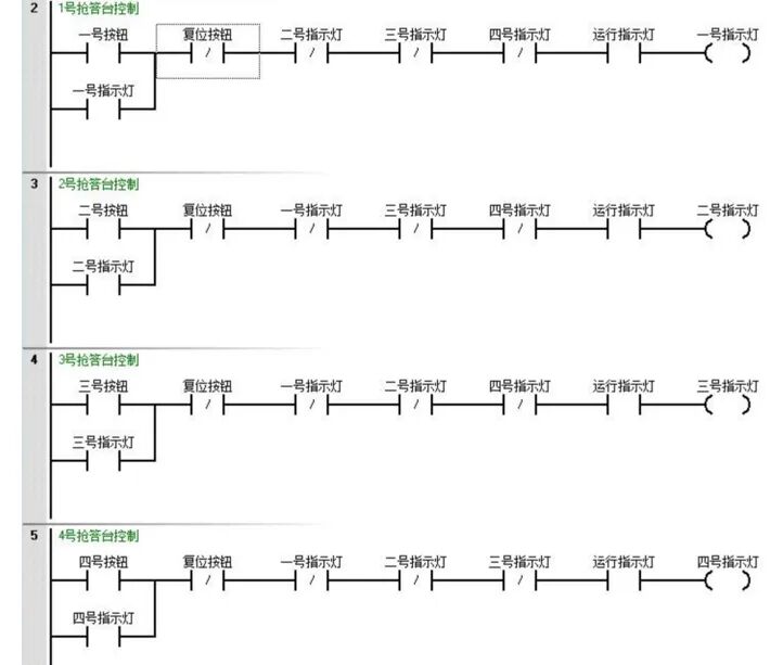
When a contestant presses the quiz button, the corresponding quiz station indicator remains lit. When the host presses the reset button, the contestant’s station indicator goes out. The quiz buzzer must have a buzzer function, meaning that the indicator of the quiz station that pressed the button first lights up, while the indicators of other quiz stations do not light up when their buttons are pressed, thus having interlocking functionality. At the same time, we also need to ensure that all four quiz stations are controlled by the system’s start and stop. The control program can be designed as shown in the diagram.
(4) Buzzer Control
No matter which quiz station presses the quiz button, the indicator lights up, and at the same time, the buzzer must emit a quiz sound, lasting 0.5 seconds. A timer needs to be added to time the sound, and when the time is up, the buzzer should be disconnected. Therefore, the start signal for the buzzer should be the quiz button of each quiz station, and the stop signal should be the timer. Additionally, since the quiz button cannot be pressed continuously for 0.5 seconds, self-locking must be added. Based on the control function, we design the control program as shown in the diagram.
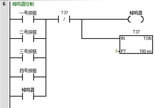
We will observe the control function through programming, downloading, and debugging. We will find that the above program has a problem: whenever we press a button once, the buzzer will sound for 0.5 seconds, which means the buzzer is uncontrolled. During the answering process, pressing the button will produce sound, affecting the answering. Therefore, the above program needs further improvement. When a quiz station presses the button and the quiz is completed, the buzzer sounds, and the timer should not lose power. We can directly use the indicators on each quiz station to control it, making the program more scientific. Adding the system’s start-stop control, the improved program is shown in the diagram.
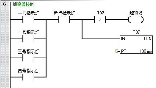
(5) Quiz Indicator Control
The quiz indicator is in the running state. When the system is in the quiz state, the quiz indicator lights up. If someone has already completed the quiz, the indicator goes out. Therefore, the quiz indicator and the indicators on each quiz station have an opposite relationship: if all quiz station indicators are not powered, the quiz indicator is powered. As long as one quiz station indicator is powered, the quiz indicator cannot be powered, so the designed program is shown in the diagram.

(6) Anti-Cheating Control
Following the above steps, the quiz buzzer control program is basically complete, but are there any issues with the program? For example, if a contestant keeps pressing the button, maintaining a continuous connection, what will happen? The contestant who keeps pressing the button will successfully buzz in. How can we solve this? This is where the edge detection instruction comes into play, as it detects the moment the input changes from open to closed or from closed to open. We can use the positive edge instruction to solve the situation where a contestant maliciously buzzes in by pressing the button early, as shown in the program.
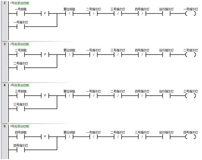
(7) Complete Control Program
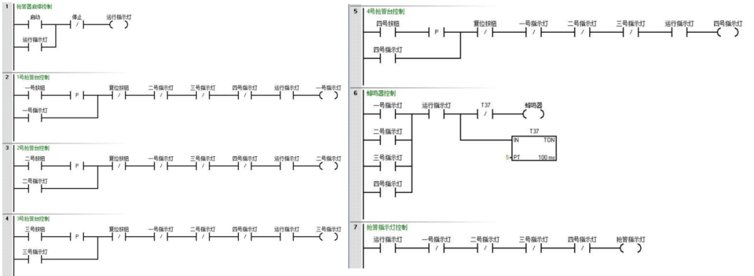
6. Transmission Debugging
(1) Compile Program
Click the “Compile” button in the toolbar to compile the user program and check for syntax errors.
(2) Save Project
Click the “Save Project” button in the toolbar to save the user program.
(3) Download Project
Click the “Download” button in the toolbar to download the user program.
(4) Debugging
After the program download is complete, debug according to the table.
|
Operation Steps |
Operation Content |
Observation Content |
Observation Result |
Thought Content |
|
1 |
Click the “Program Status” monitoring button in the toolbar to monitor the program. |
PLC indicator status and programming interface status |
||
|
2 |
Click the “RUN” button to run the PLC. |
“STOP” and “RUN” indicator status |
||
|
3 |
Write and download the start-stop control program, press the start button ON |
I/O indicator status, running indicator, quiz indicator, quiz station indicators, buzzer, etc. |
Can the program be optimized, are there any missing functions? |
|
|
4 |
Press the stop button OFF |
|||
|
5 |
Write and download the quiz station control program, press the start button ON |
|||
|
6 |
Randomly press the buttons of the quiz stations, then press the buttons of other quiz stations, and press the reset button |
|||
|
7 |
Repeat the above operations |
|||
|
8 |
Press the stop button OFF |
|||
|
9 |
Write and download the buzzer control program, press the start button ON |
|||
|
10 |
Randomly press the buttons of the quiz stations, then press the buttons of other quiz stations, and press the reset button |
|||
|
11 |
Randomly select a quiz station button, press it before resetting, then press the reset button |
|||
|
12 |
Press the stop button OFF |
|||
|
13 |
Write and download the control program with edge detection instructions, press the start button ON |
|||
|
14 |
Randomly press the buttons of the quiz stations, then press the buttons of other quiz stations, and press the reset button |
|||
|
15 |
Randomly select a quiz station button, press it before resetting, then press the reset button |
|||
|
16 |
Press the stop button OFF |
|||
|
17 |
Stop the CPU module operation through the programming software. |
“STOP” and “RUN” indicator status |
||
|
After debugging, turn off the power switch QF and organize the equipment and materials. |
Conclusion: This small project covers the three major underlying logics of industrial control
Interlocking thinking: just like the machine tool’s “emergency stop takes priority over start”, using output to control input to avoid equipment conflicts;
State management: from “waiting to trigger to lock → reset” state transition, corresponding to the production line’s “standby → running → fault → shutdown”;
Anti-interference design: button debounce, timeout detection, essentially a reflection of the “electromagnetic interference” signal loss in the industrial field.
Learning to use PLC to make a quiz buzzer is not just to create a toy, but to master the ability to “turn chaotic signals into orderly actions”—this is the core of programming, not rote memorization of instructions.
Previous Recommendations
Stop chewing on books! 11 methods for Mitsubishi PLC dual-button control of motor start and stop from beginner to expert, just copy for beginners!
Step-by-step guide to PLC device debugging, master these 7 golden rules to transform from a “rookie” to a “pro”
No more asking for help with sensor wiring: comprehensive diagrams for two, three, four, and five wires, say goodbye to burning modules
No more confusion in electrical design! Understanding these 50 classic diagrams can save you 3 years of detours!
Classic PLC programming examples, dual constant pressure water supply system from design to debugging: includes PLC program + wiring diagram + PID parameter table, learn it and you can use it!
Collectible! 100 dynamic images to instantly understand PLC and sensor principles, engineer’s private stash revealed
Master these electrical control knowledge to be worthy of the title “master” (includes high-definition wiring diagrams)
Mitsubishi Works2 programming software beginner’s guide, easy to get started even with zero foundation!
Beginner’s guide to learning Siemens Smart, from wiring to writing a complete program!
Latest popular software collection
Latest industrial control technology article summary