
Someone is using STM32F4 series chips to develop products and is using the DAC module. They discovered a strange phenomenon while using the DAC. They found that every time they used HAL_DAC_SetValue () to modify the output data, they also had to call HAL_DAC_Start () to output the corresponding DAC result. The code needs to be organized as follows:
HAL_DAC_SetValue(&hdac,DAC_CHANNEL_2, DAC_ALIGN_12B_R,adc_buf_12[sample_pos] );//Set value for DAC
HAL_DAC_Start(&hdac, DAC_CHANNEL_2);//Start DAC
According to their understanding, under normal usage, it should not be necessary to call HAL_DAC_Start to start the DAC module first, and then call HAL_DAC_SetValue () to produce the corresponding output. If necessary, call HAL_DAC_Stop () to disable the DAC. Why do they have to call the HAL_DAC_Start () function every time they modify the data?
It does sound a bit strange!
I quickly verified this using the STM32F407 development board. I configured it using CubeMx and used the same DAC channel as the user. The configuration is as follows:
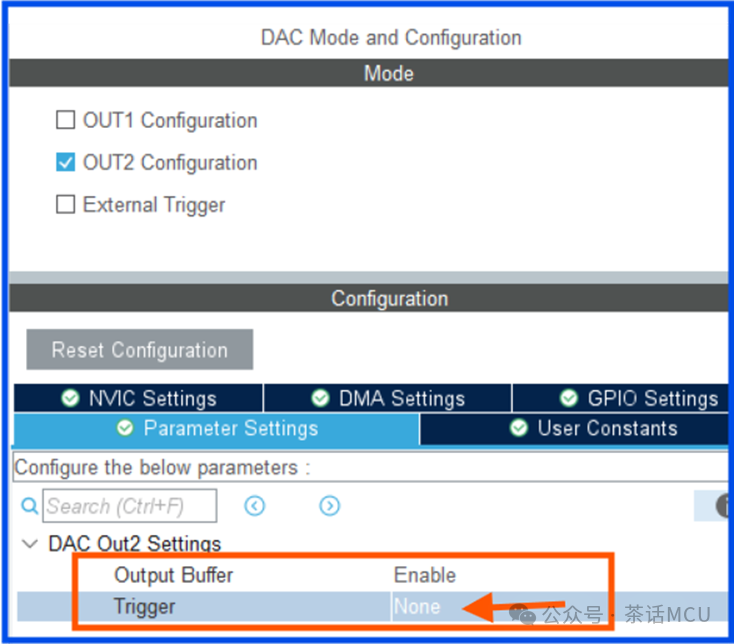
After creating the project, I added the following test code. The functionality of the code is very simple, which is to use the DAC to periodically output a sawtooth wave.
HAL_DAC_Start(&hdac, DAC_CHANNEL_2);
while (1)
{
for(uint8_t i=5;i>0;i–)
{
USR_DELAY;
HAL_DAC_SetValue(&hdac, DAC_CHANNEL_2, DAC_ALIGN_12B_R,( i-1) * 1000 );
}
}
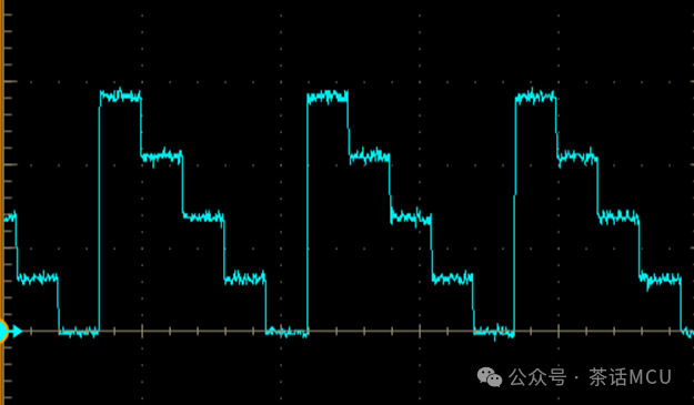
Based on the above configuration and test code, the test results indicate that every time the HAL_DAC_SetValue() function is called, it takes effect immediately, and there is no need to call the HAL_DAC_Start() function after modifying the new value. The output also meets the design expectations, as seen in the oscilloscope screenshot below.
What could be the reason?
Further investigation revealed that their DAC configuration was slightly different from mine. I did not enable the trigger function of the DAC, while they did enable it, choosing the software trigger method. Specifically, they modified the relevant control bits through software to generate trigger events.
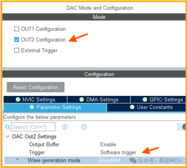
I adopted their configuration and my previous test code, and the sawtooth wave disappeared! The output was locked at a certain level. When I changed the code to match theirs, that is, when the code was modified to the following form, the sawtooth wave was output normally again.
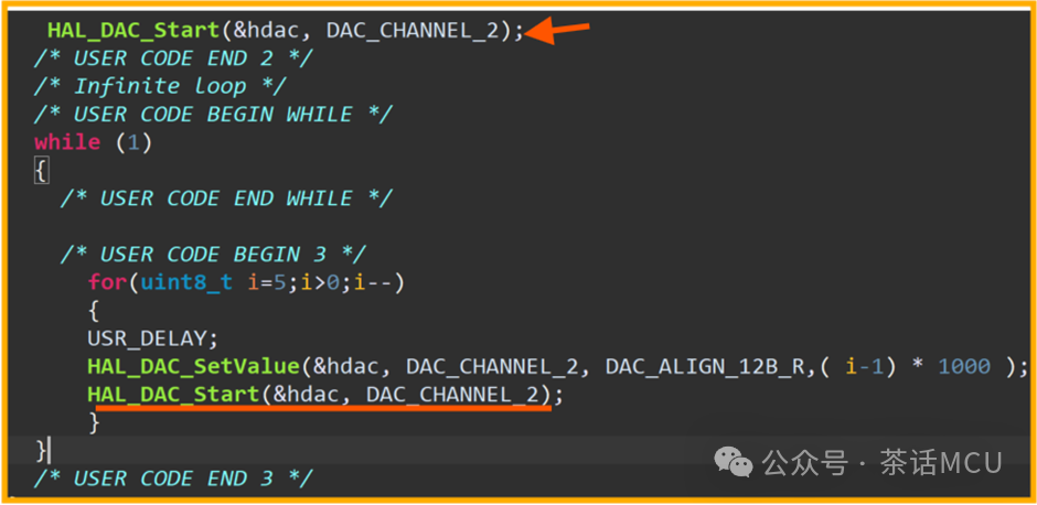
At first glance, when the software trigger method of the DAC is enabled, every time a new value is modified, the DAC_Start() function must be called. According to the output characteristics of the DAC, the new value takes effect only when a trigger event is generated. Why is it necessary to restart the DAC channel every time?
When using the DAC, we mainly deal with two registers, namely the data holding register and the data output register of the DAC, which are DHRx and DORx registers, where x represents the channel number.
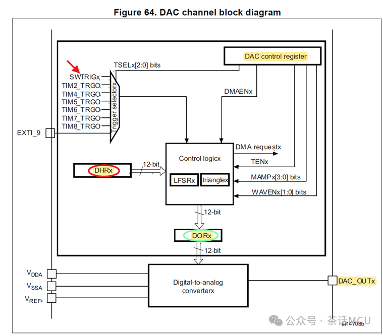
Among them, our application can only operate on the DHRx register, while the actual output voltage corresponds to the content of the DORx register, which cannot be directly written by the application.
All data must be written to DAC_DHRx, and the data from DHRx to DORx registers also has a transfer process. The data transfer mechanism is as follows:
- No trigger (TENx=0) :
- After you write to DAC_DHRx, the data will automatically transfer to DAC_DORx after 1 APB1 clock cycle, and the DAC output will be updated immediately..
- This is the behavior when Trigger=None, writing data= immediate output.
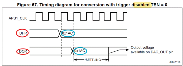
- With trigger (TENx=1) :
- After you write to DAC_DHRx, the data will only transfer to DAC_DORx when the trigger event occurs.
- After the trigger event occurs, the data will be output after 3 APB1 clock cycles.
- This is the behavior when Trigger=Timer/Software/External, writing data + trigger = output.
In this case, even when using the DAC trigger output function, to make the new value effective, it only requires a trigger event, and there is no need to repeatedly call the DAC channel start function?
Let’s take a look at the HAL_DAC_Start() API function.
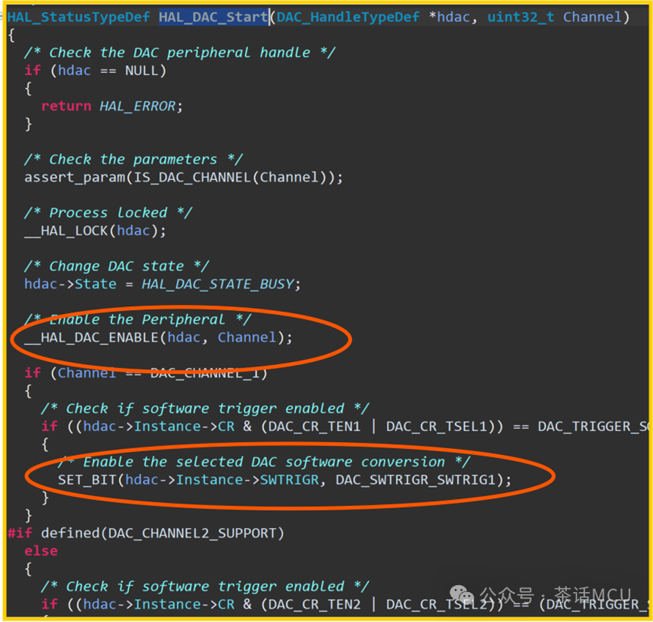
It turns out that this start function mainly does two things: one is to start the DAC related channel, and the other is to check if the software trigger conversion is enabled, then operate the relevant register control bits to generate trigger events. No wonder calling this start function is effective every time a new value is modified.
Is it necessary to operate this way? Obviously not, as when I replaced the call to the DAC start function in the code directly with the code that generates trigger events through software, it also worked normally. See the code screenshot below:
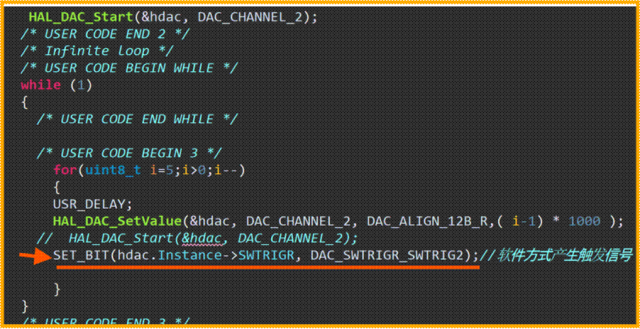
At this point, the situation is basically clear. First, there was a lack of understanding of the role of Trigger during configuration, and secondly, there was insufficient understanding of the functionality of the DAC start function itself, leading to some small confusions in application.
OK. That’s it for today’s sharing, let’s talk again next time.
*************************Previous topics reading links:1、 Example and reminders for multi-timer synchronized output applications2、 Precautions for jumping during STM32 IAP applications3、 Why does SPI’s DMA loop receive errors after enabling CRC?4、 HRTIM Dual channel DAC trigger application demonstration5、 Why can’t timer DMA burst transfer be achieved?