Without further ado, let’s watch the video. It’s a silent video, so feel free to guess what it is!
To be honest, I’ve been working on the development of ROS and Arduino collaboration, including rosserial, ros_arduino_bridge, StandardFirmata, and Modbus, but there are indeed few wireless solutions for ROS.
I previously considered using an Arduino Nano + OLED screen to create a display module for ROS peripherals, but I ran into two memory-heavy libraries—rosserial and the OLED library—which ultimately blew up my idea.
There are alternative solutions available, but I didn’t want to go that route.
When using rosserial, we only need to start the rosserial_python’s serial_node.py on the ROS system, and there isn’t much programming involved. The main advantage is using Arduino as a ROS node for development, which is quite comfortable!
For those interested in learning about rosserial and Arduino development, you can check out this link rosserial and Arduino.
*https://www.ncnynl.com/category/ros-arduino/
Subsequently, I achieved the effect using Arduino Mega. At that time, using an Arduino Mega or an Atmega2560 chip to drive a screen was indeed a bit extravagant. The code at that time was like this.
#include <ros.h> // Include ROS header file#include <std_msgs/String.h> // Include std_msgs String type data#include <Wire.h> // Include IIC protocol library#include <Adafruit_GFX.h> // Include font library#include <Adafruit_SSD1306.h> // Include SH1106 driver library, 1.3 inch OLED driven by SH1106#define OLED_RESET 4 // Define OLED as 4-pin modeAdafruit_SSD1306 display(OLED_RESET); // Instantiate OLED display functionalityros::NodeHandle nh; // Declare ROS handle/*************************************************************Function Name: oled_callback **Function Type: void **Function Function: Display the subscribed msg on the OLED screen when subscribed to the oled topic **Input Parameter: msg, the subscribed data **Output Parameter: None *************************************************************/void oled_callback(const std_msgs::String& msg){display.clearDisplay(); // Clear current screen contentdisplay.setTextSize(1); // Set display font sizedisplay.setTextColor(WHITE); // Set display font styledisplay.setCursor(0,0); // Set display font coordinatesdisplay.println(msg.data); // Set display font contentdisplay.display(); // Display} // Instantiate subscription, subscribe to the topic named oled, with message type std_msgs::String, and callback function oled_callbackros::Subscriber<std_msgs::String> sub("oled", &oled_callback); /*****************************Function Name: setup **Function Type: void **Function Function: Initialize related hardware **Input Parameter: None **Output Parameter: None *****************************/void setup(){display.begin(SSD1306_SWITCHCAPVCC, 0x3C); // Initialize OLED screen, IIC default address 0x3Cdisplay.display(); // Displaydelay(2000); // Delay 2000msdisplay.clearDisplay(); // Clear current screen contentdisplay.setTextSize(1); // Set display font sizedisplay.setTextColor(WHITE); // Set display font styledisplay.setCursor(0,0); // Set display font coordinatesdisplay.println("Hello, ROS!"); // Set display font contentdisplay.display(); // Displaydelay(2000); // Delay 2000msdisplay.clearDisplay(); // Clear current screen contentnh.initNode(); // Initialize node nh.subscribe(sub); // Subscribe} /*************************************Function Name: loop **Function Type: void **Function Function: Program execution content, loop execution **Input Parameter: None **Output Parameter: None *************************************/void loop(){nh.spinOnce(); // In Arduino's loop function, call nh.spinOnce(), so all ROS callback functions will be processeddelay(1); // Delay 1ms}You can find an Arduino Mega + OLED screen to test this out. The function of this code is to display “Hello ROS!” on the screen at startup, and then subscribe to a topic called oled, which is of type std_msgs/String, essentially a string, displaying the content of this string on the OLED screen.
And the only three steps we need to execute under ROS are:
roscore# Start ROS Masterrosrun rosserial_python serial_node.py# Start rosserialrostopic pub /oled std_msgs/String "Hello GYHome!"# Send a topic called oled, of type std_msgs/String, with content "Hello GYHome!">Actually, there isn’t much to it; it’s quite similar to the process of writing ROS nodes in C++ for subscriptions, and it’s even simpler! Just using an Arduino Mega to achieve this functionality is indeed extravagant.
The other day, I saw a blog post by Teacher Ruilai “Summary of Some Issues with ESP8266 and ROS Debugging”, which realized rosserial node communication through WiFi LAN. The video I just mentioned is about that!
This code is from the example code in rosserial_arduino—Esp8266HelloWorld. You can download it and try it yourself; please refer to the video for the operation steps. The code content is as follows:
/* * rosserial Publisher Example * Prints "hello world!" * This intends to connect to a Wifi Access Point * and a rosserial socket server. * You can launch the rosserial socket server with * roslaunch rosserial_server socket.launch * The default port is 11411 * */#include <ESP8266WiFi.h>#include <ros.h>#include <std_msgs/String.h> // Connect to the specified WiFiconst char* ssid = "Rugels.Dix";const char* password = "Qing990127";// Set the IP address of the computer where ROS Master is locatedIPAddress server(192,168,43,51);// rosserial tcp uses port 11411const uint16_t serverPort = 11411;ros::NodeHandle nh;// Make a chatter publisherstd_msgs::String str_msg;ros::Publisher chatter("chatter", &str_msg); // Be polite and say hellochar hello[13] = "hello world!";void setup(){ // Use ESP8266 serial to monitor the process Serial.begin(115200); Serial.println(); Serial.print("Connecting to "); Serial.println(ssid); // Connect the ESP8266 to the WiFi AP WiFi.begin(ssid, password); while (WiFi.status() != WL_CONNECTED) { delay(500); Serial.print("."); } Serial.println(""); Serial.println("WiFi connected"); Serial.println("IP address: "); Serial.println(WiFi.localIP()); // Set the connection to rosserial socket server nh.getHardware()->setConnection(server, serverPort); nh.initNode(); // Another way to get IP Serial.print("IP = "); Serial.println(nh.getHardware()->getLocalIP()); // Start to be polite nh.advertise(chatter);}void loop(){ if (nh.connected()) { Serial.println("Connected"); // Say hello str_msg.data = hello; chatter.publish( &str_msg ); } else { Serial.println("Not Connected"); } nh.spinOnce(); // Loop approximately at 1Hz delay(1000);}You need to modify the WiFi name and password, the IP of the computer running ROS, and the port 11411, which does not need to be changed.
My WiFi name is Rugels.Dix, the password is Qing990127, and the IP address of the computer is 192.168.43.51.
Then just run it, and the steps to run are as follows.
roscore# Start ROS Masterrosrun rosserial_python serial_node.py tcp# Start the serial_node node in the rosserial_python package, with the suffix parameter tcp indicating it's a tcp rosserialIf these two lines execute successfully, it will look like this.
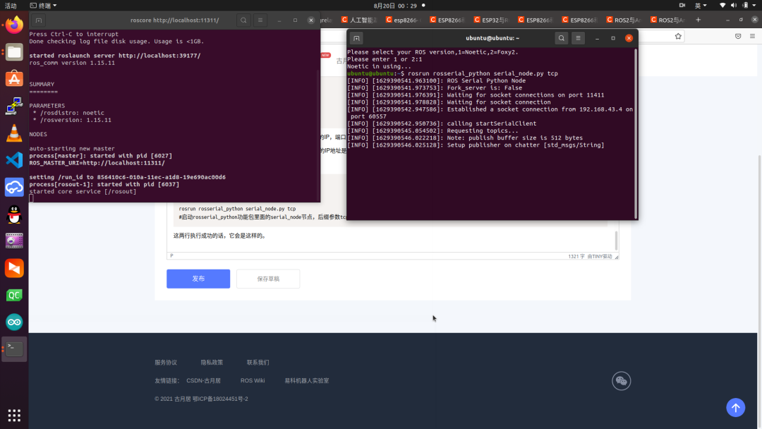
Then you can use rostopic and rqt to manipulate this data.
The official demo is quite simple; it only publishes a topic named chatter, of type std_msgs/String, with content “Hello World!”. I won’t go into detail here; you can interpret the code and operate it under ROS yourself, and you can easily see the data.
OK! Let’s continue. After this Russian verification, I found that using the ESP8266 was still promising. So I had another idea~
ESP8266 development board + OLED screen + PCA9685 servo driver board + rotary encoder interrupt + button operation + 5V 2A UPS, ultimately equals a super version of Double_Arm, and it even has teaching and button operation.
Then it turned out I was overthinking it!
ESP8266 is not compatible with the SH1106 OLED driver; I spent an afternoon researching the API I found on GitHub and still couldn’t figure it out. As for using the u8g2 library—don’t get me started on that library!
ESP8266 is not compatible with PCA9685; I found code that supports ESP8266 on GitHub, and the code is quite strange (so goodbye to you).
The rotary encoder interrupt and button, well, those two are fine~
And the 5V 2A UPS, no problem either.
So, let’s keep going~ After countless times of writing (copying) code, I finally came up with a version.
ESP8266 does not support SH1106 but supports SSD1306, so I got a 0.96-inch OLED screen (I still want to use the 1.3-inch one, mainly because it’s bigger! QAQ)
Let me share the code from this afternoon; it compiled successfully, but I don’t have a 0.96-inch OLED screen in hand, so I can only wait for the delivery to continue debugging! Let’s leave it at that for now~ Friends who have ESP8266 + 0.96-inch OLED screen can try it out first~
#include <ESP8266WiFi.h> #include <ros.h>#include <std_msgs/String.h> #include <Wire.h> // Include IIC protocol library#include <Adafruit_GFX.h> // Include font library#include <Adafruit_SSD1306.h> // Include SH1106 driver library, 1.3 inch OLED driven by SH1106#define OLED_RESET 4 // Define OLED as 4-pin modeconst char* ssid = "Rugels.Dix";const char* password = "Qing990127";IPAddress server(192,168,43,51);const uint16_t serverPort = 11411;ros::NodeHandle nh;Adafruit_SSD1306 display(OLED_RESET); // Instantiate OLED display functionalityvoid oled_callback(const std_msgs::String& msg){display.clearDisplay(); // Clear current screen contentdisplay.setTextSize(1); // Set display font sizedisplay.setTextColor(WHITE); // Set display font styledisplay.setCursor(0,0); // Set display font coordinatesdisplay.println(msg.data); // Set display font contentdisplay.display(); // Display}ros::Subscriber<std_msgs::String> sub("oled", &oled_callback);void setup(){Serial.begin(115200);Serial.println();Serial.print("Connecting to ");Serial.println(ssid);WiFi.begin(ssid, password);while (WiFi.status() != WL_CONNECTED) {delay(500);Serial.print(".");}Serial.println("");Serial.println("WiFi connected");Serial.println("IP address: ");Serial.println(WiFi.localIP());display.begin(SSD1306_SWITCHCAPVCC, 0x3C); // Initialize OLED screen, IIC default address 0x3Cdisplay.display(); // Displaydelay(2000); // Delay 2000msdisplay.clearDisplay(); // Clear current screen contentdisplay.setTextSize(1); // Set display font sizedisplay.setTextColor(WHITE); // Set display font styledisplay.setCursor(0,0); // Set display font coordinatesdisplay.println("Hello, ROS!"); // Set display font contentdisplay.display(); // Displaydelay(2000); // Delay 2000msdisplay.clearDisplay(); // Clear current screen contentnh.getHardware()->setConnection(server, serverPort); nh.initNode();Serial.print("IP = ");Serial.println(nh.getHardware()->getLocalIP());nh.subscribe(sub); // Subscribe}void loop(){if (nh.connected()) {Serial.println("Connected");} else {Serial.println("Not Connected");}nh.spinOnce();delay(1000);}
“ROS Laser Camera Joint Calibration“ course will take you into the world of point clouds in ROS, understand the basic principles of PCL, and familiarize yourself with how to achieve 2D-3D joint calibration in ROS.

(Scan the QR code to view course details)
 Click “Read Original” to view course details