The 2025 software examination is approaching. No one supports my ambition, I will rise from the mud to the wall!
 According to historical data (source: Xisai Network), the “Intermediate Embedded System Designer” (hereinafter referred to as “Intermediate Embedded”) is not a popular subject in the software examination, with relatively moderate competition, and the difficulty of obtaining a certificate is not too intense. However, due to the recent surge in national registration numbers from 400,000 to 1.3 million, the average pass rate across provinces has dropped by 9.52%. The Intermediate Embedded is no exception; it will only become increasingly difficult to prepare for and obtain the certificate.
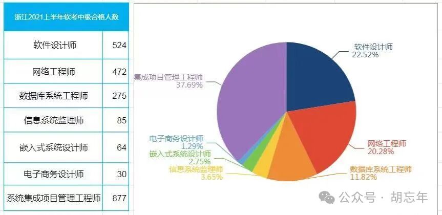
Interestingly, I started organizing a directory of high-frequency exam points in April for personal use.
But due to busy coursework, I had to rely on luck for the exam.
——If you are fortunate enough to stumble upon this private note, feel free to share and collect it, since you are already here.
Warning: Long and tedious notes ahead!!!
Since it is better to teach fishing than to give fish:
1. CPU related components (Computer Organization Principles – the basics)
● Program Counter (PC)
It is the place used to store the address of the next instruction. Before program execution, the starting address of the program, i.e., the address of the memory unit where an instruction is located, must be sent to the program counter. When executing instructions, the CPU will automatically modify the contents of the program counter, increasing it by one for each executed instruction, pointing to the next instruction to be executed. Program transfers and other operations are also implemented through this register.
● Memory Address Register (MAR)
Generally used to store the address of the memory unit currently accessed by the CPU, facilitating read and write operations to memory.
● Memory Data Register (MDR)
Primarily used to store operands and results of operations, aiming to save the time required for reading operands and accessing memory.
● Accumulator (ACC)
It is a register specifically for storing operands and results of arithmetic or logical operations.
● Arithmetic Logic Unit (ALU)
It is the execution unit of the CPU, mainly responsible for arithmetic operations.
● Instruction Register (IR)
Generally used to store the current instruction being executed.
2. Bus
Broadly speaking, any wire connecting two or more electronic components can be called a bus.
● Internal Bus
Used for interconnections at the chip level, divided into on-chip buses and component-level buses. On-chip buses are used for connections within integrated circuit chips, while component-level buses are used for connections among components on a circuit board.
● System Bus
Used for interconnections at the board level, forming connections among various components of a computer (CPU, memory, interfaces, etc.), such as: ISA bus, PCI bus, etc.
● External Bus
Also known as communication bus, used for interconnections at the device level, facilitating information and data exchange with other devices, such as: RS-232C, USB, SCSI, SATA bus, IEEE-1394, etc.
● Classification of Buses
Data Bus:
Transmits data information, the data transmitted by the CPU at one time is equal to the bandwidth of the data bus.
Control Bus:
Transmits control signals and timing signals, such as read/write, chip select, interrupt response signals, etc.
Address Bus:
Transmits addresses, determining the system’s addressing space.
3.Concepts Related to Computer Cycles
● Instruction Cycle (Instruction Cycle)
Time taken to fetch and execute an instruction.
● Bus Cycle (BUS Cycle)
Time taken for a memory or I/O port operation.
● Clock Cycle (Clock Cycle)
Also known as oscillation cycle, it is the most basic unit of processing operations. (The reciprocal of the crystal oscillator frequency)
● Relationship between Instruction Cycle, Bus Cycle, and Clock Cycle
A single instruction cycle consists of several bus cycles, while a bus cycle time contains several clock cycles.
A bus cycle includes one (only address cycle) or multiple machine cycles.
The CPU’s response to DMA occurs at the end of a machine cycle.
● Machine Cycle
Time unit for completing a basic operation, such as instruction fetch cycle, data fetch cycle.
4. Input and Output
● Memory and Interface Address Independent Compilation Method
Memory addresses and interface addresses are completely independent address spaces, fully isolated from each other. The instructions used to access data are also completely different; the instructions for interfaces are only used for interface read/write, while the rest are for memory. Therefore, it is easy to use and identify in programming or reading programs.
● Unified Addressing Method for Memory and Interface
Memory addresses and interface addresses are unified in a common address space, meaning memory units and interfaces share the address space. A portion of this address space is allocated for interface use, while the remaining addresses are for memory units. The address range allocated for memory can only be used by memory units, and the interface is not allowed to use it. Similarly, the address range allocated for the interface cannot be used by memory units. The advantage of this addressing method is that, in principle, all instructions used for memory can also be used for interfaces, with some allocated for interface use and the rest for memory, which often leads to non-contiguous memory addresses. When the instructions for memory and those for interfaces are identical, maintenance of the program requires careful identification based on the parameter definition table.
● Direct Program Control (Unconditional Transfer/Program Polling Method)
Unconditional Transfer:
In this case, the peripheral is always ready, capable of unconditionally receiving output data from the CPU at any time, and can also unconditionally provide input data to the CPU at any time.
Program Polling Method:
In this method, input and output are performed using polling, where the CPU executes a program to check the status of the peripheral, determining whether the peripheral is ready to receive data or has data ready to input to the CPU.
● Interrupt Method
Controlled by the program I/O method, its main disadvantage is that the CPU must wait for the I/O system to complete the data transfer task, during which the CPU needs to periodically check the I/O system’s status to confirm whether the transfer is complete. Therefore, the overall system performance is severely degraded.
● DMA
Refers to direct block transfer of data between memory and I/O devices, meaning that during the transfer of a data block between memory and I/O devices, no intervention from the CPU is required; only the CPU needs to initiate the process (i.e., issue a command to the device to “transfer a block of data”) and handle the end of the process ( the CPU learns whether the process has ended and whether the next operation is ready through polling or interrupts). The actual operation is completed directly by the DMA hardware, allowing the CPU to perform other tasks during this transfer.
5.Characteristics of Embedded Software Systems
● Smaller scale.
● High development difficulty.
(Limited hardware resources; embedded software generally involves the development of low-level software, requiring both software and hardware foundations; the development environment and operating environment are different.)
● High requirements for real-time performance and reliability. For example, rocket flight control, nuclear power plants.
● Requires fixed storage.
6.Embedded Software Architecture
● Device Driver Layer
Also known as Board Support Package (BSP): contains all hardware-related code in embedded systems.
Most embedded hardware devices require some type of software initialization and management. This part of the work is done by the device driver layer, which is responsible for directly interacting with hardware, managing and controlling hardware, and providing the necessary driver support for upper-layer software, similar to BIOS and drivers in PC systems.
● Operating System Layer
Embedded operating systems are operating systems that work in embedded environments. The functions of embedded operating systems can be described from two aspects:
(1) From the perspective of software development, the EOS can be seen as an extended machine or virtual machine. It encapsulates the underlying hardware details, providing an abstract programming interface for the software running on it, i.e., the system call functions provided by the operating system.
(2) From the perspective of system management, the EOS can be seen as the manager of system resources, responsible for managing various software and hardware resources in the system.
7.Process
● Process
Is the process of a program running on a data set, and it is an independent unit for resource allocation and scheduling in the system. It consists of a program block, a process control block ( PCB), and a data block.
● Three-State Description
Running State: Occupies the processor and is currently running.
Ready State: Indicates that it meets the running conditions and is waiting for the system to allocate the processor for execution.
Waiting State: Also known as blocked state or sleep state, indicates that it does not meet the running conditions and is waiting for the completion of a certain event.
● Transition between Three States
Running State – Waiting State: Waiting for resource usage, such as waiting for peripheral transmission, waiting for manual intervention.
Waiting State – Ready State: Resources are satisfied, such as peripheral transmission completion, manual intervention completion.
Running State – Ready State: Running time slice is up, a higher priority process appears.
Ready State – Running State: The CPU selects a ready process when it is idle.
8.Process Control
● Process Control
Is the effective control of all processes in the system from creation to termination; implemented by primitives in the operating system kernel.
● Primitive: Refers to a program segment composed of several machine instructions used to complete specific functions; the characteristic of a primitive is that it cannot be divided during execution, i.e., atomic operations are either fully executed or not executed at all.
● Synchronization/Mutual Exclusion
Synchronization: Direct constraints between cooperating processes.
Mutual Exclusion: Indirect constraints between processes requesting critical resources.
Critical Resource: Refers to resources that can only be used by one process at a time.
Critical Section: The segment of the program where operations on critical resources are performed.
9.Semaphore Mechanism
● Semaphore
Is an integer variable assigned different values based on the control object. It can be divided into public semaphores and private semaphores.
● Public Semaphore
Implements mutual exclusion between processes, with an initial value of 1 or the number of resources.
● Private Semaphore
Implements synchronization between processes, with an initial value of 0 or some positive integer.
● Physical Meaning of Semaphore S
S>=0 indicates the number of available resources; S<0, its absolute value indicates the number of processes waiting for that resource in the blocking queue.
● PV Operations
Are commonly used methods for implementing process synchronization and mutual exclusion, P operation and V operation are low-level communication primitives that cannot be divided during execution; among them, P operation indicates requesting a resource, while V operation indicates releasing a resource.
Definition of P Operation:
S:=S-1, if S>=0, then the process executing the P operation continues; if S<0, then set the process to a blocking state (because there are no available resources) and insert it into the blocking queue.
Definition of V Operation:
S:=S+1, if S>0, then the process executing the V operation continues; if S<=0, then wake up a process from the blocking state and insert it into the ready queue, then the process executing the V operation continues.
10.Thread
● Two Basic Attributes
It is an independent unit that can own resources.
It is the basic unit that can be independently scheduled and allocated.
● Relationship between Threads and Processes
Threads are the basic unit of scheduling and allocation, while processes are the units of independent resource allocation.
Threads are entities within a process.
● Threads only own the necessary resources for execution: program counter, a set of registers, stack.
Threads can share all resources owned by the process they belong to.
● Thread Classification
User-level threads, kernel-supported threads.
11. Task Scheduling
● Scheduling Methods
(1) Non-preemptive scheduling method: If a task is selected by the scheduler, it will run continuously until it is blocked for some reason (such as I/O operations or synchronization between tasks) or it voluntarily relinquishes the use of the CPU.
(2) Preemptive scheduling method:
When a task is running, the scheduler can interrupt it and schedule other tasks to run.
● Priority Inversion
Occurs when a high-priority task needs to wait for a low-priority task to release resources, while the low-priority task is waiting for a medium-priority task.
● Real-time System Scheduling
(1) Rate Monotonic Scheduling Algorithm: A static priority scheduling algorithm, the most commonly used algorithm for determining task priorities.
The priority of a task is a monotonic function of its period; the shorter the task period, the higher the priority, and the longer the task period, the lower the priority.
MS assumes that tasks are independent, periodic, and can be preempted at any point; however, in actual systems, tasks need to communicate and synchronize, making this an ideal scheduling method that may not always exist in practice.
(2) Earliest Deadline First Scheduling Algorithm: A dynamic priority scheduling algorithm, currently one of the better-performing scheduling algorithms.
Prioritizes tasks based on their deadline; the task with the nearest deadline is assigned the highest priority.
When a new task enters the ready state, the priorities of all tasks may need to be adjusted, selecting the task with the nearest deadline to run.
● Inter-task Communication
Tasks need to exchange data and control information to coordinate work. Inter-task communication can be divided into two types:
(1) Low-level communication: Can only transmit state and integer values, such as semaphore mechanisms, asynchronous signal mechanisms.
(2) High-level communication: Can transmit arbitrary amounts of data, mainly divided into three categories: shared memory, message passing, and pipes.
12. OSI Seven-Layer Model (Key Exam Focus)
● Physical Layer
Provides the mechanical, electrical, functional, and procedural characteristics required to establish, maintain, and dismantle physical links;
Provides information about transmitting unstructured bit streams over transmission media and indications of physical link fault detection.
Unit: bits, Bit.
Related Devices: Hub, Repeater.
● Data Link Layer
Responsible for error-free transmission of data in frames between two adjacent nodes and for flow control.
Unit: frames.
Related Devices: Bridge, Switch.
● Network Layer
Provides end-to-end exchange network data transmission functions for transport layer entities, freeing the transport layer from routing, switching methods, and congestion control details;
Can establish, maintain, and dismantle one or more communication paths for transport layer entities;
Reports unrecoverable errors occurring during network transmission.
Unit: packets.
Related Devices: Router, Layer 3 Switch.
● Transport Layer
Provides transparent, reliable data transmission services for session layer entities, ensuring end-to-end data integrity;
Selects the most suitable service provided by the network layer, providing functions for establishing, maintaining, and dismantling transport connections.
Unit: segments.
● Session Layer
Provides functions for establishing, maintaining, and terminating session connections for cooperating presentation layer entities, completing the correspondence between logical names and physical names in the communication process, providing session management services.
● Presentation Layer
Provides a set of services for interpreting the meaning of exchanged information for application layer processes, i.e., converting data to be exchanged from a syntax suitable for a specific user to a syntax suitable for internal use by the OSI system.
● Application Layer
Provides OSI user services, determining the nature of communication between processes to meet user needs and providing interface services between the network and user application software.
13. Concepts Related to Network Attacks
● Impersonation
Refers to an entity pretending to be a different entity. Often used in conjunction with active attack forms, especially message replay and tampering.
● Replay
Occurs when a message or part of a message is repeated to produce unauthorized effects.
● Message Tampering
Data transmitted is altered without detection, leading to unauthorized consequences.
● Denial of Service
Occurs when an entity cannot perform its normal functions, or its actions hinder other entities from performing their normal functions.
14.Symmetric Encryption Algorithms
Symmetric key cryptography refers to a cryptographic system where the encryption key and decryption key are the same.
Common symmetric key encryption algorithms: Data Encryption Standard DES, 3DES (Triple DES), RC-5, IDEA algorithm, AES algorithm.
15. Asymmetric Encryption Algorithms
Public key cryptography refers to a cryptographic system where the encryption key and decryption key are different; in public key cryptography, the encryption key PK (public key) is made public, while the decryption key SK (secret key) must be kept confidential. The encryption algorithm E and decryption algorithm D are also public.
Common asymmetric key encryption algorithms: RSA, Elgamal, ECC.
16.Compiler Working Process
● Lexical Analysis Stage
It is the first stage of the compilation process, tasked with scanning the source program from front to back (left to right), identifying individual “words” or tokens. The lexical analysis process is based on the language’s lexical rules, which describe the structure of “words”.
● Syntax Analysis Stage
Its task is to decompose the sequence of word symbols into various grammatical units based on the language’s syntax rules, based on lexical analysis. Generally, syntax analysis determines whether the entire input string constitutes a syntactically correct program. In general, programs that pass compilation do not contain syntactic errors.
● Semantic Analysis Stage
Its main task is to check whether the source program contains static semantic errors and to collect type information for use in the subsequent code generation stage. A major task of semantic analysis is type analysis and checking.
● Intermediate Code Generation
Its task is to generate intermediate code based on the output of semantic analysis.
● Target Code Generation
It is the final stage of the compiler’s work. Its task is to transform intermediate code into absolute instruction code, relocatable instruction code, or assembly instruction code specific to a particular machine. This stage is closely related to specific machines.
● Symbol Table Management
The symbol table’s role is to record necessary information about each symbol in the source program to assist in checking semantic correctness and code generation. During the compilation process, fast and efficient operations such as searching, inserting, modifying, and deleting in the symbol table are required.
17.Software Configuration Management
(1) Development Library (Dynamic Library, Programmer Library, Working Library; Dynamic System, Developer System, Development System, Working Space).
(2) Controlled Library (Main Library, System Library; Main System, Controlled System).
(3) Product Library (Backup Library, Static Library, Software Repository; Static System).
(4) Checkpoint: Refers to checking the project at specified intervals, comparing actual results with plans, and making adjustments based on discrepancies.
(5) Milestone: A marker for completing phase work; different types of projects have different milestones.
(6) Baseline: Refers to a configuration item (or a group of configuration items) that has entered a formally controlled state through formal review at different points in the project lifecycle. A baseline is an important milestone, but the related deliverables must undergo formal review and serve as a benchmark and starting point for subsequent work. Once established, changes to a baseline must be controlled.
● Functional Baseline (Design Baseline)
It refers to the system design specification document that has been formally reviewed and approved at the end of the system analysis and software definition phase, which is the functional baseline.
● Allocated Baseline (Requirements Baseline)
Also known as assigned baseline, it refers to the software requirements specification document (SRS) that has been formally reviewed and approved at the end of the software requirements analysis phase.
● Product Baseline
It refers to the specification of all configuration items related to the developed software product that has been formally reviewed and approved at the end of the software assembly and system testing phase.
18.Capability Maturity Model
The Software Process Capability Maturity Model (Capability Maturity Model of Software, CMM) describes the stages of evolution of software organizations. This capability maturity model allows software organizations to easily determine their current process maturity and identify weaknesses in their software process execution, determining the most critical issues for software quality and process improvement, thus forming improvement strategies for their processes.
● Initial Level
The characteristics of the software process are disordered, sometimes even chaotic.
● Repeatable Level
Basic project management processes have been established, which can be used to track costs, schedules, and functional characteristics.
● Defined Level
Software processes used for management and engineering are documented, standardized, and form the standard software process for the entire software organization.
● Managed Level
Software processes and product quality have detailed measurement standards.
● Optimizing Level
Through quantitative analysis of useful information from processes, new concepts, and new technologies, continuous and ongoing process improvements can be made.
19.Aggregation
Measures the degree of closeness of the combination of elements within a module.
● Accidental Aggregation
Actions completed by the module have no relationship or only a very loose relationship.
● Logical Aggregation
Components within the module have similar processing actions logically, but are functionally unrelated.
● Temporal Aggregation
Processing actions contained within the module must be executed at the same time.
● Process Aggregation
Actions to be completed by various components within the module, although unrelated, must be executed in a specific order.
● Communication Aggregation
Actions completed by various components of the module use the same data or produce the same output data.
● Sequential Aggregation
Components within the module, the final output of the previous component’s processing action is the input for the next component’s processing action.
● Functional Aggregation
All parts within the module belong to a whole and perform the same function, and each part is essential for achieving that function.
20.Coupling
Measures the degree of interdependence between different modules.
● Non-direct Coupling: There is no direct relationship between two modules; their connection is entirely achieved through control and calls from a main module.
● Data Coupling: Two modules exchange information through data parameters.
● Label Coupling: A group of modules passes record information through parameter tables, where the record is a substructure of a certain data structure, rather than a simple variable.
● Control Coupling: The information passed between two modules contains control information.
● External Coupling: A group of modules accesses the same global simple variable rather than the same global data structure, and this global variable’s information is not passed through parameter tables.
● Common Coupling: Two modules pass information through a common data area.
● Content Coupling: One module needs to involve the internal information of another module.
21. Software Testing
● Testing Concepts
Classic definition: Operating the program under specified conditions to discover errors and assess software quality.
● Types of Software Testing
Divided by development stage:
Unit Testing, Integration Testing, System Testing, Confirmation Testing, Acceptance Testing.
Divided by testing technique:
White-box Testing, Black-box Testing, Gray-box Testing.
● White-box Testing
Also known as structural testing or logic-driven testing, it tests the program according to its internal structure, checking whether the internal actions of the product proceed normally according to the design specifications, verifying whether each path in the program can work correctly as required.
Logical Coverage Method:
Statement Coverage (SC): Design enough test cases to ensure that each statement in the tested program is executed at least once.
Decision Coverage (DC): Design enough test cases to ensure that each decision in the program obtains at least one “true” or “false” value. Also known as branch coverage: ensures that each “true” branch and “false” branch in the program is executed at least once.
Condition Coverage (CC): Design enough test cases to ensure that each logical condition in each decision statement satisfies its possible values at least once.
Condition-Decision Combination Coverage (CDC): Design enough test cases to ensure that all possible (true/false) values of each condition in the decision appear at least once, and that the result of each decision itself (true/false) also appears at least once.
-
Path Coverage:
Refers to covering all possible paths in the tested program.
-
Basic Path Method:
Based on the program control flow graph, it derives a set of executable paths by analyzing the complexity of loops in the control flow graph, thus designing test cases.
● Black-box Testing
Also known as functional testing: discovers defects and errors through the external performance of the software.
Black-box testing treats the test object as a black box, completely ignoring the internal structure and processing of the program; black-box testing is performed at the program interface, checking whether the program operates normally according to the requirements specification.
22.Linear List
It is the most commonly used and simplest data structure. A linear list is a finite sequence of n data elements. A data element can consist of several data items, commonly referred to as records.
23.Stack (Stack)
It is a special type of linear list, limited to performing insertion or deletion operations only at the end of the list. The end where insertion and deletion occur is called the top of the stack, while the other end is the bottom of the stack.
Characteristics: Last In, First Out.
24.Queue (Queue)
It is a linear list that only allows insertion at one end and deletion at the other end, making it a restricted linear list. The end where insertion occurs is called the rear of the queue, while the end where deletion occurs is called the front of the queue.
Characteristics: First In, First Out.
25.Concept of Combinational Logic Circuits
Logic circuits are divided into two types based on whether they have storage functions: combinational logic circuits and sequential logic circuits.
● Combinational Logic Circuits
Combinational logic circuits do not contain storage functions; their output values depend solely on the current input values. Common combinational logic circuits include: decoders, multiplexers, etc.
● Sequential Logic Circuits
Sequential logic circuits contain storage functions; their output values depend not only on the current input state but also on the values in the storage units. Common sequential logic circuits include: registers, counters, etc.
26.Level Conversion Circuits
● TTL → CMOS Conversion:
CMOS logic levels: VCC: 5V; Voh>=4.45V; Vol<=0.5V; Vih>=3.5V; Vil<=1.5V. Very wide noise margin.
TTL logic levels: VCC: 5V; Voh>=2.4V; Vol<=0.4V; Vih>=2.0V; Vil<=0.8V. Noise margin is 0.4V.
In the TTL circuit, a pull-up resistor R is connected between the output terminal and the power supply, and the value of R is determined by the TTL’s Ioh.
● CMOS → TTL Conversion:
CMOS logic levels: VCC: 5V; Voh>=4.45V; Vol<=0.5V; Vih>=3.5V; Vil<=1.5V. Very wide noise margin.
TTL logic levels: VCC: 5V; Voh>=2.4V; Vol<=0.4V; Vih>=2.0V; Vil<=0.8V. Noise margin is 0.4V.
TTL circuit input short-circuit current is large, requiring the CMOS circuit to provide sufficient drive current when VOL is 0.5V;
Interface devices: CC4049, CC4050.
27.Classification of Embedded Microprocessors
● Embedded Microcontroller (MCU: Micro Controller Unit): Also known as a single-chip microcontroller, it generally has rich on-chip peripheral resources and is suitable for control.
● Embedded Microprocessor (EMPU: Embedded Micro Processing Unit): Also known as a single-board computer, it is developed from the CPU in general computers, retaining only the hardware functions closely related to embedded applications.
● Embedded DSP Processor (DSP: Digital Signal Processor): A processor specifically used for signal processing.
● Embedded System on Chip (SoC): Pursues maximum integration of product systems. (Such as most mobile phone chips commonly referred to in daily life)
28.Interrupt System
Interrupt: During the execution of a program by the CPU, it randomly receives interrupt requests from peripherals, allowing the CPU to temporarily interrupt the currently executing program and switch to the corresponding interrupt service (sub) program for processing (interrupt response and interrupt service). After processing, it returns to the original program (the point of interruption) (interrupt return) and continues running; this process is called an interrupt.
When the interrupt system is executing an interrupt service, if another higher-priority interrupt requests an interrupt, it will temporarily terminate the service program of the currently executing lower-priority interrupt source to handle the higher-priority interrupt source. After processing, it returns to the interrupted interrupt service program to continue execution; this process is called interrupt nesting.
Interrupt Response Time: The time from issuing an interrupt request to entering interrupt processing.
Interrupt Processing Time: The time from the start of interrupt processing to the end of interrupt processing.
Interrupt Response Process:
1. Protecting the context: Saving the current address, accumulator ACC, and status register to the stack.
2. Switching the PC: Switching to the corresponding interrupt entry address based on the different interrupt sources generated.
3. Executing the interrupt service handler.
4. Restoring the context: Restoring the main program address, accumulator ACC, and status register saved in the stack.
5. Interrupt return: Returning from the interrupt point to the main program and continuing execution.
Interrupt entry address: Each interrupt source is assigned a different interrupt entry address in the microcontroller, also known as an interrupt vector.
29. Flash
Flash memory is an important component in embedded systems, used to store programs and data, and data is not lost after power off.
However, when using Flash Memory, special design of the storage system must be made according to its characteristics to ensure optimal system performance.
Flash Memory is a type of non-volatile memory (NVM: Non-Volatile Memory), which can be divided into:
NOR Flash, NAND Flash.
Applications can run directly in NOR Flash without needing to read the code into system RAM to run. NAND Flash needs to be downloaded to RAM before it can run.
30. A/D Interface Principles and Interfaces
● Counting Method
The counting-type A/D converter circuit mainly includes: comparator, counter, D/A converter, and standard voltage source. The counter starts counting from 0, adding 1 each time, and this value serves as the input to the D/A converter, generating a comparison voltage Vo to compare with the input analog voltage Vi. If Vo is less than Vi, it continues to count up by 1 until Vo exceeds Vi, at which point the accumulated value of the counter is the output value of the A/D converter.
● Dual Integration Method
The dual integration A/D conversion method circuit mainly includes: integrator, comparator, counter, and standard voltage source.
It performs two integrations on the input analog voltage and reference voltage, converting the voltage into a time interval proportional to it, using clock pulses and counters to measure the time interval, completing the A/D conversion.
● Successive Approximation Method
The successive approximation A/D conversion method circuit mainly includes: comparator, D/A converter, successive approximation register, and reference voltage source.
Essentially, it is a binary search method, similar to the principle of using a balance scale.
During A/D conversion, the D/A converter increases the conversion bit from high to low one bit at a time, generating different output voltages, comparing the input voltage with the output voltage to achieve conversion.
First, set the highest bit of the successive approximation register to 1, which is equivalent to comparing the reference voltage of 1/2 with the input voltage. If the input voltage is less than 1/2 of the reference voltage, set the highest bit to 0; otherwise, set it to 1. Then, set the next highest bit to 1, which is equivalent to performing a binary search within the range of 1/2, and so on, approaching successively.
31. D/A Interface Principles and Interfaces
● D/A Converter Working Principle
A 4-bit R-2R resistor network DAC circuit. The circuit consists of an R-2R resistor decoding network, analog electronic switches, and summing amplifiers. Because R and 2R form a T-type, it is called a T-type resistor network DAC.
● Resolution:
The minimum output voltage that the DAC circuit can distinguish compared to the full-scale output voltage is called the DAC’s resolution. The minimum output voltage refers to the output voltage when the input digital quantity has only the least significant bit as 1, while the maximum output voltage refers to the output voltage when all bits of the input digital quantity are 1. The resolution of the DAC can be expressed as: resolution = 1/(2n – 1), where n represents the number of binary bits of the digital quantity.
32.Basic Principles and Structures of Serial Interfaces
Serial communication: Data is transmitted one bit at a time, with each bit of data occupying a fixed time length during transmission. There are three basic communication modes for serial data transmission: simplex, half-duplex, and full-duplex communication. Serial communication can be divided into asynchronous communication and synchronous communication in terms of information format.
33.Basic Principles and Structures of Parallel Interfaces
Parallel communication typically transmits each bit of a data byte simultaneously using multiple data lines. It is generally used to connect printers, scanners, etc., and is also known as a printer port.
Characteristics: Simple control, fast transmission speed.
Due to the large number of transmission lines, the cost of long-distance transmission is high, and simultaneous reception of each bit by the receiver poses difficulties.
34.Related Buses
|
Bus Name |
Bus Classification |
Communication Method |
Remarks |
|
RS232C |
External Bus |
Serial communication, full-duplex |
RS-232C is a serial communication interface standard established by the Electronic Industries Association (EIA) of the United States. |
|
RS422 |
External Bus |
Serial communication, full-duplex |
RS-422 standard is an improved version of RS-232, a unidirectional, balanced transmission specification for single machine sending and multiple machines receiving, with a transmission rate of up to 10Mb/s. It uses differential transmission, also known as balanced transmission. |
|
RS485 |
External Bus |
Serial communication, half-duplex |
Based on RS-422, the EIA established the RS-485 standard to expand the application range, adding multi-point, bidirectional communication capabilities. |
|
IEEE488 |
External Bus |
Bit parallel, byte serial communication, standard |
General-purpose interface bus, 8 bits, transmission distance 20m, maximum transmission speed of 1Mb/s, up to 15 devices can be connected on this bus. Used in instruments, meters, and measurement and control fields. |
|
SCSI |
External Bus |
Parallel communication, standard |
Small Computer System Interface, 8-bit or 32-bit. Transmission distance 6m, speed up to 5Mb/s. Used for connecting computers with tape drives, floppy disk drives, hard disk drives, CDROMs, rewritable optical disks, scanners, communication devices, and printers. |
|
MXI |
External Bus |
Parallel communication, non-standard |
Multi-system expansion interface bus, 32-bit high-speed parallel bus. Distance up to 20m, speed up to 23Mb/s. Used for connecting computers with measurement and control chassis. |
|
PCI |
System Bus |
Parallel communication |
Peripheral Component Interconnect bus, 32-bit or 64-bit. Local bus, maximum operating frequency of 33MHz, data transfer rate of 132Mbps (32-bit) and 264Mbps (64-bit). Mainly used to connect display cards, network cards, sound cards, IDE interface cards, etc. |
|
USB |
External Bus |
Serial bus |
Universal Serial Bus. Connects computers with external devices. Used for data communication with various embedded system devices, such as mobile hard drives, PDAs. |
|
SPI |
Internal Bus |
Serial bus, full-duplex |
Serial Peripheral Interface. It is a 4-wire interface mainly used for connecting microcontrollers (MCUs) with peripheral device chips, and can be used to connect memory, A/D converters, D/A converters, real-time clock calendars, LCD drivers, sensors, audio chips, and other processors. |
|
IIC |
Internal Bus |
Serial bus, |
Internal integrated circuit bus, a two-wire serial expansion bus used to connect microcontrollers and their peripheral devices. |
|
IEEE1394 |
External Bus |
Serial bus, half-duplex |
It is a high-quality, high-speed serial bus technology first proposed by Apple, recognized as a serial industrial bus standard by IEEE in 1995. Used in real-time multimedia fields, large-capacity storage, and on printers, scanners, etc. |
|
CAN Bus |
External Bus |
Serial bus, half-duplex |
CAN, short for “Controller Area Network”, is one of the most widely used field buses internationally. |
|
SCI |
External Bus |
Synchronous serial, full-duplex |
Serial communication interface, relative to parallel communication, is a general term for serial communication technology, first proposed by Motorola. Includes synchronous and asynchronous serial communication. RS232, RS422, RS485, etc. are all SCI. |
|
UART |
External Bus |
Asynchronous serial, full-duplex |
Universal Asynchronous Receiver-Transmitter. |
35. PCB Reliability Design in PCB Design
● Ground Design
In electronic devices, grounding is an important method for controlling interference.
Correctly choose between single-point grounding and multi-point grounding.
In low-frequency circuits (operating frequency less than 1MHz), use single-point grounding.
In high-frequency circuits (operating frequency greater than 10MHz), use nearby multi-point grounding.
Separate digital circuits from analog circuits; do not mix their ground lines. Connect them separately to the power supply ground line.
Try to thicken the ground line. If the ground line is too thin, the grounding potential will change with current variations; if possible, the width of the ground line should be greater than 3mm.
Forming a closed loop with the ground line can significantly improve noise immunity.
● Electromagnetic Compatibility Design
Electromagnetic compatibility (EMC) refers to the ability of a device or system to operate satisfactorily in its electromagnetic environment without causing unacceptable electromagnetic interference to any devices in that environment.
Choose reasonable wire widths.
Use correct wiring strategies: it is best to use a grid-like wiring structure.
Suppress reflection interference.
● Decoupling Capacitor Configuration
Configuring decoupling capacitors can suppress noise generated by load changes, which is a common practice in the reliability design of printed circuit boards. The configuration principles are as follows:
Place a 10~100uF electrolytic capacitor across the power input.
Configure a 0.01uF ceramic capacitor for each integrated circuit chip.
For devices with weak noise immunity and large current changes when turned off, as well as storage devices like ROM and RAM, a decoupling capacitor should be directly connected between the chip’s power line and ground line.
The leads of the decoupling capacitor should not be too long.
● PCB Size and Component Configuration
Components that are interrelated should be placed as close together as possible.
Clock generators, crystal oscillators, and the clock input terminals of the CPU are prone to interference and should be placed close to each other.
Components that generate noise, low-current circuits, and high-current circuits should be kept as far away from logic circuits as possible.