In the previous article, we implemented some PnP callbacks in PCI drivers, allowing the driver to load onto the PCIe device and enabling the device to enter the D3 low power state. In essence, writing a driver involves using the APIs provided by the operating system’s driver framework to create device objects and implement various callbacks that allow the operating system to interact with hardware devices from user mode applications to kernel mode modules. When it comes to interacting with hardware devices, there are primarily three forms: register access, DMA, and interrupts. For PCI/PCIe devices, register access mainly includes two forms: accessing PCI configuration space registers and accessing MMIO (Memory-Mapped I/O) registers. This article will introduce how to access these two types of registers in a PCI driver.In Windows PCI drivers, there are mainly three methods to access PCI configuration space registers.1. Through the BUS_INTERFACE_STANDARD interface.2. Through the IRP_MN_READ_CONFIG and IRP_MN_WRITE_CONFIG IRPs.3. Using the HalGetBusDataByOffset and HalSetBusDataByOffset functions.The first method is more suitable for WDF drivers, the second method is suitable for WDM drivers, and the third method is primarily for backward compatibility and is generally not recommended for use today. Since the PCI driver we are writing is a WDF driver, we will introduce the first method below.First, we need to query whether the current device has the BUS_INTERFACE_STANDARD interface, which has the GUID GUID_BUS_INTERFACE_STANDARD. We use the API function WdfFdoQueryForInterface provided by the WDF driver framework to obtain this interface. This function requires the WDFDEVICE handle of the current PCI device and the GUID representing the interface type:GUID_BUS_INTERFACE_STANDARD, which returns a BUS_INTERFACE_STANDARD structure representing the bus interface. The specific code is as follows. We added a BusInterface member to the DEVICE_CONTEXT to store the obtained BUS_INTERFACE_STANDARD structure. Since querying the bus interface requires a WDFDEVICE handle, this code needs to be placed after the successful call to WdfDeviceCreate.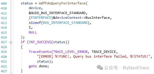 After obtaining the bus interface, we can call the GetBusData or SetBusData functions on this interface to access the PCI configuration space. For example, to read the Vendor ID and Device ID registers in the PCI configuration space, we only need to pass the offset and length of the configuration space registers to GetBusData. The offsets for the Vendor ID and Device ID registers in the PCI configuration space are 0 and 2 respectively (we defined macros VID_OFFSET and DID_OFFSET to represent these), and both registers are 2 bytes in length. We added two members in the DEVICE_CONTEXT structure to store the obtained Vendor ID and Device ID.
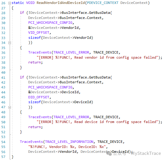 In the driver, we often need to save the obtained Device ID information as shown above, because a driver may be used on multiple versions of a device. For different versions of hardware, the driver’s handling may vary, and the driver can determine the current device version based on the Device ID at runtime, thus selecting different processing logic.Accessing MMIO registers in PCI drivers is relatively straightforward. As mentioned earlier, in the PrepareHardware function of WDF drivers, we can enumerate all the physical base addresses of the MMIO registers for this PCI device. What we need to do is map these physical base addresses of the MMIO registers to the kernel virtual address space to obtain the virtual base address of the MMIO registers, after which we can access the MMIO registers as if we were accessing memory using pointers. The Windows kernel provides the MmMapIoSpace function to map the MMIO physical base address to a virtual address. It is important to note that when mapping, we need to use the MmNonCached CacheType, because the virtual address obtained from the mapping corresponds to the device’s registers and is not actual physical memory. Using a NonCached mapping can avoid cache coherence issues when accessing registers. If a Cached mapping is used, there are two main issues: when reading registers, the CPU may read an old value from the cache instead of the latest state from the hardware, and when writing to registers, the write operation may be cached and not reach the hardware in a timely manner, which can lead to abnormal device operation. The following code performs MMIO mapping when enumerating MMIO type resources in the PrepareHardware function. Since this PCIe device has two BARs, we added two arrays of length 2 in the DEVICE_CONTEXT structure to store the mapped virtual addresses (MmioBase) and the lengths of the mapped registers (MmioSize).
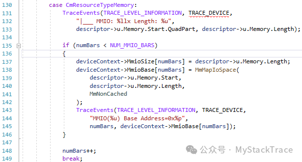 As mentioned earlier, the operations performed in the PrepareHardware function need to be reversed in the ReleaseHardware function (which is called when unloading the driver or removing the device). For MmMapIoSpace, the reverse operation is MmUnmapIoSpace.
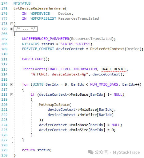 It was also mentioned in previous articles that the DEVICE_CONTEXT structure is used to store some context information about this device, so we placed the obtained bus interface and the mapped MMIO virtual base addresses in this structure. The current effect is as follows.
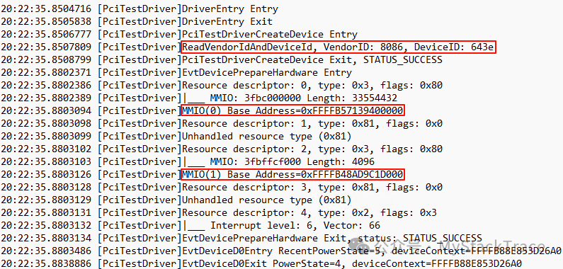
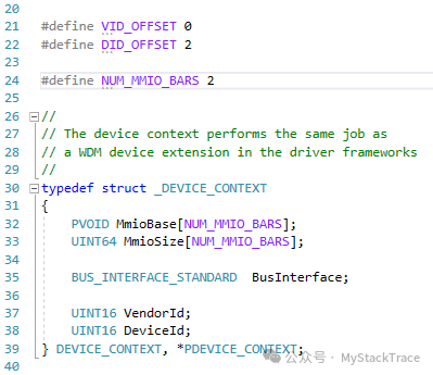 After modifying the code, compiling, signing, and installing, let’s check the installation log of the driver. We successfully printed the VendorID and DeviceID, indicating that we successfully obtained the bus interface and accessed the PCI configuration space using the bus interface. Additionally, the mapping of the MMIO base address is also correct, and we successfully obtained the mapped MMIO virtual base address.