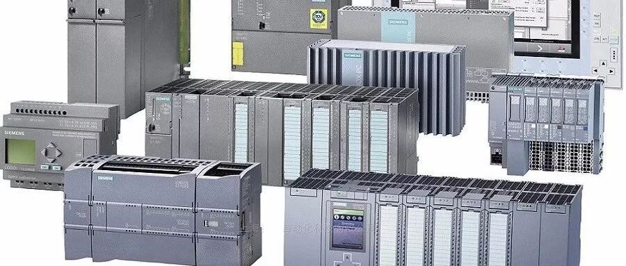
1. Definition and Classification of PLC
PLC (Programmable Logic Controller) is a new generation of general industrial control device based on microprocessor technology, integrating computer technology, automatic control technology, and communication technology. It uses user-friendly “natural language” programming for control processes, making it suitable for industrial environments, easy to understand, convenient to operate, and highly reliable.
PLC is developed from relay sequential control and is a general automatic control device centered around a microprocessor.
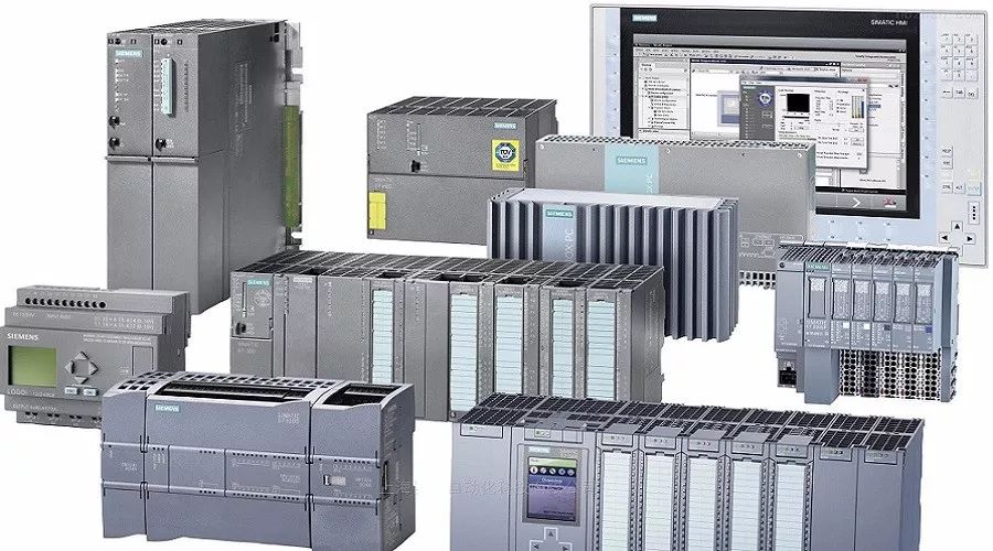
1. Definition of PLC
A Programmable Logic Controller is a digital operation electronic system designed specifically for application in industrial environments.
It uses programmable memory to internally store instructions for executing logical operations, sequential control, timing, counting, and arithmetic operations, and controls various types of machinery or production processes through digital and analog inputs and outputs.
Programmable Logic Controllers and their related peripheral devices should be designed based on the principles of easy integration with industrial control systems and ease of functional expansion.
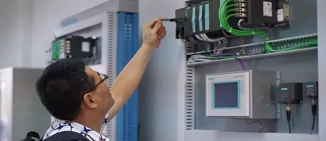
2. Classification of PLC
PLC products come in various types, with different specifications and performance. PLCs are generally classified based on their structural form, functional differences, and the number of I/O points.
2.1. Classification by Structural Form
According to the structural form of PLCs, they can be divided into two categories: integrated and modular.
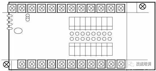
(1) Integrated PLC
Integrated PLCs have all components such as power supply, CPU, and I/O interfaces concentrated in one chassis, as shown in the figure. They are characterized by compact structure, small size, and low cost. Small PLCs generally adopt this integrated structure.
Integrated PLCs consist of basic units (also known as hosts) with different I/O points and expansion units. The basic unit contains the CPU, I/O interfaces, expansion ports connected to I/O expansion units, and interfaces connected to programmers or EPROM writers; the expansion unit contains only I/O and power supply, without a CPU. Basic and expansion units are generally connected by flat cables. Integrated PLCs can also be equipped with special function units, such as analog units and position control units, to expand their functionality.
(2) Modular PLC
Modular PLCs consist of several separate modules for each component, such as CPU modules, I/O modules, power supply modules (some included in the CPU module), and various functional modules. Modular PLCs consist of a frame or base and various modules, which are inserted into sockets on the frame or base, as shown in the figure.
This modular structure allows for flexible configuration, enabling the selection of different system scales as needed, and is easy to assemble, expand, and maintain. Medium and large PLCs generally adopt a modular structure.
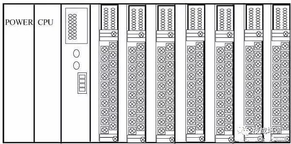
Some PLCs combine the characteristics of both integrated and modular types, forming what is known as stackable PLCs. Stackable PLCs have independent modules for CPU, power supply, and I/O interfaces, but they are connected by cables and can be stacked layer by layer. This not only allows for flexible system configuration but also enables compact design.
2.2. Classification by Function
Based on different functions, PLCs can be classified into low-end, mid-range, and high-end categories.
(1) Low-end PLC
Low-end PLCs have basic functions such as logical operations, timing, counting, shifting, self-diagnosis, and monitoring, and may also have a small number of analog inputs/outputs, arithmetic operations, data transfer, comparison, and communication functions. They are mainly used for logical control, sequential control, or single-machine control systems with limited analog control.
(2) Mid-range PLC
Mid-range PLCs have all the functions of low-end PLCs, along with stronger analog input/output capabilities, arithmetic operations, data transfer and comparison, number system conversion, remote I/O, subroutine, and communication networking functions. Some may also add interrupt control, PID control, etc., suitable for complex control systems.
(3) High-end PLC
High-end PLCs have all the functions of mid-range PLCs, plus additional capabilities for signed arithmetic operations, matrix operations, bitwise logical operations, square root operations, and other special function calculations, tabulation, and table transfer functions. High-end PLCs have stronger communication networking capabilities and can be used for large-scale process control or form distributed network control systems, thus achieving factory automation.
2.3. Classification by I/O Points
Based on the number of I/O points, PLCs can be classified into small, medium, and large categories.
(1) Small PLC
Small PLCs have fewer than 256 I/O points, with a single CPU and an 8-bit or 16-bit processor, and a user memory capacity of less than 4KB. For example: Mitsubishi FX0S series.
(2) Medium PLC
Medium PLCs have 256 to 2048 I/O points, with dual CPUs and a user memory capacity of 2 to 8KB.
(3) Large PLC
Large PLCs have more than 2048 I/O points, with multiple CPUs and 16-bit or 32-bit processors, and a user memory capacity of 8 to 16KB.
Globally, PLC products can be divided into three major factions by region: American products, European products, and Japanese products. The PLC technologies in the US and Europe were developed independently under isolation, resulting in significant differences between American and European PLC products. Japanese PLC technology was introduced from the US, inheriting some characteristics of American PLC products, but Japan primarily focuses on small PLCs. The US and Europe are known for medium and large PLCs, while Japan is renowned for small PLCs.
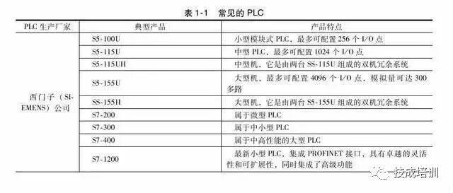
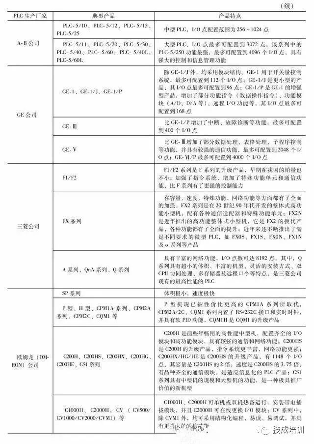
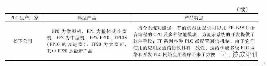
Common PLCs are shown in the table below:
2. Functions and Application Areas of PLC
PLC is designed and developed by integrating the advantages of relay contactor control with the flexibility and convenience of computers, which gives PLC many characteristics that other controllers cannot compare.
1. Functions of PLC
PLC is a general industrial automatic control device developed based on microprocessor technology, integrating computer technology, automatic control technology, and communication technology. It has a series of advantages such as high reliability, small size, strong functionality, simple and flexible program design, and easy maintenance, making it widely used in metallurgy, energy, chemical, transportation, and electric power industries, becoming one of the three pillars of modern industrial control (PLC, robots, and CAD/CAM). Based on the characteristics of PLC, its functional forms can be summarized as follows:
(1) Digital Logic Control
PLC has powerful logical operation capabilities, enabling it to implement various simple and complex logic controls. This is the most basic and widely used application area of PLC, replacing traditional relay contactor control.
(2) Analog Control
PLC is equipped with A/D and D/A conversion modules. The A/D module can convert analog quantities such as temperature, pressure, flow, and speed into digital quantities, which are then processed by the microprocessor in the PLC (the microprocessor can only process digital quantities), and then control; or converted back into analog quantities through the D/A module to control the object being controlled, thus enabling PLC to control analog quantities.
(3) Process Control
Modern medium and large PLCs are generally equipped with PID control modules for closed-loop process control. When a variable in the control process deviates, the PLC can calculate the correct output according to the PID algorithm, thereby controlling and adjusting the production process to keep the variable at the set value. Currently, many small PLCs also have PID control functionality.
(4) Timing and Counting Control
PLC has strong timing and counting capabilities, providing users with dozens or even hundreds or thousands of timers and counters. The timing duration and counting values can be set by users when writing user programs or by operators on-site through programmers, thus achieving timing and counting control. If users need to count high-frequency signals, they can choose high-speed counting modules.
(5) Sequential Control
In industrial control, PLC can implement sequential control using step instruction programming or shift register programming.
(6) Data Processing
Modern PLCs can perform arithmetic operations, data transfer, sorting, and table lookup operations, as well as data comparison, data conversion, data communication, data display, and printing, demonstrating strong data processing capabilities.
(7) Communication and Networking
Most modern PLCs adopt communication and networking technologies, with RS-232 or RS-485 interfaces for remote I/O control. Multiple PLCs can communicate and network with each other, and external devices can exchange programs and data with one or more programmable controllers, such as program transfer, data document transfer, monitoring, and diagnosis. Communication interfaces or processors complete program and data transfer according to standard hardware interfaces or proprietary communication protocols.
2. Application Areas of PLC
Currently, PLCs are widely used in various industries such as steel, petroleum, chemical, electric power, building materials, machinery manufacturing, automotive, light textile, transportation, environmental protection, and cultural entertainment, with usage generally summarized into the following categories:
(1) Digital Logic Control
This is the most basic and widely used application area of PLC, replacing traditional relay circuits to achieve logic control and sequential control. It can be used for controlling single devices as well as multi-machine group control and automated assembly lines, such as injection molding machines, printing machines, stapling machines, combined machine tools, grinding machines, packaging production lines, and electroplating assembly lines.
(2) Analog Control
In industrial production processes, many continuously changing quantities, such as temperature, pressure, flow, liquid level, and speed, are analog quantities. To enable PLC to process analog quantities, A/D and D/A conversions must be implemented. PLC manufacturers produce matching A/D and D/A conversion modules for analog control.
(3) Motion Control
PLC can be used for controlling circular or linear motion. In terms of control configuration, early PLCs directly connected position sensors and actuators through digital I/O modules. Nowadays, dedicated motion control modules are generally used to drive single-axis or multi-axis position control modules for stepper motors or servo motors.
Almost all major PLC manufacturers’ products have motion control capabilities, widely used in various machinery, machine tools, robots, elevators, etc.
(4) Process Control
Process control refers to closed-loop control of analog quantities such as temperature, pressure, and flow, with very wide applications in metallurgy, chemical, heat treatment, and boiler control. As an industrial control computer, PLC can compile various control algorithm programs to complete closed-loop control. PID regulation is a commonly used adjustment method in general closed-loop control systems, and medium and large PLCs have PID modules; currently, many small PLCs also have this functional module. PID processing generally runs a dedicated PID subroutine.
(5) Data Processing
Modern PLCs have mathematical operations (including matrix operations, function operations, logical operations), data transfer, data conversion, sorting, table lookup, and bit operations, enabling data collection, analysis, and processing. This data can be compared with reference values stored in memory to complete certain control operations; it can also be transmitted to other intelligent devices using communication functions or printed and tabulated. Data processing is generally used in large control systems, such as unmanned flexible manufacturing systems; it can also be used in process control systems, such as large control systems in papermaking, metallurgy, and food industries.
(6) Communication and Networking
PLC communication includes communication between PLCs and communication between PLCs and other intelligent devices. With the development of computer control, factory automation networks have developed rapidly, and PLC manufacturers attach great importance to PLC communication functions, each launching their own network systems.
Recently produced PLCs generally have communication interfaces, making communication very convenient. Each has launched their own network systems. Recently produced PLCs generally have communication interfaces, making communication very convenient.
3. Basic Structure and Working Principle of PLC
As an industrial control computer, PLC has a structure similar to that of ordinary computers; however, due to different usage scenarios and purposes, there are some structural differences.
1. Hardware Composition of PLC
The basic structural block diagram of the PLC hardware system is shown in the figure.
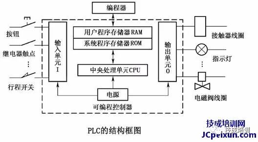
The PLC host consists of the CPU, memory (EPROM, RAM), input/output units, peripheral I/O interfaces, communication interfaces, and power supply. For integrated PLCs, all these components are housed in the same casing.
For modular PLCs, each component is independently packaged, referred to as modules, and connected together via a frame and cables.
All parts within the host are connected via power buses, control buses, address buses, and data buses, and certain external devices are equipped according to the actual control objects to form different PLC control systems.
Common external devices include programmers, printers, EPROM writers, etc. PLCs can be configured with communication modules to communicate with host computers and other PLCs, forming distributed control systems.
Below, each component of the PLC and its functions are introduced to help users further understand the control principles and working processes of PLCs.
(1) CPU
The CPU is the control center of the PLC, coordinating the work of various devices on-site in an orderly manner under its control. The CPU consists of a microprocessor and a controller, capable of performing logical and mathematical operations, coordinating the work of various parts of the control system.
The role of the controller is to ensure that all components of the microprocessor work in an orderly manner, with its basic function being to read and execute instructions from memory.
(2) Memory
PLC is equipped with two types of memory: system memory and user memory. System memory is used to store system management programs, which users cannot access or modify.
User memory is used to store compiled application programs and working data states. The user memory section that stores working data states is also known as the data storage area, which includes input/output data image areas, timer/counter preset values and current values, and buffers for storing intermediate results.
The memory of PLC mainly includes the following types:
(1) Read-Only Memory
(2) Programmable Read-Only Memory
(3) Erasable Programmable Read-Only Memory
(4) Electrically Erasable Programmable Read-Only Memory
(5) Random Access Memory
(3) Input/Output (I/O) Modules
① Digital Input Module
Digital input devices include various switches, buttons, sensors, etc. The input types of PLC can typically be DC, AC, and AC/DC. The power supply for the input circuit can be provided externally, and some can also be supplied internally by the PLC.
② Digital Output Module
The output module converts the control signals output by the CPU executing the user program into signals required to drive specific devices in the production field, thus driving the actions of actuators.
(4) Programmer
The programmer is an important external device for PLC, allowing users to input user programs into the PLC’s user program memory, debug programs, and monitor the execution process. Programmers can be structurally divided into the following three types:
(1) Simple Programmer
(2) Graphical Programmer
(3) General Computer Programmer
(5) Power Supply
The power supply unit converts external power (220V AC power) into internal working voltage. The externally connected power supply is converted into the working power required by the PLC’s internal circuits (DC 5V, ±12V, 24V) through a dedicated switch-mode power supply built into the PLC, and provides 24V DC power for external input components (for input endpoints only). The power supply for driving PLC loads is provided by the user.
(6) Peripheral Interfaces
The peripheral interface circuit is used to connect handheld programmers or other graphical programmers, text displays, and can form the control network of the PLC through peripheral interfaces. PLC can connect to computers via RS-485 interfaces using PC/PPI cables or MPI cards, enabling programming, monitoring, networking, and other functions.
2. Software Composition of PLC
The software of PLC consists of system programs and user programs.
The system program is designed and written by the PLC manufacturer and stored in the PLC’s system memory, which users cannot directly read, write, or modify. The system program generally includes system diagnostic programs, input processing programs, compilation programs, information transfer programs, and monitoring programs.
The user program is the program compiled by users using the PLC’s programming language according to control requirements. In PLC applications, the most important aspect is to write user programs using the PLC’s programming language to achieve control objectives.
Since PLCs are specially developed devices for industrial control, their main users are electrical technicians. To meet their traditional habits and capabilities, the main programming languages of PLCs are relatively simple, easy to understand, and visually oriented compared to computer languages.
1. Graphical Instruction Structure
2. Clear Variable Constants
3. Simplified Program Structure
4. Simplified Application Software Generation Process
5. Enhanced Debugging Tools
3. Basic Working Principle of PLC
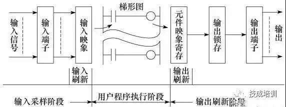
The working mode of PLC scanning is mainly divided into three stages: input sampling stage, user program execution stage, and output refresh stage, as shown in the figure.
1. Input Sampling Stage
In the input sampling stage, the PLC reads all input statuses and data sequentially in a scanning manner and stores them in the corresponding units in the I/O image area. After the input sampling is completed, it transitions to the user program execution and output refresh stages. During these two stages, even if the input status and data change, the statuses and data in the I/O image area will not change.
Therefore, if the input is a pulse signal, the width of that pulse signal must be greater than one scanning cycle to ensure that the input can be read under any circumstances.
2. User Program Execution Stage
In the user program execution stage, the PLC always scans the user program (ladder diagram) in a top-down order. When scanning each ladder diagram, it first scans the control circuits composed of various contacts on the left side of the ladder diagram, performing logical operations on the control circuits composed of contacts in a left-to-right and top-to-bottom order; then, based on the results of the logical operations, it refreshes the status of the corresponding bits in the system RAM storage area or the corresponding bits in the I/O image area, or determines whether to execute the special function instructions specified by the ladder diagram.
During the user program execution process, only the input points’ statuses and data in the I/O image area will not change, while the statuses and data of other output points and soft devices in the I/O image area or system RAM storage area may change, and the execution results of the ladder diagrams above will affect those below that use these coils or data; conversely, the ladder diagrams below can only affect the ladder diagrams above in the next scanning cycle.
3. Output Refresh Stage
After the user program scanning is completed, the PLC enters the output refresh stage. During this period, the CPU refreshes all output latch circuits according to the statuses and data in the I/O image area, and then drives the corresponding external devices through the output circuits. This is when the PLC’s actual output occurs.
Input/Output Lag Phenomenon
From the working process of the PLC, the following conclusions can be drawn:
1. The program is executed in a scanning manner, and there is a theoretical lag in the logical relationship between input/output signals. The longer the scanning cycle, the more severe the lag.
2. The scanning cycle includes not only the time occupied by the three main working stages (input sampling stage, user program execution stage, output refresh stage) but also the time occupied by system management operations. Among them, the execution time of the program is related to the length of the program and the complexity of the instruction operations, while other factors remain relatively constant. The scanning cycle is generally in the nanosecond range.
3. During the nth scanning execution of the program, the input data relied upon is the sampled value X from the sampling stage of that scanning cycle, while the output data is based on the output value Y(n-1) from the previous scan and the current output value Yn; the signal sent to the output terminals is the final result Yn after executing all calculations.
4. Input/output response lag is not only related to the scanning method but also to the arrangement of program design.
Business Cooperation: 010—88379790 ext. 802
Disclaimer: This article is a network reprint, and the copyright belongs to the original author. However, due to numerous reprints, it is impossible to confirm the true original author, so only the source of reprint is indicated. If the videos, images, or text used in this article involve copyright issues, please inform us immediately, and we will confirm the copyright based on the proof materials you provide and pay remuneration according to national standards or delete the content immediately! The content of this article represents the views of the original author and does not represent the views of this public account or its authenticity.