For a while, I found the glow tube quite interesting, and I happened to see a small LCD screen of similar size. So, I created an LCD simulation of a glow tube clock using the LCD to display images (see “AI did half the work, making an LCD simulation glow tube clock” ).
However, the effect was always somewhat lacking. Later, I saw someone sharing a fluorescent tube clock, which looked decent, but the price was significantly cheaper than the glow tube. A glow tube costs around 60 yuan, while the IV-18 fluorescent tube with 8 digits is about 90 yuan, so I decided to make a proper fluorescent tube clock as well.
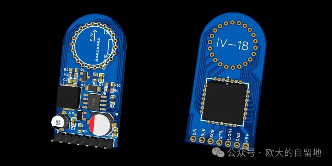
I found some open-source projects on the Lichuang open-source platform for reference and quickly created an IV-18 driver board based on the XL6007 DC-DC boost converter and the HV5812 high-voltage LED driver chip. I successfully tested the soldering at Jialichuang.
I used the code from the Lichuang open-source platform <span>lurt/iv18-vfd</span> to drive the HV5812 with the ESP32-S3, and it worked directly, displaying numbers normally. However, there were some anomalies when displaying certain characters, which should be related to the wiring changes I made to the connections between the IV-18 and HV5812.
HV5812 Driver Board PCB
To keep the area compact and to facilitate future connections with different MCUs, I integrated the XL6007 and HV5812 onto a single PCB and exposed the HV5812 communication pins to the MCU via 2.54mm pin headers for connection.
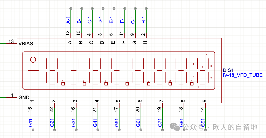
HV5812 and IV-18 Pins
The IV-18 fluorescent tube is a common cathode type, with a total of 17 pins that need to be driven, which are the character selection pins G11-G91 and the segment code selection pins A-H, including the decimal point.
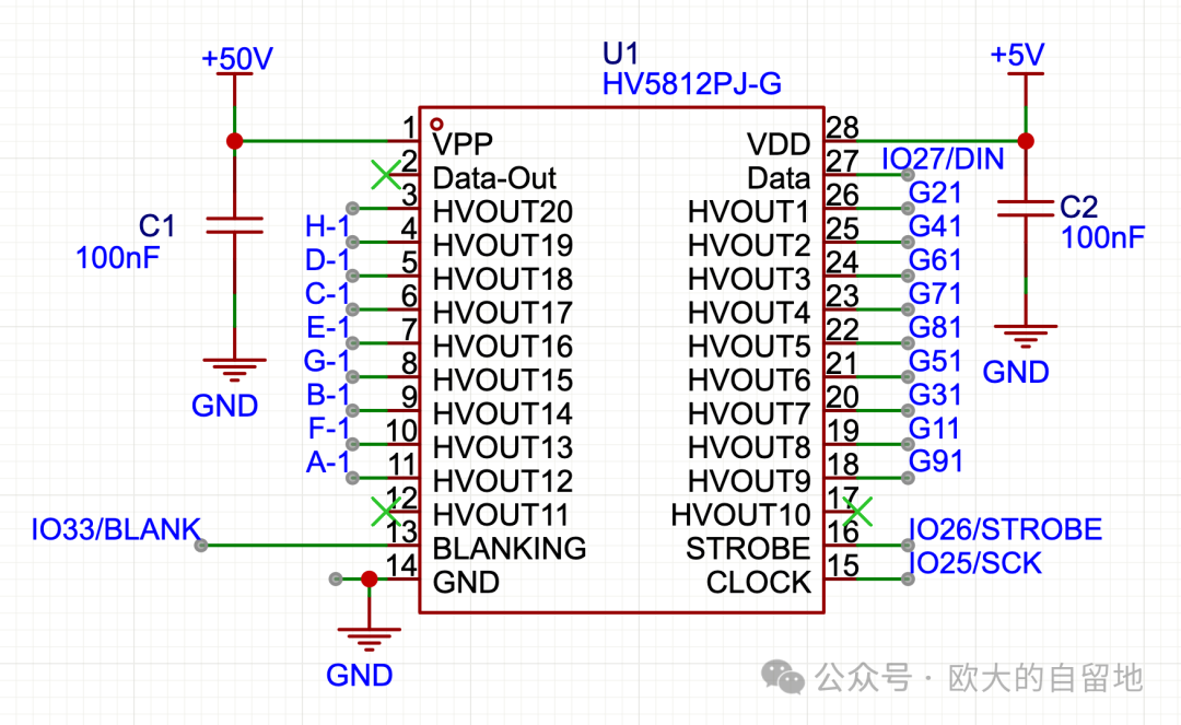
The HV5812 has 20 high-voltage driver pins available. Since the IV-18 only requires 17 pins, there are 3 pins left unused.
HV5812 Data Bit Order
According to the HV5812 data sheet, its shift register is from low to high, meaning the first data sent will go to the high position. Therefore, when writing the driver, all pin states can be represented using a <span>uint32_t</span> and bitwise operations can be used to set the specified pin positions to 1 or 0.
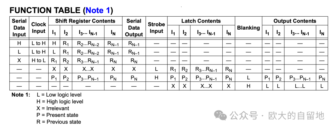
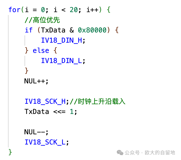
When transmitting data to the HV5812, the 20th bit can be used to determine 1 or 0, and the data can be sent to the HV5812 by looping 20 times to transmit the states of the 20 pins.
The following code is from the <span>lurt/iv18-vfd</span> project, where <span>0x80000</span> corresponds to the state of the 20th bit. After processing 1 bit, the data is left-shifted by 1 bit, and looping 20 times gives the complete HV5812 latch data, with the high bit corresponding to the high pins of the HV5812.
Bitwise Operations + Macros to Generate Character Data
In the original author’s project code, the data codes for numbers and positions are predefined, which means that if the pins used are different from the original project, the displayed characters will not match expectations, or the positions will not be as expected.
As mentioned earlier, the HV5812 driver pins and the states of each bit in the <span>uint32_t</span> can be consistent. This means we can map the corresponding G11-G91 and A-H pins to the HV5812 pin positions, define them using macros, and then use bitwise operations to set the corresponding bits to 1 or 0 during output.
Defining the Pin Correspondence between IV-18 and HV5812
The numbers following the pin definitions here start from 1, corresponding to HVOUT1 to HVOUT20 of the HV5812.
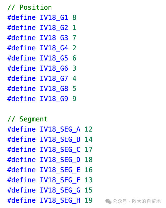
Generating Macros to Set Specific IV-18 Pins to 1
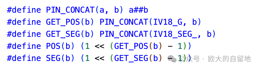
By using macros for concatenation, we can use <span>POS(1)</span> or <span>SEG(D)</span> macros to obtain the data that sets the corresponding positions of G11 or segment D to 1.
Generating Character Data
With the above macros, generating character data becomes straightforward. We can directly use the <span>SEG</span> macro to perform a bitwise OR operation on all the data that sets the corresponding segments to 1 based on the segment code display rules.
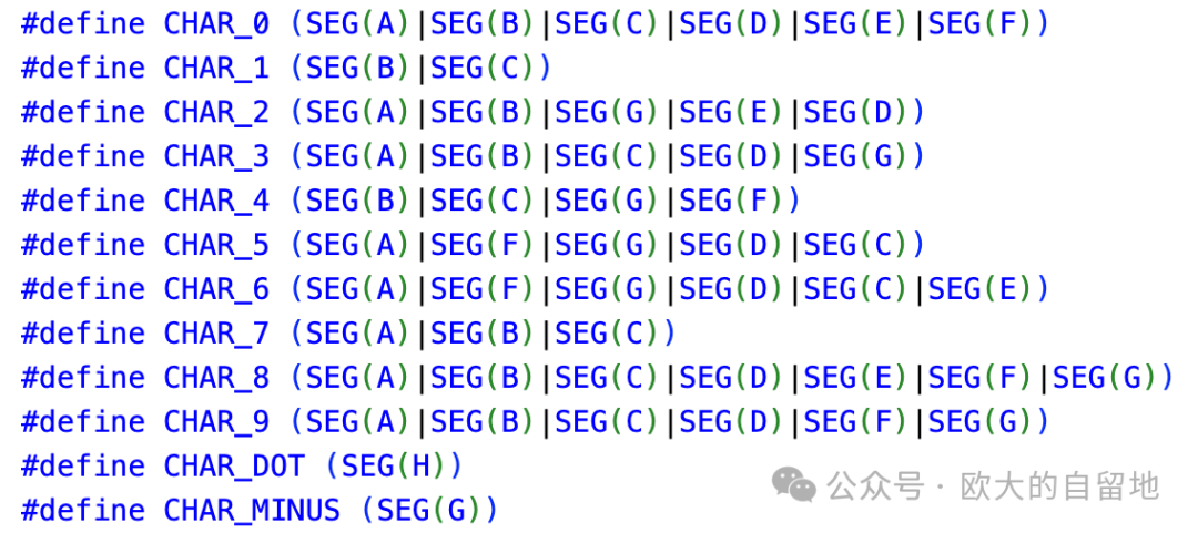
This way, when the pins are changed later, there is no need to modify the character data code, as it will be automatically generated from the previous pin macro definitions.
Generating Character and Position Data Tables
To facilitate displaying numbers later, we can generate an index table for the numbers and their corresponding position data and write a <span>GET_DATA</span> macro to quickly generate the data for displaying a specified character at a specified position. For example, using <span>GET_DATA(1, 8)</span> will generate the driver data to display the number 8 at position 1.
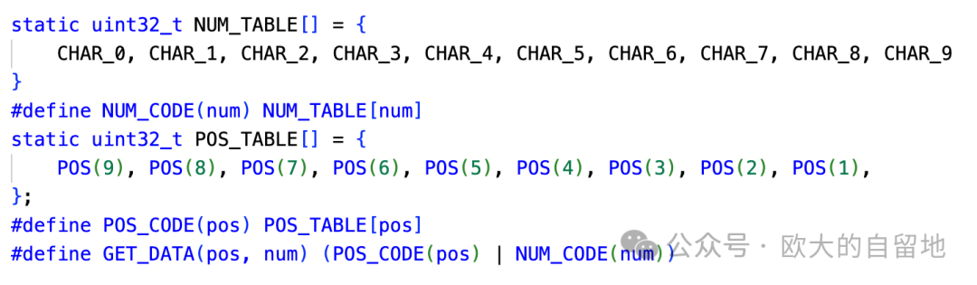
Note that the <span>POS_TABLE</span> is defined in reverse because, in the IV-18, the 9th position is the highest bit.
Completing the Driver
At this point, we have completed the use of bitwise operations and macros to generate the data required for driving the IV-18 with the HV5812. Furthermore, when there are changes in pin definitions, there is no need to modify the subsequent display code; we only need to modify the pin definitions, and the related data will be updated automatically.
Conclusion
Driving the IV-18 is simpler than expected; it only requires outputting high levels to the corresponding segment code pins. Perhaps because the current changes in the IV-18 are not very drastic, the XL6007 circuit can work adequately without much fuss.
To enable the display of letters in the future, spending some time making the HV5812 + IV-18 driver configurable is worthwhile. Although it only has 7 segment codes, it can still display commonly used letters.
Thanks again to the <span>lurt/iv18-vfd</span> open-source project, including the PCB and driver code.
References
-
https://oshwhub.com/lurt/iv18-vfd
-
https://www.opledtw.com/zh-hant/blog/7-segment-16-segment-display-numeral-alphabet-explained/
-
https://blog.csdn.net/fairen/article/details/108843110
Follow the Public Account for Updates
If this article has helped you, please follow, like, share, or repost. Thank you very much 😃.
Other DIY Projects
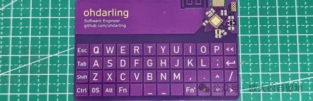
Remember that credit card-sized pure PCB keyboard? Now it has firmware!
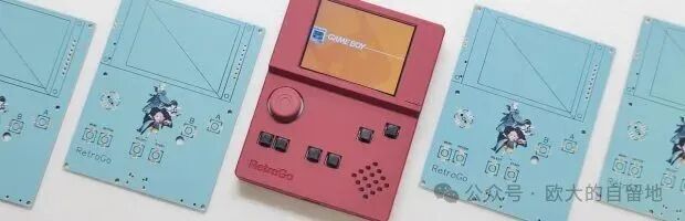
Costing 60 yuan, using ESP32-S3 to make an open-source game console that can play FC/NES, GameBoy, and has a custom colored PCB.
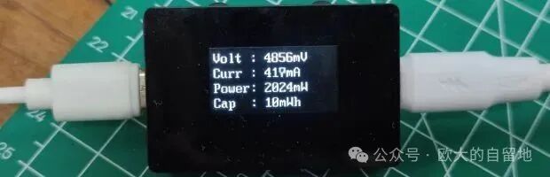
DIY USB ammeter tutorial, diving into hardware design, firmware development, and appearance modeling.
Historical Articles
-
Using C language bitwise operations to write a simple and efficient microcontroller OLED framebuffer driver.
-
Hands-on experience with the fully integrated RISC-V IDE – MounRiver Studio II.
-
ESP32 and Arduino enthusiasts must not miss this online simulation website.
-
AI did half the work, making an LCD simulation glow tube clock.
-
Can AI programming be used in embedded development? Experience with Manus writing ESP32 firmware.
-
How powerful is the IP KVM that raised 5 million dollars in crowdfunding? JetKVM unboxing and trial.
-
Current 15uA for a year of battery life? Attempting low-power applications with CH32V003.
-
Remember that credit card-sized pure PCB keyboard? Now it has firmware!
-
Recreating Xiao Zhi AI, building an Arduino + ESP-SR + ESP-TTS development environment with ESP32-S3, and documenting the pitfalls.
-
How much does it cost to sell for 25 yuan? Disassembling a 500-in-1 game console.
-
Here it comes! Running a RISC-V emulator on the ESP32-S3 microcontroller to run Linux, this time it only takes 8 seconds to boot.
-
No-code DIY all-in-one air monitoring station AirCube, which can also connect to Home Assistant.
-
Fully open-source! DIY USB ammeter tutorial using a microcontroller costing 0.7 yuan, diving into hardware design, firmware development, and appearance modeling.