In the computer networking architecture, the network layer (the third layer of the OSI model) is the core for achieving data transmission across networks, with the primary goal of providing end-to-end logical paths for hosts in different networks, and forwarding packets from the source host to the destination host through routing. The following sections will detail the network layer from aspects such as core functions, core protocols, routing mechanisms, key concepts, and Linux practices.
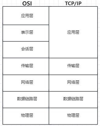
1. Core Functions of the Network Layer
The functions of the network layer revolve around “data transmission across networks” and mainly include:
1. IP Addressing: Assigning a unique logical address (IP address) to hosts in the network to identify the network location of the host (similar to a “house number”).2. Routing: Selecting the optimal transmission path from the source host to the destination host in an interconnected network composed of multiple networks (subnets) (achieved through routing tables and routing protocols).3. Packet Forwarding: Routers forward received packets from one network interface to another based on the routing table (achieving “inter-segment hopping”).4. Congestion Control: When network load is too high, controlling the packet transmission rate or dropping some packets to prevent network paralysis (supported by some routing protocols).5. Fragmentation and Reassembly: When the packet size exceeds the MTU (Maximum Transmission Unit) of the underlying link, it is split into smaller fragments and reassembled upon reaching the destination (implemented by the IP protocol).
2. Core Protocols of the Network Layer
The core protocol of the network layer is based on the IP protocol, supplemented by other auxiliary protocols to achieve functional collaboration. Common protocols include:
1. IP Protocol (Internet Protocol)
The IP protocol is the “cornerstone” of the network layer, responsible for defining the format and transmission rules of packets, divided into IPv4 and IPv6 versions.
-
IPv4 Protocol is the most widely used version, with an address length of 32 bits (4 bytes), formatted as “dotted decimal” (e.g.,
<span>192.168.1.1</span>), with a total address count of about 4.3 billion (exhausted). - IPv4 Packet Structure (fixed header of 20 bytes, optional fields up to 40 bytes):
Field Length (bits) Function Version 4 Identifies IP version (4=IPv4, 6=IPv6) Header Length 4 Indicates IP header size (in 32-bit words, minimum value 5=20 bytes) Type of Service 8 Indicates the priority of the packet (e.g., delay, throughput requirements) Total Length 16 Total size of the packet (header + data, maximum value 65535 bytes) Identification 16 Identifies the same original packet during fragmentation (basis for reassembly) Flags 3 Controls fragmentation (DF=1 prohibits fragmentation, MF=1 indicates more fragments follow) Fragment Offset 13 Position of the fragment in the original packet (in 8-byte units, used for reassembly) Time to Live (TTL) 8 Limits the lifetime of the packet (decreases by 1 for each router passed, discarded at 0 to prevent loops) Protocol 8 Indicates the upper layer protocol (e.g., 6=TCP, 17=UDP, 1=ICMP) Header Checksum 16 Checks if the header is damaged (only checks the header, not including data) Source IP Address 32 Sender’s IP address Destination IP Address 32 Receiver’s IP address Options (optional) Variable Used for debugging, security, and other extended functions (e.g., record route, timestamp) -
IPv6 Protocol was designed to address the exhaustion of IPv4 addresses, with an address length of 128 bits (16 bytes), formatted as “colon-separated hexadecimal” (e.g.,
<span>2001:0db8:85a3:0000:0000:8a2e:0370:7334</span>), with a total address count of about 3.4×10³⁸ (almost infinite). - Simplified header (fixed 40 bytes, removed checksum and other fields to improve forwarding efficiency);
- Built-in IPsec security mechanism;
- Supports auto-configuration (addresses can be assigned without DHCP);
- Eliminates fragmentation (determined by the sender in advance based on MTU).
- Improvements in IPv6:
2. ICMP Protocol (Internet Control Message Protocol)
ICMP is the “auxiliary protocol” of the IP protocol, used for network diagnostics and control, not transmitting user data but only control information (e.g., error reports, status queries).
- Common applications:
<span>ping</span>command: detects host connectivity through ICMP Echo Request (request) and Echo Reply (response);<span>traceroute</span>command: traces the route of packets from source to destination by setting different TTL values (each hop returns a “TTL expired” error).
3. ARP Protocol (Address Resolution Protocol)
Although ARP belongs to the data link layer, it is closely related to the network layer: it is used to map IP addresses to MAC addresses (since the data link layer only recognizes MAC addresses).
- Workflow: The host sends an “ARP request” broadcast (asking “Who has IP address X? Please reply with MAC”), the target host replies with an “ARP response” (informing its MAC address), and the sender caches the mapping (ARP cache).
3. Routing Mechanism
Routing is the core function of the network layer, referring to “the path selection for packets from source to destination,” implemented by routers (or hosts) through routing tables.
1. Routing Table
The routing table is a “set of path rules” stored in routers (or hosts), with each rule containing:
- Destination Network: The network where the target host is located (e.g.,
<span>192.168.2.0</span>); - Subnet Mask: Used to determine which network the target IP belongs to (e.g.,
<span>255.255.255.0</span>); - Gateway (Next Hop): The IP of the next router to which the packet needs to be forwarded (e.g.,
<span>192.168.1.1</span>); - Interface: Which network interface on the local machine to send from (e.g.,
<span>eth0</span>); - Metric: Path priority (the smaller the value, the higher the priority, such as hop count, bandwidth).
For example, in Linux, the routing table can be viewed using <span>route -n</span>:
Kernel IP routing tableDestination Gateway Genmask Flags Metric Ref Use Iface0.0.0.0 192.168.1.1 0.0.0.0 UG 100 0 0 eth0192.168.1.0 0.0.0.0 255.255.255.0 U 100 0 0 eth0<span>0.0.0.0: Default route (all unmatched IPs go through this path);</span>
<span>192.168.1.0: Directly connected network (no gateway needed, sent directly through eth0).</span>
2. Routing Types
-
Static Routing: Routing rules manually configured by the administrator (suitable for small networks, simple to configure but high maintenance cost). For example, adding a static route in Linux:
<span>route add -net 192.168.3.0 netmask 255.255.255.0 gw 192.168.1.2</span>(the target network<span>192.168.3.0</span>needs to be forwarded through the gateway<span>192.168.1.2</span>). -
Dynamic Routing: Routing rules automatically learned and updated by routers through routing protocols (suitable for medium to large networks, adaptable to network changes).
3. Dynamic Routing Protocols
Dynamic routing protocols are divided into Interior Gateway Protocols (IGP) and Exterior Gateway Protocols (EGP):
| Protocol Type | Representative Protocol | Applicable Scenarios | Core Principle |
|---|---|---|---|
| IGP | RIP (Routing Information Protocol) | Small networks (≤15 hops) | Distance vector algorithm: Measures paths by “hop count” (each router passed counts as 1 hop), periodically broadcasts routing tables. |
| IGP | OSPF (Open Shortest Path First) | Medium to large networks | Link state algorithm: Routers exchange “link state information” (such as bandwidth, delay) and calculate the shortest path using Dijkstra’s algorithm. |
| EGP | BGP (Border Gateway Protocol) | Between different autonomous systems (AS) | Path vector algorithm: Selects routes based on “autonomous system paths” (avoiding loops), focusing on policy rather than shortest path. |
- Autonomous System (AS): A collection of networks managed by a single entity (such as a company or an operator’s network), each AS has a unique number (1-65535).
4. Key Concepts of the Network Layer
1. Subnet and Subnet Mask
- Subnet: Dividing a large network into multiple smaller networks (reducing broadcast domains and improving security);
- Subnet Mask: Identifies network bits with “1” and host bits with “0”; performing a bitwise AND operation with the IP address can yield the network address. For example: IP
<span>192.168.1.100</span>+ Subnet Mask<span>255.255.255.0</span>→ Network Address<span>192.168.1.0</span>.
2. CIDR (Classless Inter-Domain Routing) is a scheme to simplify IP address allocation, formatted as “IP / prefix length” (e.g., <span>192.168.1.0/24</span>, where the prefix length of 24 indicates that the first 24 bits are network bits, equivalent to the subnet mask <span>255.255.255.0</span>).
- Function: Reduces routing table entries (aggregating multiple subnets into a single routing entry).
3. TTL (Time to Live)
IP header field that limits the maximum number of hops a packet can take in the network (default 64 or 128). TTL decreases by 1 for each router passed; if TTL=0, the router discards the packet and returns an ICMP “timeout” error (to prevent infinite loops).
5. Network Layer Configuration and Tools in Linux
In Linux, the following tools can be used to manage network layer configuration:
1. IP Address Configuration
<span>ip addr</span>: View / configure IP addresses (replacing<span>ifconfig</span>). For example:<span>ip addr add 192.168.1.10/24 dev eth0</span>(adds an IP to<span>eth0</span>).
2. Routing Management
<span>ip route</span>: View / configure routing tables (replacing<span>route</span>). For example:<span>ip route add default via 192.168.1.1</span>(adds a default gateway).
3. Diagnostic Tools
<span>ping</span>: Detects host connectivity (based on ICMP);<span>traceroute</span>: Traces the path of packets (based on TTL and ICMP);<span>ip route get targetIP</span>: Views the routing path for a specified IP (e.g.,<span>ip route get 8.8.8.8</span>).
Conclusion
The network layer is the core for achieving “inter-network communication,” defining addresses and packet formats through the IP protocol, selecting transmission paths through routing mechanisms, and collaborating with protocols such as ICMP and ARP. In Linux, network layer parameters can be configured using tools like <span>ip</span> and <span>route</span>, and network issues can be diagnosed using tools like <span>ping</span> and <span>traceroute</span>. Understanding the workings of the network layer is fundamental to mastering Linux network configuration and troubleshooting.
The following chapters will continue to elaborate on protocols such as IPV4, IPV6, ICMP, and ARP.If you find this article helpful, you can support it with a donation!