ver0.1
Introduction
In previous articles, we discussed the system architecture of power management based on the ARM architecture, covering the core nodes and mechanisms related to hardware power management. This laid the foundation for introducing the software architecture of power management. Imagine, as a developer, especially one aspiring to advance, one day your manager assigns you a task: optimizing software to ensure that the SOC enters the Suspend state with current consumption not meeting standards (power consumption not meeting standards). How should you approach this task? Any design proposal must theoretically pass muster, but discussing software without hardware is like building a tower on sand, lacking a foundation. With the previous hardware foundation, this article shifts focus back to the software layer to continue examining ARM’s power management, primarily discussing the important lever of power management software: power states. Before reading this article, I hope everyone will read our previous articles to grasp some basics and get a feel for the topic:
(1)[V-02] Basics of Virtualization – CPU Architecture (based on AArch64)
(2)[A-03] ARMv8/ARMv9 – Multi-level Cache Architecture
(3)[A-21] ARMv8/v9 – Overview of SMMU System Architecture and Functions
(4)[A-25] ARMv8/v9 – System Architecture of GIC (Hardware Foundation of Interrupts)
(5)[A-38] ARMv8/v9 – Generic Timer System Architecture
(6)[A-41] ARMv9/v8 – Power Management System Architecture
(7)[A-42] ARMv9/v8 – Overview of Power Management Working Principles (SCP Service Overview)
(8)[A-43] ARMv9/v8 – Introduction to Power Control Framework (PCF)
(9)[A-0x2c] ARMv9/v8 – Power Management Domains (Voltage Domain/Power Domain)
(10)[A-45] ARMv9/v8 – Power Modes
Body
1.1 Background
1.1.1 Classification of Power Management Software
We are finally going to tackle the software management part of PCSA. First, let’s look at a high-level software architecture diagram:
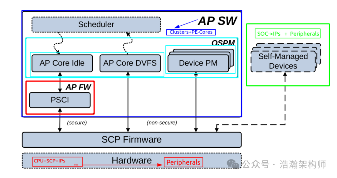
Figure 1-1 Simplified power management software stack
Starting with hardware, a complete hardware product includes an SOC along with necessary peripherals. In terms of power management software, it can be broadly categorized into three types:
(1) The first category is peripherals: If a peripheral does not receive direct power from the SOC, such as a hot-swappable display that is independently powered, it can manage itself and essentially decouple from the SCP. It can communicate with the SOC’s AON module or directly with the corresponding SOC IP at the protocol level. For example, the HDMI, DP, eDP of the display subsystem can manage their own power without recognizing the SCP as the authority.
(2) The second category is IP on the SOC: This type of IP accepts management from the SCP but may not want to accept control from the CPU. Even when the CPU is in sleep mode, it can still perform some tasks. These devices can send messages directly to the sleeping CPU through events or interrupts when needed. If these devices can completely decouple from the CPU and do not require any driver code configuration, they can be considered a separate category, although such IPs are relatively rare.
(3) The third category is SOC IP: This type of IP accepts management from the SCP and also accepts configuration from drivers running on the CPU, so we categorize them together. The prominent feature of this category is that general operating systems will customize a framework for them, and they just need to fill in the blanks. This framework is OSPM, which essentially opens a door for software to adjust the state of the IP it covers based on its own loading or the SOC’s state. Among these IPs, the most notable is the CPU.
The above classification is purely personal customization. You can further understand it by considering the hierarchical dependencies of power domains in Figure 1-2, which we will not elaborate on here. If you are not familiar with power domains and their operational modes, I recommend reading the previous articles.
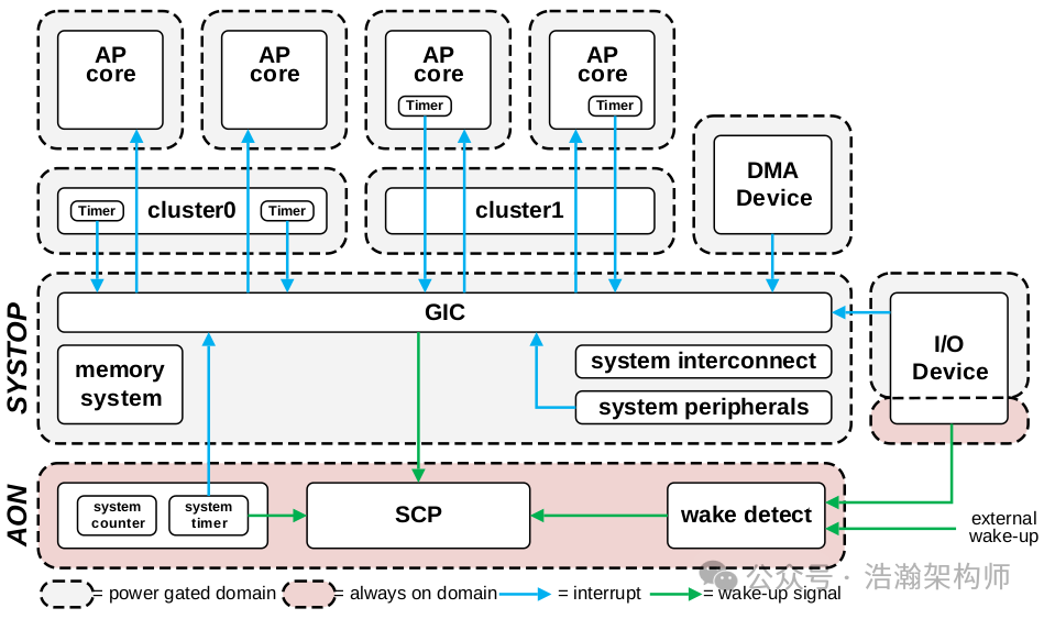
Figure 1-2 Example power domain hierarchy
1.1.2 Power Management Software Content
From Figure 1-1, we can see that OSPM management work is mainly divided into two major parts: PE-Cores and other devices.
PE-Cores
Let’s first focus on the management content of OSPM for PE-Cores:
OSPM for AP cores can be broadly classified into idle management and dynamic voltage and frequency scaling (DVFS) frameworks.
Idle Management
The general principle for idle management is that when no threads are scheduled onto an AP core, the OSPM places that core into a clock gated, retention, or fully powered-off state. A powered-off core remains available to the OS for scheduling and can be woken by interrupts.
An alternative technique, commonly known as hot-plug, might also be implemented. In this case, AP cores are removed from the pool available to the OS for scheduling. With this technique, cores are powered-off and all interrupts and software threads are migrated to other cores. This technique can be used either in proportion to demand or in cases where compute capacity must be limited due to power or thermal constraints.
DVFS Management
DVFS provides a mechanism for managing the power-performance envelope. From an energy-performance perspective, a wide range of OSPM policies are used to determine the required operating level. The objective is to meet performance requirements when demanded, but otherwise minimize energy consumption. Thermal management frameworks can impact the requested operating level by limiting the maximum performance allowed.
From the manual’s description, we can see that OSPM’s management of PE-Cores is mainly divided into two aspects: IDLE and DVFS.
(1) IDLE management primarily aims to put the PE-Core into a low-power state when there is nothing to do, with the goal of saving power. When there is work to do, it should be able to quickly return to normal working state, and the smaller the delay in this process, the better.
(2) DVFS mainly starts from the performance perspective, integrating software load and thermal control to allow PE-Cores to operate at the most suitable frequency for the current situation.
Both IDLE management and DVFS management rely on interventions from modules outside of OSPM, mainly involving computational scheduling, which will be a key focus of our subsequent research.
Devices
Let’s first refer to the manual’s description:
The power management of devices encompasses both device-specific aspects in drivers and higher-level frameworks.
At a high level, devices can be said to have two types of behavior and capability:
• OS managed: In this case, a device is entirely dependent on the OSPM and any driver to ensure the provision of system resources for its operation.
• Self-managed: Some devices will act as agents that make direct requests to the SCP for a subset of their power management functions. In some cases, this can be all power management functions, and such devices are described as fully self-managed. Partially self-managed devices directly request SCP for some functions but rely on OSPM for the remainder.
Most devices in the system are typically OS managed. The degree of power management required varies depending on the device.
Many basic peripherals are typically in parts of the system that are powered-on whenever the system is running. Some of these peripherals might also be clocked by default and therefore require no explicit power or clock management.
Other peripherals will require clocks to be enabled, and more complex devices can also require specific power domains to be powered-on. When a power management action is needed, the driver software typically expresses this dependency through an abstraction to the OSPM. The OSPM then requests the SCP to perform any actions to satisfy these dependencies using the SCP software interface.
The above lengthy description can be categorized according to the classification principles mentioned in previous sections:
(1) Completely decoupled from OSPM, partially decoupled from OSPM, and strongly coupled with OSPM. Therefore, when your boss asks you to optimize power, you need to first check which part it belongs to.
(2) Some peripherals require the SOC to provide necessary hardware signal support to work, and these signals also need to operate in special power modes, which is also part of power management work.
(3) Most of the time, chip manufacturers will debug the interdependencies of power working modes between internal devices of the SOC at both the software and hardware levels before selling them, so you can use them with confidence. (There are also cases where debugging is not done well, and if you encounter unreliable integrators, it can be quite a story.)
1.2 Power States
Let’s set aside device power management and DVFS power management for now. In this article, we will first clarify the power states of PE-Cores, as the CPU is currently the module with the most and most complex power modes in an SOC. ARM has specifically created a PSCI framework for managing their power states. Understanding the power states of the CPU will provide a roadmap for studying the power states of other IPs on the bus.
1.2.1 Concept of Power States
First, let’s look at the description in the manual:
A power state represents a software-visible abstraction of available hardware power modes.
A power state is defined according to wake capability, loss of context, and power consumption. The selection of a power state by software is typically made using an idle residency prediction. This prediction is used to make a state selection based on target residences, derived from energy break-even times, for each available state. Wake latency requirements, which must not be violated, might then limit the choice to a shallower state.
The power state selected by software sets constraints on which power modes can be selected.
Combining the manual’s description, we can summarize the power states as follows:
(1) Power states are an abstraction of hardware power modes, making modes visible and operable at the software level. In other words, power states are a software-level concept within the power management system.
(2) The definition of power states must consider three factors: wake capability, context retention, and power consumption.
• Wake capability includes how to wake (interrupt or EVENT) and the wake delay.
• Context data mainly includes registers, cache, and data in external memory (DDR), as shown in Figure 1-3.
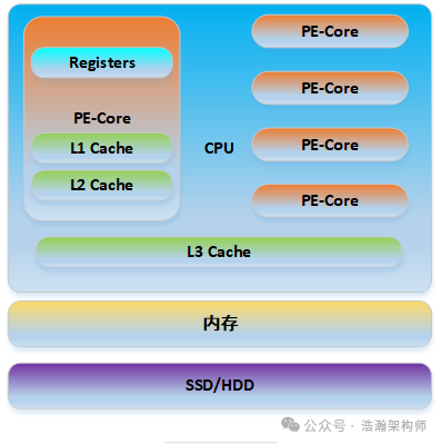
Figure 1-3 High-Level Memory SubSystem
(3) Power consumption is not about saving energy at all costs, but rather a dynamic balance between energy efficiency and response speed, achieving an optimal energy efficiency ratio. This is relatively easy to understand; think about your phone’s performance while gaming, listening to music, or in standby mode.
1.2.2 Core Power States
Let’s first look at how many states the PE Core has:
RUN
The core is powered-on and running code.
IDLE_STANDBY
The core is in WFI state. Full context is retained and no software state saving or restoration is required. Execution automatically resumes after any interrupt or external debug request. Debug registers are externally accessible.
IDLE_RETENTION
The core is in WFI state. Full context is retained and no software state saving or restoration is required. Execution automatically resumes after any interrupt or external debug request. Debug registers are not externally accessible.
SLEEP
The core is powered-off, but hardware will wake the core autonomously, for example, on receiving a wake-up interrupt from the GIC. No context is retained, so state must be explicitly saved. A woken core starts at the reset vector, and then hardware-specific software will restore state.
OFF
The core is powered-off and is not required to be woken by interrupts. The only way to wake the core is by explicitly requesting it to be powered-on by the power controller, for example, from system software running on another core, or an external source such as a power-on reset. This state can be used when the system software explicitly decides to remove the core from active service, giving the hardware the opportunity for more aggressive power saving. No core context is retained.
We will not elaborate too much on the meanings of each state, as they are similar to Power Modes. Here we summarize the characteristics of these states; in fact, OSPM software selects states based on the following characteristics:
(1) From RUN to OFF, power consumption increases while the loss of running context becomes more severe.
(2) From OFF to RUN, the efficiency of restoring work increases, and the retention of running context improves.
1.2.3 Cluster Power States
The upper system architecture circuit of the PE-Core is the DSU, as shown in Figure 1-4:
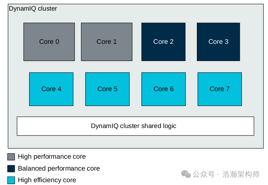
Figure 1-4 DSU example
As a container for PE-Cores, the DSU also has its own independent power states:
This document defines the following AP cluster power states.
RUN
The cluster is powered-on and can support any core moving to any power state.
SLEEP_RETENTION
The cluster is powered-off, but able to wake on receiving a wake-capable interrupt. At least one core in the cluster is in SLEEP, while other cores are in SLEEP or OFF.
The cluster shared cache content is retained.
Before a core in the cluster can move to a higher power state, the cluster must first move to RUN.
SLEEP
The cluster is powered-off, but able to wake on receiving a wake-capable interrupt. At least one core in the cluster is in SLEEP, while other cores are in SLEEP or OFF.
The cluster shared cache content is not retained.
Before a core in the cluster can move to a higher power state, the cluster must first move to RUN.
OFF
The cluster is powered-off and will not wake on receiving an interrupt. All cores in the cluster are in OFF.
The cluster shared cache content is not retained.
Before a core in the cluster can move to a higher power state, the cluster must first be moved to an appropriate higher power state.
This part will not be discussed in detail; you can refer to the power states of PE-Cores. It is important to note that the power states of the cluster are dependent on the power states of the PE-Cores.
1.2.4 Other IP Power States
In addition to PE-Cores and clusters, other IPs and power domains on the SOC also have their own power states:
RUN
The device is powered-on and can perform its operations. Driver-specific actions might, however, be needed to enable clocks and other capabilities.
OFF
The device is powered-off. The only way to wake the device is by explicitly requesting it to be powered-on. Typically, the driver software will express this dependency through an abstraction to the OSPM. The OSPM can request the SCP to perform any required actions.
ARM’s manual only lists two types, but in reality, there can be differences in power states based on the implementation technology of different IPs (meaning there can be power states other than RUN and OFF). The selection of these power states mainly depends on the interaction between the IP driver or firmware within the IP and the SCP. (Currently, we are optimizing the GPU, focusing on clk and Regulator as two key levers.)
1.2.5 SoC Power States
Let’s look at the states of the SOC:
RUN
The SoC system is available and can support any processor cluster moving to any power state. Devices can also move to any power state.
At least one AP core in the system is in RUN or SLEEP.
The GIC is on and system memory is available.
SLEEP
The SoC system is unavailable and can be powered-off, but always-on domain wake capabilities including the system counter and wake-up timer remain powered-on. The SoC can self-wake using the wake-up timer. It can also wake in response to any system-specific always-on domain wake event.
At least one of the processor clusters must be in SLEEP, and remaining clusters must be in SLEEP or OFF. As the GIC is powered-off, the only interrupts able to wake processors are always-on domain wake events.
DEEPSLEEP
The SoC is powered-off, including the system counter and wake-up timer. The system is unable to self-wake. It can only wake in response to an external event, such as a power-on reset.
External DRAM memory is held in a retention state by implementation-specific means.
OFF
The SoC is powered-off, including the system counter and wake-up timer. The system is unable to self-wake. It can only wake in response to an external event, such as a power-on reset.
External DRAM memory is not retained. Hibernation of state to non-volatile memory might be used, but this is beyond the scope of this document.
The above is an excerpt of the SOC power states from the manual. The specific states implemented by the SOC depend on the implementations of various chip manufacturers. We will not elaborate on this further; the main point is to grasp that the SOC’s power states are also dependent on the power states of the integrated CPU and other IPs.
1.2.6 Power State Hierarchy
The previous section mentioned that the power states of various power domains in the SOC have interdependencies, as shown in Figure 1-5:
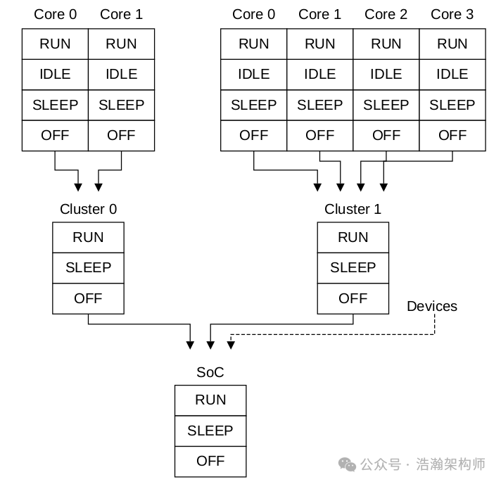
Figure 1-5 Example power state hierarchy
The above is an example of the inheritance relationship of SOC power states. We summarize: the power state of the parent node’s power domain cannot be deeper than the power state of the child node’s power domain.
Here are some examples:
(1) As long as one terminal power domain in the SOC is in the RUN state, then all power domain components along this link cannot be in any state other than RUN (Sleep and OFF).
(2) When the SOC is in the OFF state, all other power domains must also be in the OFF state.
(3) When Core 0 is in IDLE state, Cluster 0 can be RUN, but not Sleep.
(4) When Cluster 0 and Cluster 1 are in Sleep state, the SOC cannot be in OFF state.
1.3 Relationship between Power States and Power Modes
After discussing the basic concepts of power states, let’s revisit the mapping relationship between Power States and Power Modes, starting with their differences:
1.3.1 Differences between Power States and Power Modes
From the previous sections, we understand that Power States are for software use, while Power Modes are for hardware use. So what are their differences?
Distinction of Power States from Power Modes
It is important to make a clear distinction between the power modes supported by the hardware and the power state view of software. The primary reason for this distinction is that there is no direct mapping between these two views. In summary:
• Not all hardware power modes are software visible.
• Power modes are differentiated based on hardware techniques, whereas the considerations for defining a software power state are wake capability and loss of context.
• A single power state can map to one or more power modes, with equivalent context and wake properties, where the power modes are chosen autonomously by the power control system. Autonomous modes must preserve the properties of the selected power state without a perceived impact on latency on exit from the state.
• The power mode selected can be shallower than the power state constraints allow, but not deeper.
We summarize the manual’s description as follows:
(1) First, not all power modes of the power domain are visible to software.
(2) A power state can map to multiple power modes.
(3) The core factors considered by upper-level software when selecting power states are the degree of context retention and wake speed.
(4) Under specific power states, the depth of hardware mode selection cannot exceed the depth of the power state. For example, when the power state is RUN, the power modes can only be ON, not FUNC_RET (Functional Retention), as shown in Figure 1-6.
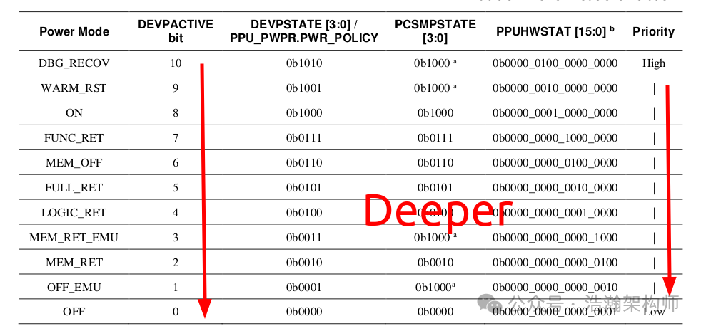
Figure 1-6 Power mode enumeration
1.3.2 Mapping Relationship between Power States and Power Modes
In the previous section, we learned that Power States and Power Modes have a mapping relationship. In this section, we will illustrate this with the example of the DSU:
The DynamIQ ™ Shared Unit-120 (DSU-120) supports different power domains. You do not need to implement all power domains. The number and type of domains that are implemented depend on the choices made by the System on Chip (SoC) implementer. Each of the L3 cache slices, cores, and complexes can be placed in their own separate power domain. As the number of these components can vary depending on implementation, therefore the total number of power domains can also vary.
The DSU-120 specification states that this circuit unit is filled with many Power Domains, as shown in Figure 1-7:
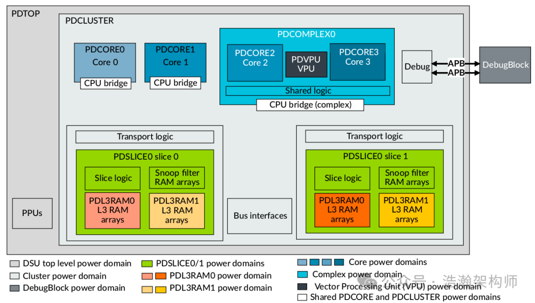
Figure 1-7 DSU-120 power domains
What power domains do these support? As shown in Figure 1-8:
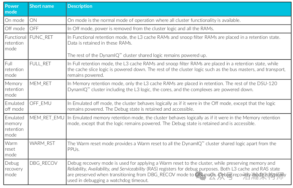
Figure 1-8 DSU-120 DynamIQ ™ cluster power modes
Depending on the internal implementation of the DSU, these power modes also have different migration states, as shown in Figure 1-9:
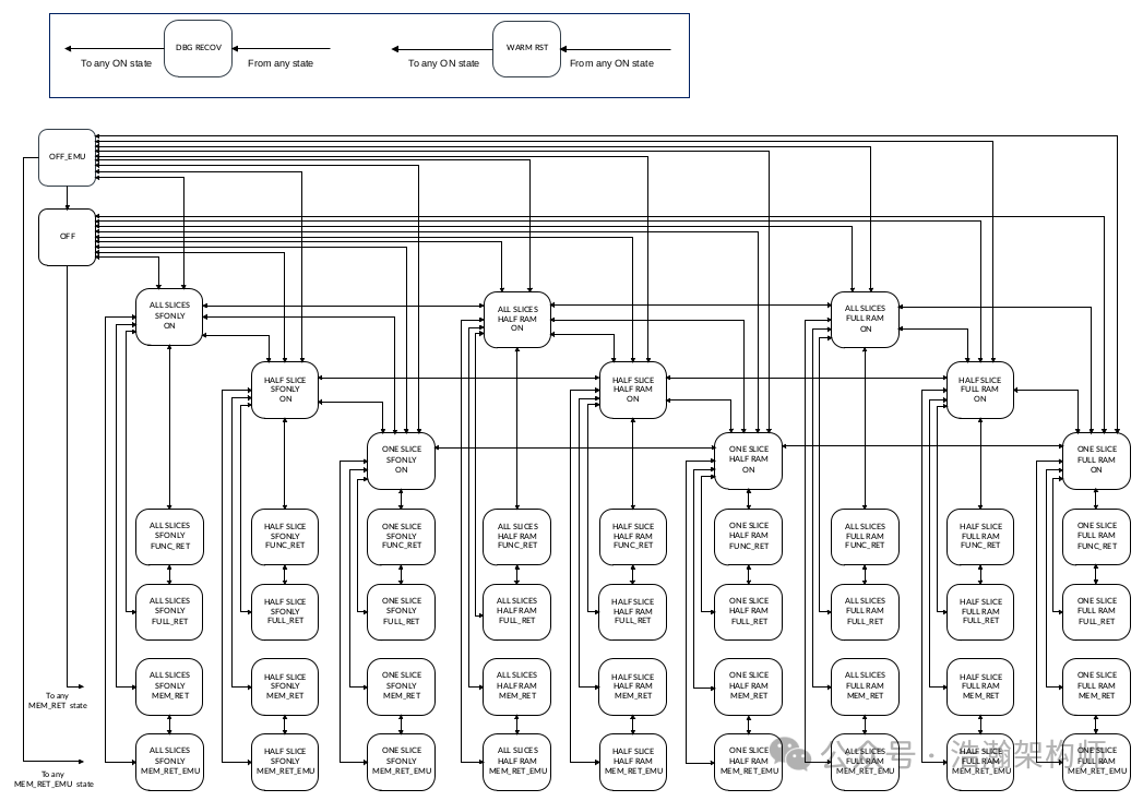
Figure 1-9 DSU-120 DynamIQ ™ cluster PPU mode transitions
The above actually connects to the previous article where we introduced power modes. For those who are struggling to keep up, I recommend reading the earlier articles. Now let’s look at the mapping relationship between the cluster’s power states and power modes, as shown in Figure 1-10:
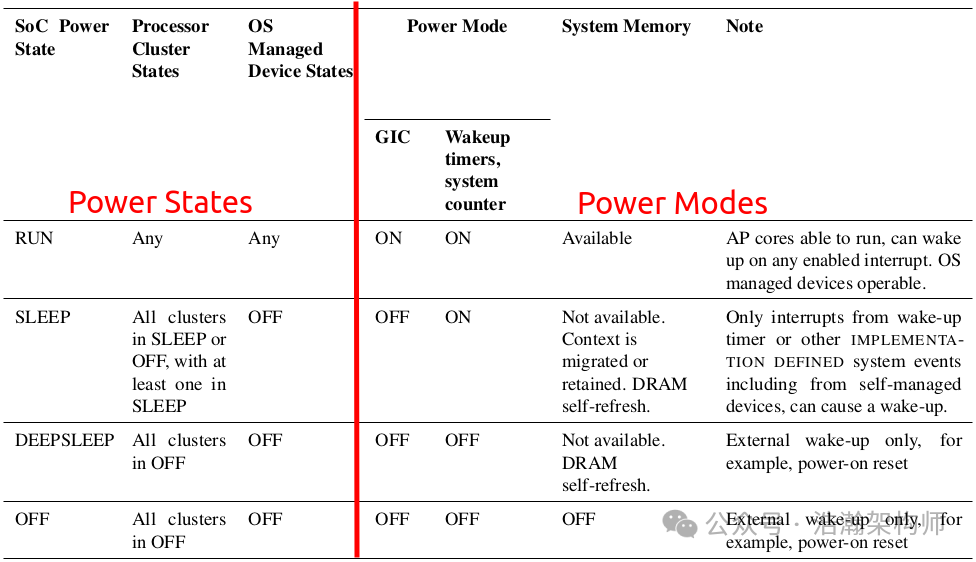
Figure 1-10 DynamIQ Shared Unit: cluster power states mapping to modes
In the above figure, from the perspective of DSU Power States, the mapping of power states and modes is illustrated. When the cluster is RUN:
(1) PE-Cores can be in any state.
(2) The power mode of the DSU must be ON.
(3) L3 Cache (if implemented) can be in any of ON, RET, OFF.
The mapping relationship above also complies with the constraints of the previous section regarding the mapping of power modes and states. You can deduce the SOC mapping relationship shown in Figure 1-11; we will not elaborate on this further.
Figure 1-11 SoC power states
Conclusion
In this article, we categorized devices on the SOC based on whether they accept OSPM intervention into three types, then introduced the content of software power management and key levers: Clock, Regulator, and Power States. We then delved into the basic concepts and classifications of power states, and finally discussed the relationship between power states and power modes, including their distinctions and mapping relationships. This article serves as an important foundation for our research on the power management architecture under the ARM system. Having crossed this threshold, we are about to enter the world of power management software. Recently, I have been analyzing the black screen issues in mass production projects, and most of the problems can be related to power management, especially under virtualization architectures. Understanding the principles of power management becomes even more critical. I hope everyone keeps pace. That’s all for today, thank you all, and please follow, share, and comment.
Reference
[01] <DEN0050D_Power_Control_System_Architecture.pdf>
[02] <armv8_a_power_management_100960_0100_en.pdf>
[03] <Power_Policy_Unit_Architecture_Specification_V_1_1_ARM_DEN_0051E.pdf>
[04] <DEN0024A_v8_architecture_PG.pdf>
[05] <79-LX-LD-s003-Linux设备驱动开发详解4_0内核-3rd.pdf>
[06] <80-PGxxx-35_QNX_Thermal_Manager_Overview.pdf>
[07] <80-pgxxx-7_n_qnx_power_management_software_architecture_reference_manual.pdf>
[08] <80-ARM-POWER-HK0001_一文搞懂ARM_SoC功耗控制架构.pdf>
[09] <Arm_Power_and_Performance_Management_SCMI_White_Paper.pdf>
[10] <80-ARM-POWER-cs0001_Arm-SoC-power功耗控制架构.pdf>
[11] <80-LX-LK-cl0009_深入理解Linux电源管理.pdf>
[12] <DEN0056D_System_Control_and_Management_Interface_v3_1.pdf>
[13] <arm_total_compute_2021_reference_design_software_developer_guide_en.pdf>
[14] <arm_total_compute_2022_reference_design_software_developer_guide_en.pdf>
[15] <arm_cortex_m85_processor_trm_en.pdf>
[16] <DEN0108_00eac0_smcf-archl-Specification.pdf>
[17] <DEN0022F.b_Power_State_Coordination_Interface.pdf>
[18] <MTxxxx_SCP_User_Manual_V1.0.pdf>
[19] <learn_the_architecture_arm_system_architectures_en.pdf>
[20] <arm_dsu_110_trm_101381_0400_11_en.pdf>
[21] <arm_dsu_120_trm_102547_0201_07_en.pdf>
Glossary
AP – application processor
OSPM – Operating System Power Management
WFI – Wait For Interrupt
WFE – Wait For Event
DVFS – Dynamic Voltage and Frequency Scaling
SCU – Snoop Control Unit
OPP – Operating Performance Point
PSCI – Power State Coordination Interface
PPU – Power Policy Unit
PCSA – Power Control System Architecture
SoC – System-on-Chip
PCF – Power Control Framework
SCP – System Control Processor
BSP – board support package
SCMI – System Control and Management Interface
EAS – Energy Aware Scheduling
IPA – Intelligent Power Allocation
ACPI – Advanced Configuration and Power Interface
LPI – Low-Power Idle
CPPC – Collaborative Processor Performance Control
PCSM – power control state machine
AOSS – Always-on subsystem
PMIC – Power Management Integrated Circuit
JM – job manager
AON – always on domain
SBSA – Server Base System Architecture
CLK_CTRL – Clock Controller
LPD – Low Power Distributor
LPC – Low Power Combiner
P2Q – P-Channel to Q-Channel Convertor
GPIO – General Purpose IO
RAS – Reliability, Availability, and Serviceability
STR – Suspend to RAM