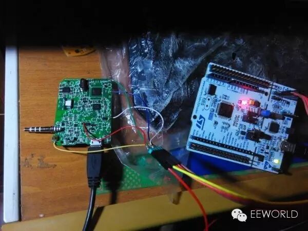
A few days ago, I posted an article titled “Disassembling the AiShua”, where I discovered that it uses the STM32F401CC microcontroller. This led me to wonder if I could modify it into a learning board for the STM32F401. After some exploration and experimentation, I successfully completed the modification, allowing for simulation downloads using STLink. I would like to share the process with everyone. First, let’s take a look at the connection diagram after the modification, which shows the STLink/v from the Nucleo64 development board connected to the STM32F401 board for simulation downloads.
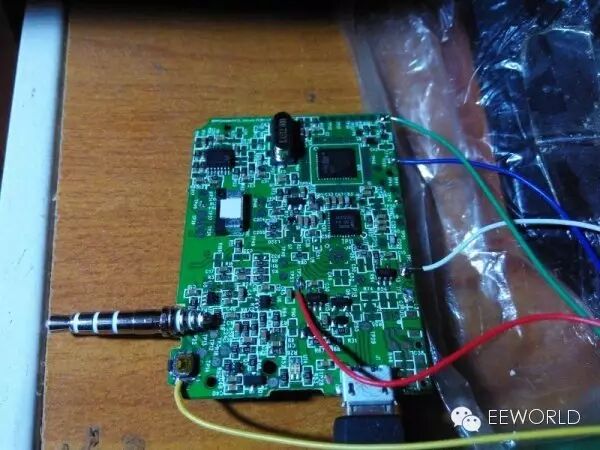
To achieve simulation downloads, the SWD interface needs to be brought out. This board does not have a dedicated download port, but there are some test points, including the SWCLK and SWDIO used by the SWD interface.
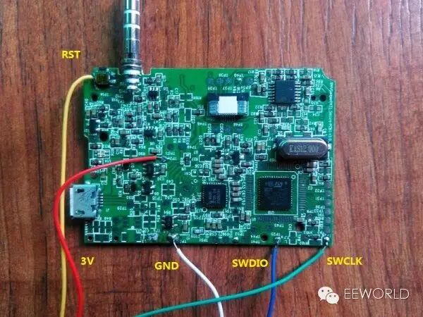
The position of the SWD interface has some pins that can connect in multiple locations, especially VCC and GND; the diagram shows just one of the possible ways. It is particularly important to note that although this small board supports both 48-pin and 64-pin packaged chips, some IOs do not correspond one-to-one, so one cannot simply use the more convenient 64-pin for measurement. For example, the LED pins are PA9 and PC7 on the 64-pin, but PB4 and PB7 on the 48-pin, which caused some confusion.
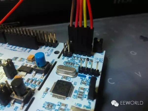
Remove the two short-circuit blocks on CN2 of the Nucleo64 development board, and then connect the Dupont wires to CN4, using only ports 1-5.
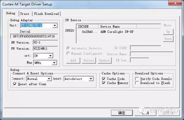
After connecting the SWD, connect the USB cables from the Nucleo and AiShua boards, then open any program in Keil, change the Debug to STLink, and if the chip can be recognized, it indicates that the connection is normal.
Once the SWD is connected, you can write a small program to test it. You can use any software for the test program, such as Keil, IAR, or CoIDE. Here, I used Keil and Mbed, also to introduce some modifications and porting in Mbed.
-
First, use a multimeter to find that the control IO for the LED is PB4 and PB7.
-
Then, create an STM32F401 example on the Mbed website (https://developer.mbed.org/compiler/), using the blink template, and change LED1 to PB_4.
-
Note that the program cannot be used directly at this point because Mbed’s program only provides the STM32F401RE program, which is not fully compatible with the STM32F401CC. Directly downloading the BIN file will not work; some modifications are necessary. One modification method is to change the source code, and another is to directly replace the obj and sct files. Below, I will introduce the method of modifying the source code, and the reference program provided later has replaced the files.
-
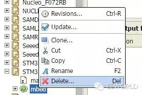
First, in the online editor on the Mbed website, delete the Mbed library from the project program, as the project defaults to include the compiled obj files, which cannot be modified directly.
-
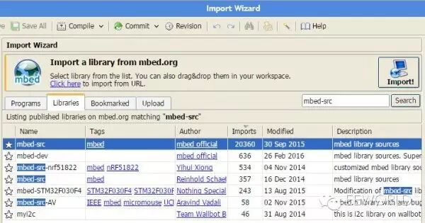
Then import the Mbed source code using the import function in the upper left menu, select to import libraries, search for mbed-src, and choose to import mbed-src. If you are feeling adventurous, importing the unstable development library (mbed-dev) is also an option.
-
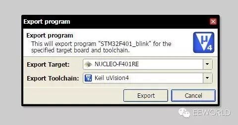
Once completed, you can export the entire project file in various formats; here, I chose the Keil4 format.
-
The exported file is a zip file, which can be opened with Keil, either Keil4 or Keil5. If using Keil5, ensure that the STM32F4 support package is installed. First, change the chip model to STM32F401CC, then modify the debugger to STLink, and add the programming algorithm for STM32F4xx 256kB Flash.
-
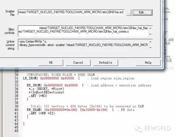
Edit the Scatter file under linker, changing the ROM and RAM addresses to 0x40000 and 0x10000, respectively.
-
Open the startup_stm32f401xe.s file and change line 54’s __initial_sp to 0x20010000.
-
Now you can compile the program and download it via STlink. If the LED starts blinking, it indicates success. Otherwise, carefully check the steps above.
-
The modified test program: To reduce file size, I directly replaced the corresponding obj and sct files. Those who need the complete source code can follow the steps above for modifications.
Additionally, I would like to introduce the method of downloading programs using DFU mode for those who prefer not to connect the SWD interface or want a simpler DIY approach.
-
First, download and install DfuSe_demo from the ST website at: http://www.st.com/web/en/catalog/tools/FM147/CL1794/SC961/SS1533/PF257916
-
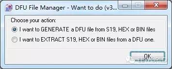
Run the Dfu file manager and select to generate a DFU file.
-
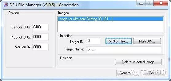
Then add the BIN or HEX file. It is recommended to choose the HEX file whenever possible, as this avoids the need to input addresses manually. After adding, you can generate the DFU file.
-
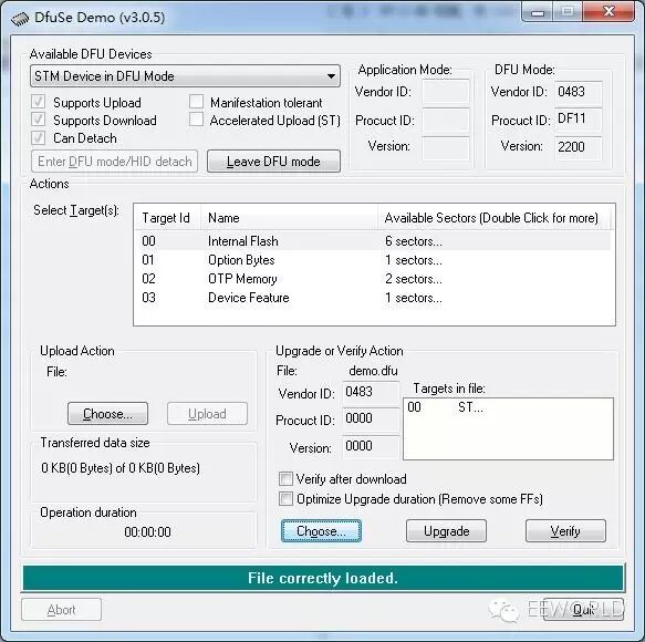
Use tweezers to short-circuit BOOT0 to VCC, then press the reset button. After releasing it, the board will enter DFU mode. If prompted to install drivers, they can be found in the directory where DfuSe_demo was installed. Open the generated DFU file to download (upgrade), and then run (Leave DFU mode).
Although there is not much information available about this small board, you can still try to explore it step by step. The next step could be to bring out the serial port and other GPIOs, which would allow for more functionalities. If you pair it with a small OLED, the effect would be even better. You could also experiment with audio port communication, which is another interesting application, although reference materials are scarce. For a board priced at just 1 yuan with free shipping, the AiShua is indeed a great value, and I encourage everyone to get one for research and experimentation.
The attachments mentioned in the article can be downloaded by clicking Read the original text.