Recommended in the past
Machine Vision Positioning and Component Size Detection Technology
Visual Positioning and Grabbing Methods for Parts
Three Minutes to Quickly Choose a Machine Vision Sensor
Sharing Useful PPT | Applications of 3D Machine Vision Technology in Intelligent Manufacturing!
A Summary of Common Algorithms and Development Libraries for Machine Vision
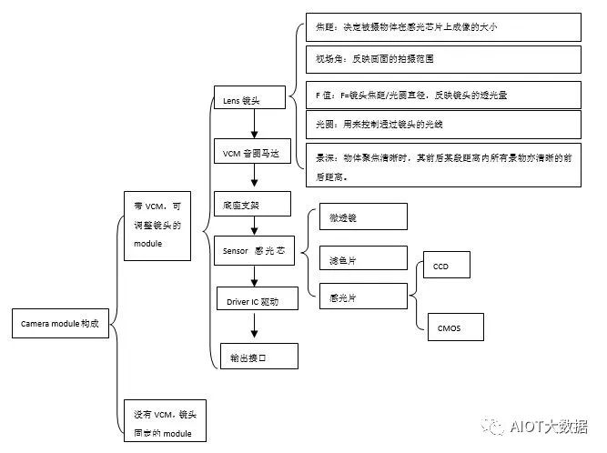
Camera Module Composition
Camera Lens Appearance and Distinction:

Lens Structure:
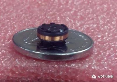
Structure Breakdown of the “Big Head”:
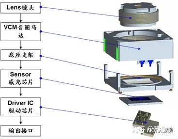
Structural Description:
-
Components:
Lens->VCM Voice Coil Motor->Base Bracket->Sensor->Driver IC->Output Interface
-
AF Module:
In the case of a constant focal length, the VCM changes the image distance to make the object clear on the sensor surface.
The AF module usually consists of a lens, VCM, sensor, base, driver IC, and power supply.
-
Lens: Composed of several lenses, usually glass and plastic lenses
-
VCM: The voice coil motor, which uses Faraday’s law to control the position of the spring piece by changing the current in the motor coil, thus driving the lens movement.
-
Sensor: Generally has CCD and CMOS types; compared to CCD, CMOS has advantages in manufacturing process, energy consumption, and cost, and is widely used in the industry. CCD performs better in image detail at low ISO, but only a few manufacturers produce it.
-
Base: Used to fix the module;
-
Driver IC: Used for control and communication;
-
Power Supply: Commonly 3.3V and 2.5V; when using the AF module, pay attention to provide power according to the instructions.
-
Main Parameters of the Lens
-
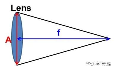
Focal length f. f=wL/W or f=hl/H. The typical effective focal lengths are f=3.5mm or 2.5mm
-
Field of View (FOV). Generally, larger FOV is preferred, but a larger FOV requires a smaller f and has more distortion.
-
F-value. Fno.=f/A. f is the focal length, A is the aperture diameter. The larger F is, the smaller A is, and the less light is admitted.
-
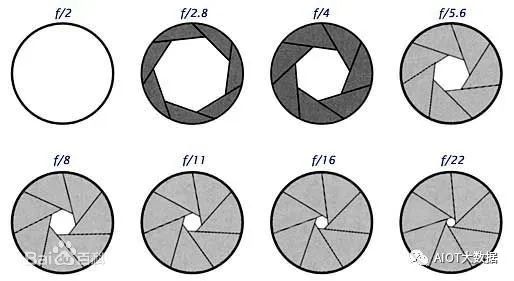
Aperture. A mechanical device inside the lens used to control the size of the aperture.
-
Depth of Field. The larger the aperture, the shallower the depth of field.
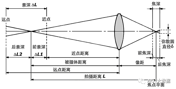
Depth of field = ΔL2 + ΔL1, the depth of focus corresponds to the depth of field.
Moreover, 1/f = 1/L + 1/(img_distance)
-
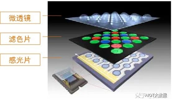
Sensor Structure
-
Microlens: Increases the aperture rate and significantly enhances sensitivity.
-
Color Filter: Helps the photosensitive chip to have color recognition capabilities. The photosensitive chip itself only senses light and electricity; through the color filter, it can separate different light components, thus affecting the processor’s restoration of the original color.
-
Photosensitive Chip: Converts light passing through the color filter into an electrical signal and transmits the signal to the image processing chip to restore the image.
Camera Imaging Principle:
Single-lens reflex camera (SLR): Unlike twin-lens reflex cameras (TLR), it has only one lens.
Single: The so-called “single lens” means that the photographic exposure light path and the viewfinder light path share one lens.
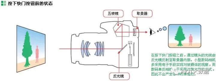
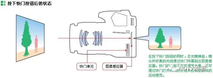
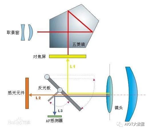
Reflex: “Reflex” means that a flat mirror in the camera separates the two light paths: during viewing, the mirror drops, reflecting the light from the lens to a pentaprism, and then to the viewfinder; during shooting, the mirror quickly lifts, allowing light to reach the photosensitive element CMOS.
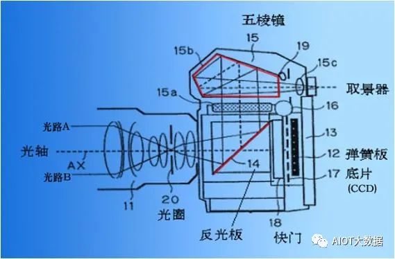
Through the unique design of the mirror, pentaprism, and shutter, one can control the image formation through the shutter, as shown below:
Lens
-
Position, Appearance, and Function of the Lens in the Camera:
The lens is a device that receives light signals and focuses them on the photosensitive device CMOS/CCD. The function of the lens: to focus light, forming an image of the scene on the CMOS/CCD, and to reduce aberration, the lens uses multiple lens combinations to achieve the required focal length for photography.

2. Composition and Parameters of the Lens:
The lens is a transparent optical component composed of one or more curved (usually spherical) optical glasses. The materials are usually plastic lenses or glass lenses.
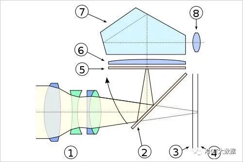
Light passes through the lens (1), is reflected by the mirror (2) to the ground glass screen (5). Through a convex lens (6) and reflected in the pentaprism (7), the final image appears in the viewfinder (8). When the shutter button is pressed, the mirror moves as indicated, the mirror (2) is lifted, and the image is captured on the CCD (4), consistent with what is seen on the ground glass screen.
The main parameters of the lens: A, eliminate as much flare as possible. B, clarity of image quality. C, CRA (Chief Ray Angle) should match to reduce shading. D, the aperture should be as large as possible. E, distortion should be as slight as possible, etc.
CRA: Chief Ray of Angle, Lens CRA < Sensor CRA, the difference should be within 2 degrees; otherwise, it is easy to cause shading or color deviation.
3. Main parameters of the lens:
(1). Focal length: The length of the lens focal length determines the size of the image, the size of the field of view, and the depth of field. Generally, for a single lens, it is the distance from the center of the lens to the focal point, while for a camera lens, it is much more complicated due to the combination of multiple lenses. Here, the focal length refers to the distance from the center of the lens to the clear image formed on the photosensitive element (CCD).
The focal length is equivalent to the scale ratio between the object and the image; when photographing the same target at the same distance, a longer focal length lens produces a larger image, while a shorter focal length lens produces a smaller image.
Object-Image Ratio:
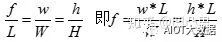
Explanation: f: lens focal length; w: image width (width of the object on the CCD target surface); W: width of the object; L: distance from the object to the lens; h: image height (height of the object on the CCD target surface); H: height of the object.
(2). Field of view: The horizontal field of view is commonly used to reflect the shooting range of the image. The larger the focal length f, the smaller the field of view, and the smaller the image range formed on the photosensitive element; conversely, the smaller the focal length f, the larger the field of view, and the larger the image range formed on the photosensitive element.
(3). F-value (aperture ratio): The F value refers to the brightness of the lens (i.e., the amount of light transmitted through the lens). F = lens focal length/aperture diameter. For the same F value, the aperture of a long focal length lens is larger than that of a short focal length lens.
(4). Aperture: The aperture is a mechanical device inside the lens that can adjust the size of the aperture to control the amount of light passing through the lens. Variable aperture (Iris diaphragm). The mechanical device used to control the size of the aperture inside the lens. Or it refers to the device used to open or close the lens aperture, thus adjusting the lens’s f-stop.
(5). Depth of Field: When an object is in sharp focus, all objects within a certain distance in front of and behind the object are also considered sharp. This distance from the front to the back where the focus is relatively clear is called the depth of field.
4. Optical Principles of the Lens:
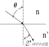
(1) Reflection and Refraction of Light. When light from medium 1 (air) enters another medium at an angle, part of the light is reflected, while another part enters medium 2 and undergoes refraction. For the lens, it is necessary to increase the refracted light as much as possible and reduce the reflected light. Official account “Mechanical Engineering Collection”, a gas station for engineers!
-
Snell’s law: n sin = n’ sin
-
Optical System
-
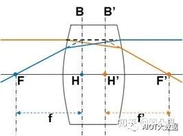
Principal Plane: A pair of conjugate surfaces where the imaging magnification equals 1, as shown in B, B’ in the figure.
-
Principal Point: The intersection of the principal plane and the optical axis, as shown in H, H’ in the figure.
-
Focal Point: The intersection of the parallel light rays entering the optical axis, as shown in F, F’ in the figure.
-
Focal Plane: The plane perpendicular to the optical axis where the focal point is located.
-
Focal Length: The distance between the focal point and the principal point, as shown in f, f’ in the figure.
-
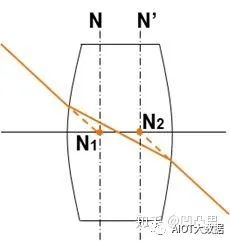
Node: When the incident light rays are parallel, the intersection of the extended lines of the two light rays with the optical axis. N1 and N2 are the object-side and image-side nodes respectively. When the object space medium and the image space medium are the same, the node coincides with the principal point.
-
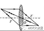
Characteristics of Ideal Optical Systems:
-
Light rays parallel to the optical axis must pass through the focal point on the image side after passing through the ideal optical system;
-
Light rays passing through the object-side focal point must be parallel to the optical axis after passing through the ideal optical system;
-
The direction of light rays passing through the node remains unchanged;
-
Any bundle of parallel light rays must converge at a point on the image-side focal plane after passing through the ideal optical system;
-
Light rays passing through a point on the object-side focal plane must be a bundle of parallel light after passing through the ideal optical system.
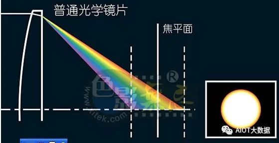
(2) Dispersion of Light: When white light passes through a prism, dispersion occurs, producing red, orange, yellow, green, blue, indigo, and violet light beams sequentially. This is because the refractive index of the aforementioned light increases in the same medium, causing an increase in the degree of deflection. Thus, different frequencies of light in the compound color light are separated.
(3) Pinhole Imaging: When a small hole is left in the middle of an opaque plate, light passing through the hole will form an inverted real image on the image plane. The clarity of the image is affected by the size of the hole; a small hole cannot sense chemical substances, while a large hole is blurry.
(4) Lens Imaging: Utilizing the specific refractive index and dispersion produced by different types of glass, the light rays are bent and concentrated in intensity and size, which is the most basic theory in lens design.
(5) Aberration: In optics, it refers to the deviation of the actual image from the ideal image determined by the theory of a single lens. These deviations are caused by refraction. They can be minimized through the combination of lenses.
Divided into two main categories:
A. Monochromatic aberration occurs even in highly monochromatic light, and is further divided into two categories based on the effects produced: one causes the image to be blurred and the other causes distortion. The former includes spherical aberration, comatic aberration, and astigmatism. The latter includes field curvature and distortion.
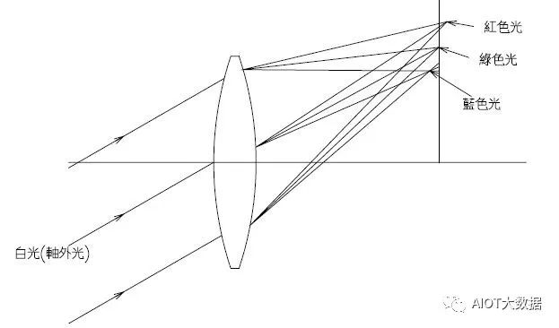
B. Chromatic aberration is abbreviated as color distortion: it is caused by the fact that the refractive index of lens materials is a function of wavelength, leading to different focal points for different colors. It can be divided into axial chromatic aberration and magnification chromatic aberration.
① Monochromatic aberration includes the famous Seidel’s five aberrations:
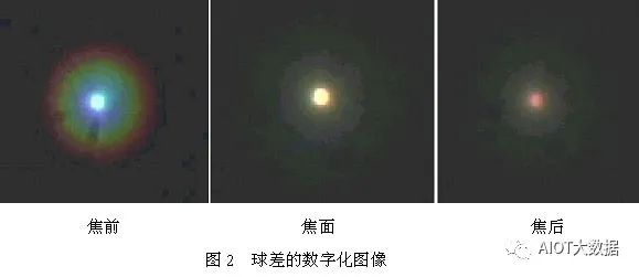
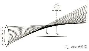
a. Spherical aberration: An ideal mirror (top) can converge all incident light rays to a point on the optical axis, but a real mirror (bottom) will have spherical aberration: light rays near the optical axis converge more tightly than those farther away, thus failing to converge at an ideal focal point. (Divided into negative and positive spherical aberrations).
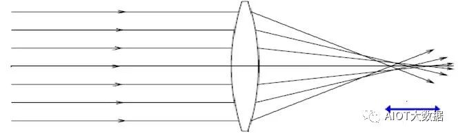
The phenomenon: The spherical aberration of the entire aperture beam forms a circular diffuse spot on the image plane symmetrical to the optical axis, which makes the image of the axial point blurry when serious.
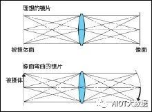
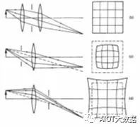
b. Petzval field curvature (Resolution): Field curvature occurs due to lens defects, causing the best real image plane to not be flat but curved for light emitted from a plane perpendicular to the principal optical axis.
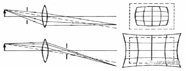
c. Distortion: Different positions on the image plane have different magnifications. Wide-angle lenses easily produce barrel distortion. Telephoto lenses easily produce pincushion distortion. Distortion is proportional to the cube of the vertical height of the object-image point from the optical axis, thus the distortion degree of the corners of the object-image is greater than that of the edges.
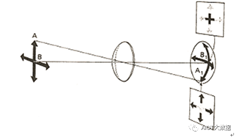
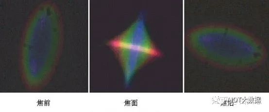
d. Astigmatism: A beam of light can be divided into horizontal and vertical vibrations. When light enters at an oblique angle away from the optical axis, there is a chance that horizontal and vertical light rays focus at different positions along the main axis. The image produced between the two focal points will become blurry, and the edges of the image will appear to spread.
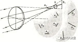
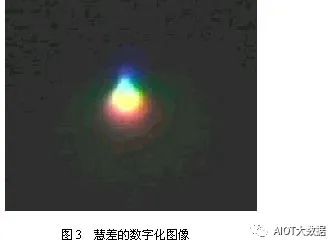
e. Comatic aberration: A point in the plane outside the optical axis emits a beam of parallel light, and after passing through the optical system, forms an asymmetric diffuse spot on the image plane. This diffuse spot is comet-shaped, with a bright, clear head and a wide, dim tail. The aberration caused by this off-axis beam is called coma aberration.
The phenomenon: The incident beam is symmetric with respect to the main ray, and the system has coma aberration, so the emitted light rays are also asymmetric, causing the image to not be a point but a comet-shaped diffuse spot.
② Chromatic aberration is divided into two categories:
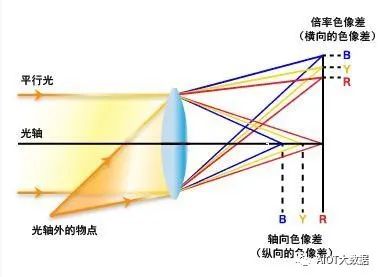
a. Axial chromatic aberration: Refers to the location on the optical axis where different colors have different focal points due to different wavelengths. For example, the focal point of red light is farther from the lens than that of blue light. This is an aberration unrelated to the object height. Axial chromatic aberration involves the focal distance of the image, causing color to appear diffuse or flared.
In general, large aperture lenses are prone to this aberration; reducing the aperture can minimize axial chromatic aberration and improve image quality.
b. Magnification chromatic aberration: An aberration proportional to the object height. It causes different wavelengths of light to have different image heights, forming a small spectrum in the ideal image plane. The color fringing phenomenon appears at the edges of the image due to the differences in light wavelengths, leading to color misalignment and forming a diffused color stripe.
(6) Lens Shading:
Causes: a. The angle of the incident light. When the angle of the incident light is small, the reflected light is less, and due to the coating on the lens surface, the light transmission is enhanced, reducing reflected light. This causes the brightness difference between the center and the periphery to increase. b. When the angle of the principal light entering is too large, the light cannot effectively enter the micro lens of the sensor, causing severe lens shading.
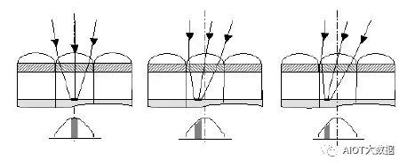
Compensation method: Compensate for the light of each channel R, G, B. Make the RGB channel all compensate to the same curve.
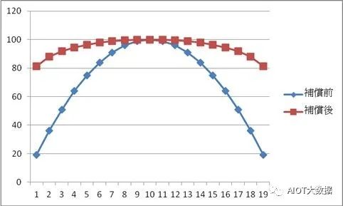
(7) Color Shading: Color shading is the issue of inconsistent colors between the periphery and center after compensating for lens shading (Y shading).
Causes:
A. The CRA (Chief Ray Angle) of the lens does not match the sensor. The lens CRA refers to the angle from the center of the lens to the imaging plane; the sensor CRA refers to the angle that the micro lens can receive.

B. Unreasonable sensor design. The sensor itself cannot effectively absorb the photons entering; when photons produce diffraction and scatter to other pixels, it is related to sensor design. For example, photons that should be absorbed by the R pixel are reflected into the G pixel area. This will cause color distortion.
C. Due to the previous compensation for lens shading (Y shading), the colors at the periphery and center are inconsistent (the RGB channel curves differ in color temperature).
(8) Indicators for Judging Lens Quality:
A. Mirror reflection and some special scenes causing flare and ghosting are difficult to eliminate and can only be minimized through lens coating or anti-reflective treatment on the inner surface.
B. High pixels combined with clear image quality indicate a good lens; simply having high pixels is not very meaningful.
C. The lens image circle (sensitive area) must be large enough to cover the sensor’s sensitive area, avoiding assembly errors that cause the lens’s imaging area to not enter the sensitive area.
D. The CRA (Chief Ray Angle) must meet conditions to reduce shading phenomena.
E. The aperture should be as large as possible, and the lens’s distortion should be as slight as possible.
Micro Lens:
1. Microlens in the sensor: Small lenses are installed above the photosensitive area of the pixel, so the photosensitive area is no longer determined by the opening area of the photosensitive chip, but by the surface area of the microlens. This greatly increases the aperture rate while improving sensitivity.
The structure of the CMOS sensor: 1. Microlens 2. Color filter 3. Photosensitive chip (photodiode) 4. High-speed transmission circuit
2. Principles and Functions of Microlenses:
The red box indicates the actual size of each “pixel”.
The red square indicating the pixel in the figure is the actual light-sensitive area in the CMOS. The surrounding T1, including VSS, are positions for auxiliary transistors or interfaces. Comparing the blue and red boxes, it can be observed that a large portion of the area in which a pixel is located cannot be used for light sensing, which is a significant waste. Using microlenses allows light entering the area between the red and blue boxes to converge into the pixel’s deep well.
Microlenses under an Electron Microscope in CMOS
With the lens, the light-sensitive range of each pixel is enlarged, as follows:
3. Effects of Microlenses on Images:
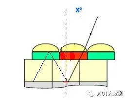
Microlenses serve to collect light, and this micro lens is not positioned directly above the pixel in each field of view. If the CRA (chief ray angle) of the lens does not match the CRA of the sensor’s micro lens, it will result in severe shading or significant color shading issues in the image.
Where:
Lens CRA: the angle from the center of the lens to the imaging plane.
Sensor CRA: the angle at which the micro lens can receive the maximum light.
If the lens CRA is less than the sensor CRA, the periphery will appear dark, as the light cannot reach the edges of the pixel;
If the lens CRA is greater than the sensor CRA, the light rays refract to adjacent pixels, causing crosstalk and color distortion between pixels, which is more pronounced at the edges of the image because the CRA increases from the center to the periphery.
4. Design Recommendations for CRA of Microlenses:
A. Lens CRA < Sensor CRA, otherwise light is easily reflected away;
B. CRA should match, with differences between Lens and Sensor within 2 degrees.
Note: CRA (Chief Ray Angle)
The chief ray is the light ray emitted from the edge of the object, passing through the center of the aperture and reaching the edge of the image. The chief ray angle is the angle between the chief ray and the parallel light ray.
1) Lens CRA: the angle from the center of the lens to the imaging plane.
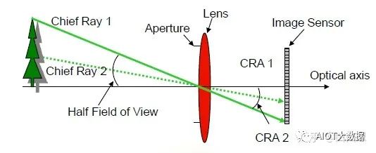
2) Sensor CRA is the angle at which the micro lens of the sensor and the photodiode are not in a straight line, which has a specific purpose. Normally, because there is a certain distance between the microlens and the photodiode, this design is also aimed at better matching the lens.
The maximum angle at which light can focus on each pixel from the lens’s side is defined as a parameter called the chief ray angle (CRA). The general definition of this angle is: the pixel response at this angle drops to 80% of the pixel response at zero degrees (when the pixel is perpendicular to the light).
The angle at which light enters each pixel depends on the position of that pixel. Light near the lens axis will enter the pixel at an angle close to zero degrees. As the distance from the axis increases, the angle will also increase. The CRA is related to the position of the pixel in the sensor, and their relationship depends on the lens design. Very compact lenses have very complex CRA patterns. If the lens’s CRA does not match the sensor’s microlens design, it will lead to undesirable light intensity passing through the sensor (also known as