
The RS-485 bus is widely used in industrial environments, which may experience high levels of electrostatic or surge interference. Engineers typically use gas discharge tubes and TVS diodes to build protection circuits. However, the capacitance of these circuits can be high, and improper application may affect communication. This article will introduce a low-capacitance peripheral circuit.
 Common RS-485 Protection Circuits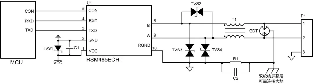
Figure 1 Protection Circuit 1
As shown in Figure 1, the protection circuit uses a gas discharge tube to dissipate most of the surge current at the interface, while a common-mode inductor filters out common-mode signal interference. The TVS further reduces the residual voltage after the gas discharge tube, thus protecting the subsequent circuit. The RSM485ECHT module, when using the protection circuit shown in Figure 1, can withstand contact electrostatic discharges of ±8kV, common-mode surges of ±4kV, and differential-mode surges of ±2kV, meeting the requirements for RS-485 node electrostatic and surge levels in most industrial sites.
Although the protection circuit shown in Figure 1 has strong protective capabilities, its capacitance is relatively high, with the junction capacitance of A-RGND or B-RGND being around 2.5nF. When there are many nodes on the bus using the protection circuit shown in Figure 1, the total bus capacitance becomes large, leading to signal reflections and a smoothing of signal edges, which degrades signal quality and may even cause communication anomalies.
 Signal Reflection Issues Caused by Bus CapacitanceWhen a signal is transmitted along the communication line and reaches the protection circuit at the RS-485 node, the junction capacitance of the protection circuit causes a change in the instantaneous impedance of the signal. A portion of the signal will be reflected, while another portion will become distorted and continue to propagate.
Figure 2 shows the differential waveform of a single RSM485ECHT node, while Figure 3 illustrates the schematic of the RS-485 bus connected to six protection circuits, with each node approximately 30cm apart, connected using twisted pair cables. Figures 4 and 5 show the waveforms at test points 1 and 6 (marked positions in Figure 3) when six circuits as shown in Figure 1 are connected to the bus. The rise/fall times of the waveforms are extended, and the waveform at test point 1 has become step-shaped.
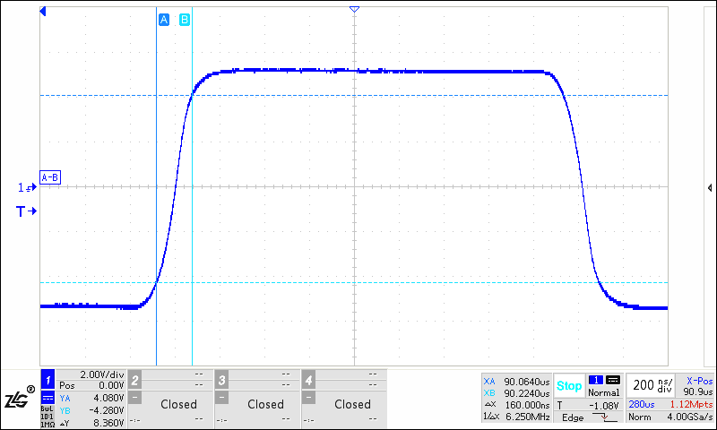
Figure 2 Differential Waveform of RSM485ECHT Single Node RS-485 Interface
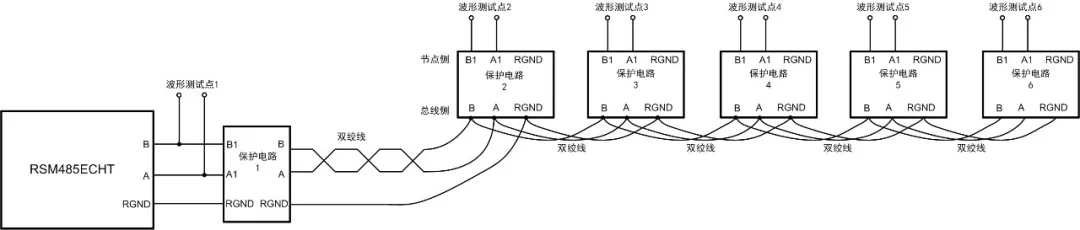 Figure 3 Schematic of Bus Connected to Six Protection Circuits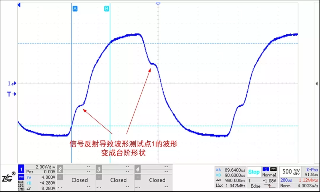
Figure 4 Waveform at Test Point 1 of RSM485ECHT Connected to Six Protection Circuits
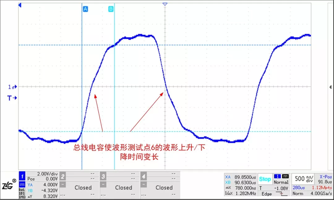 Figure 5 Waveform at Test Point 6 of RSM485ECHT Connected to Six Protection Circuits
The RS-485 interface of the RSM485ECHT has strong driving capabilities. Below are the test waveforms of commonly used RS-485 transceiver chips on the market under the same testing conditions. It can be seen that their waveforms have been severely interfered with, and the reflected waveforms have reached near the threshold level of the RS-485 chip, which may cause communication anomalies.Therefore, in practical applications, it is advisable to choose transceivers with strong driving capabilities.
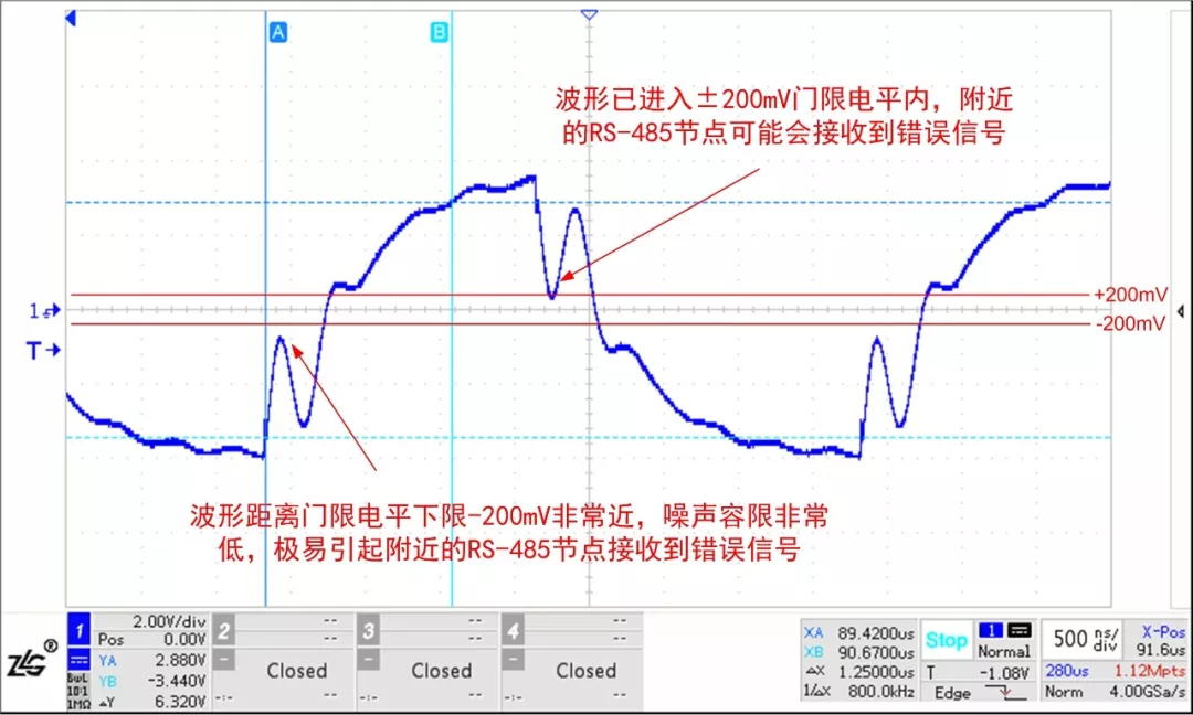
Figure 6 Waveform at Test Point 1 of an RS-485 Transceiver Connected to Six Protection Circuits
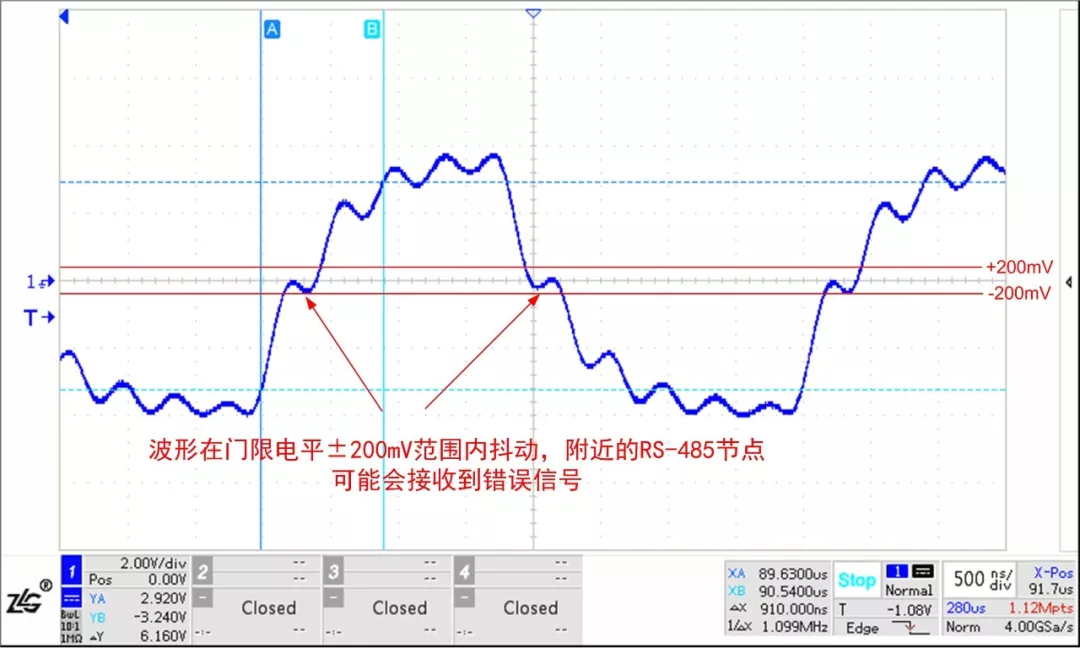
Figure 7 Waveform at Test Point 6 of an RS-485 Transceiver Connected to Six Protection Circuits
Low Capacitance Protection CircuitWhen there are many communication nodes, a protection circuit as shown in Figure 8 can be used, where the junction capacitance of A-RGND or B-RGND is only 20pF. Although the TVS junction capacitance is relatively large, the junction capacitance of ordinary diodes is very small. The junction capacitance of the TVS and ordinary diodes is in series, thus reducing the junction capacitance of the protection circuit.Using the circuit in Figure 8 for the networking shown in Figure 3, the waveform at test point 1 is shown in Figure 9, and the waveform at test point 6 is shown in Figure 10, where the waveforms have basically not changed.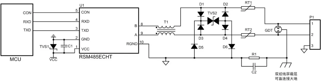
Figure 8 Protection Circuit 2 (Low Capacitance)
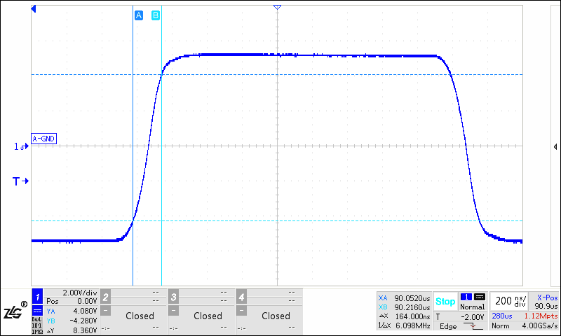
Figure 9 Waveform at Test Point 1 of RSM485ECHT Connected to Protection Circuit 2
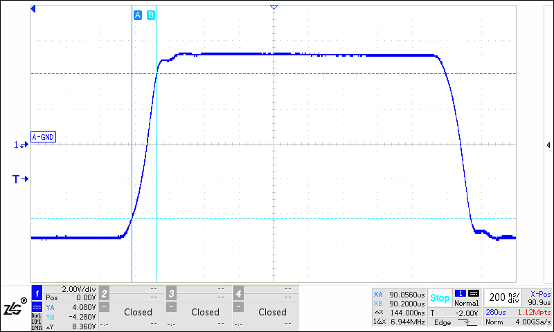
Figure 10 Waveform at Test Point 6 of RSM485ECHT Connected to Protection Circuit 2
ConclusionThe protection circuits mounted on the bus can cause changes in the instantaneous impedance of the signal, leading to signal reflections. When there are many nodes on the bus, the bus capacitance becomes large, which can interfere with the bus waveform and affect the quality of the communication signal. Therefore, to reduce the impact of the protection circuit on bus communication, it is advisable to choose transceivers with strong driving capabilities in practical applications. Additionally, if using the protection circuit shown in Figure 1, low-capacitance TVS should be selected, or a low-capacitance protection circuit as shown in Figure 8 can be used.