If the circuit is composed of three ideal components: R, L, and C in series, the equivalent complex impedance of the circuit is given by Z=R+j(ωL-1/ωC). When ωL=1/ωC, that is, ω0=1/√LC, the equivalent complex impedance Z=R becomes purely resistive, and the voltage and current at the port are in phase. This phenomenon is referred to as series resonance. Clearly, for series resonance, the required power supply frequency is f0=1/(2π√LC), also known as the natural frequency, which depends solely on the circuit parameters. The resonant impedance Z0 refers to the equivalent complex impedance of the circuit when resonance occurs, and it is evident that Z0=R; the characteristic impedance ρ refers to the reactance and capacitive reactance at resonance, ρ=ω0L=1/ω0C=√L/C, and the quality factor Q=ρ/R.
The first characteristic of resonance is that the impedance Z has the minimum magnitude and equals the pure resistance R; the second characteristic is that the loop current magnitude is maximized at resonance and is in phase with the power supply voltage; the third characteristic is that the effective voltage across L and C is the same and is Q times the effective voltage of the power supply. If Q is greater than 1, then UL0=UC0=QUs; far exceeding Us, this is known as the overvoltage phenomenon. The equivalent impedance of the series connection of L and C is 0, which is equivalent to a short circuit; the fourth characteristic is that the power supply voltage at resonance equals the voltage across the resistor, while the total voltage across the series connection of L and C is 0, meaning that at series resonance, the voltages across the inductor and capacitor are equal in magnitude but opposite in direction, thus canceling each other out. Therefore, series resonance is also referred to as voltage resonance; the fifth characteristic is that the active power at resonance is the power consumed by the resistor, and the maximum power is I0 squared multiplied by R, while the reactive power is 0, meaning that during series resonance, the power supply does not deliver reactive power to the circuit. The reactive power of the inductor and capacitor is equal in magnitude and compensates each other, exchanging energy periodically. The sixth characteristic is the relative frequency characteristic, which is commonly used to measure the degree of current attenuation when detuned. Let η=ω/ω0 be the horizontal variable, and I(ω)/I0 be the vertical variable. It can be derived that the relative current is related to the relative frequency η, which is the universal resonance curve. It can be seen that the relative frequency characteristic is related to the quality factor Q, the larger the Q, the sharper the curve, and the faster the current decays when deviating from the resonance point, indicating better frequency selection characteristics.
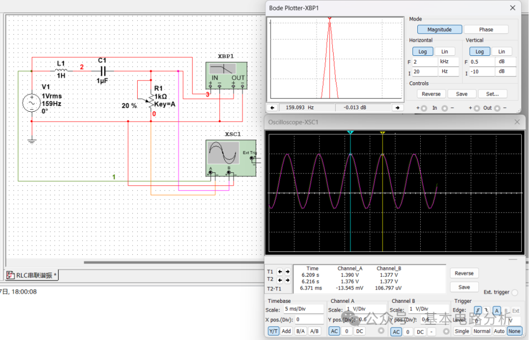
In the Multisim workspace, place an AC voltage source V1 with an effective value of 1V and a frequency of 159Hz, one 1H inductor L1, one 1uF capacitor C1, and one 1kΩ potentiometer R1, and then place one Bode plotter XBP1, one virtual oscilloscope XSC1, and one ground symbol, connecting them as shown. The theoretical analysis indicates that this circuit is in a resonant state. Start the simulation and observe the Bode plotter; you will see that when the frequency is 159.003Hz, the output signal (the voltage across R1) and the input signal (the voltage across V1) have the maximum ratio. Use the oscilloscope to simultaneously observe the voltage waveforms across V1 (channel A) and across R1 (channel B), which nearly overlap. The blue indicator line (T1) shows the difference between the two waveforms as -13.545mV, and the yellow indicator line (T2) shows the difference between the two waveforms as 106.797uV, indicating that during series resonance, the voltage across R1 is approximately equal to the voltage across V1. Readers can observe the voltage waveforms across the inductor and capacitor and compare them with the waveform of V1 to experience the characteristics of the circuit during series resonance.