On March 5, 2025, Labcenter Electronics Ltd. officially announced the release of Proteus 9 on its Facebook page. Proteus has a unique advantage that sets it apart from other EDA software. It is renowned for its integrated schematic capture, simulation (including microcontroller simulation), and PCB layout approach. While other EDA tools also offer PCB layout or SPICE simulation, what distinguishes Proteus is its deep integration of circuit simulation with embedded systems, allowing users to test and debug real firmware in a fully virtual environment. Today, I will share some thoughts on the new version of Proteus 9 and discuss its new features.
Proteus 9
For testing purposes, I installed the demo version of Proteus 9. This installation now includes a new feature: Portable Install. This allows installation in a user-defined single location, which is a useful option for users working on multiple PCs, such as installing to an external hard drive.
You can download Proteus 9 directly from the Labcenter Electronics official website. They offer a demo version for evaluation purposes.
Upon opening the program, I noticed that the startup screen is smaller compared to Proteus 8. In Proteus 9, the schematic graphics have been removed, and the new screen is brighter and more modern with a gradient background. In contrast, the older Proteus 8 screen was simpler, using a solid blue color. One seems to attempt to be flashy, while the other is straightforward.
Home Tab and Migration Tool
The Home tab is similar to Proteus 8, but the Start section now includes a new option: Migration Tool. This tool can also be accessed through the system menu: System -> Other Tools -> Migration Tool.
Design and New Framework
Proteus 9 has been completely redesigned. It is now a 64-bit program, enabling it to utilize more resources from your computer for faster performance and to handle larger, more complex projects. However, the most significant change is that Proteus is now built on a flexible framework that is not limited to Windows. This paves the way for future versions of Proteus to run on Linux and Mac computers, expanding its accessibility to a broader audience and making it a more versatile tool.
Icons
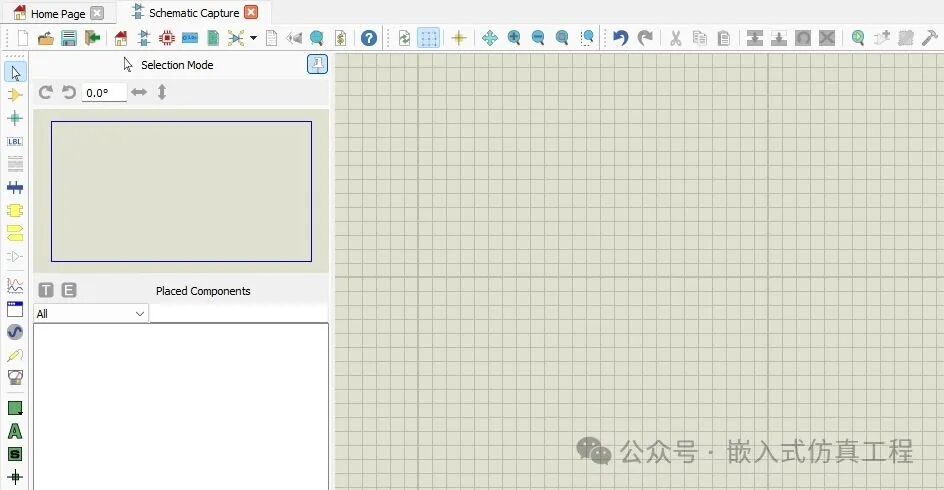
The older Proteus icons had a classic toolbar appearance typical of older Windows desktop applications, but with a simpler schematic-style look (thinner lines, more symbolic shapes). They appeared less 3D and used fewer bright colors. Now, changes have been made (though not to modern vector or flat design; the classic design remains), incorporating brighter colors and simple gradients. Some icons have a slight bevel effect, making them stand out on the toolbar, similar to the old design.
Themes
Proteus 9 introduces a theme feature. In the global system settings, you can switch between the standard mode theme and the dark mode theme. I believe this basic feature should have been implemented earlier.
Customizable Toolbars
Proteus 9 allows customization of toolbars in tabs or application modules. In the main screen of Proteus 9, the File I/O Toolbar and Application Module Toolbar are now located under the Home application module, which also applies to Schematic Capture and other modules. Related toolbars are grouped under their respective tabs/modules. You can drag and drop them into the current module. However, even if you close Proteus without saving the project, the toolbar positions will be retained. The downside of this feature is that there is no reset option; you must manually reposition the bars to their default locations.
The mode selection toolbar groups (e.g., simulation tools and 2D graphics) can be collapsed or expanded. You can switch between modes in the collapsed group by right-clicking the icon size option.
You can also unpin the object selector and overview window to maximize the editing window. In Proteus 8, this was achieved by right-clicking the auto-hide feature in the object selector. In Proteus 9, the pin icon at the top of the overview window is used for this purpose. However, I found that this feature is not as responsive as in Proteus 8. Unpinning the object selector and overview window and continuing to work in the editing window does not cause them to hide immediately unless you wait after clicking the pin icon. In Proteus 8, this action was instantaneous.
System Scope
Another new feature is the system scope in schematic capture. This option is located in the animation control toolbar. It is similar to the oscilloscope tool in the virtual tool mode selector but runs during simulation. This allows placing real-time probes on the circuit during simulation, a feature lacking in the default oscilloscope tool. This is, so far, the only significant improvement I believe Proteus 9 has made.
Schematic and PCB Module Responsiveness
In Proteus 9, the responsiveness of the schematic capture editor window is slower compared to Proteus 8. Placing, dragging, or using 2D shapes causes lag in the editor window. On the other hand, the editor in Proteus 8 provided smooth and quick responses for components and 2D graphics. This is a major flaw or disadvantage in Proteus 9. The PCB module has the same issue. Additionally, zooming is not as smooth as in Proteus 8.
In Proteus 8 Schematic Capture, if you run a simulation without any components, an error message is displayed, such as:
“Nothing to simulate! Simulation FAILED due to partition analysis error(s).”
However, in the new version of Proteus, running a simulation without any components does not display an error. Instead, the log indicates that netlisting and analysis were successful.
I’m not sure if this is a bug or intentional, but in my opinion, generating an error for an empty simulation would be a better approach.
Managed Libraries
When designing electronic circuits or PCBs, users rely on library components from various sources, including Labcenter, web vendors, or custom components. By default, Proteus treats all parts equally, allowing placement and dynamic editing.
The Managed Libraries feature introduces a controlled, approval-based workflow for component usage. It ensures design accuracy by only using approved parts. Library administrators select and lock key details to prevent user modifications. Version control tracks updates, and Proteus checks for consistency. This simplifies design and reduces errors. I find this feature more useful for PCB design than for schematics. I have not yet explored how it integrates with Git version control or online library sharing. I will share more information on effective usage after further investigation.
Proteus advises not to manually copy the Proteus 8 library into the Proteus 9 library folder. Although the Proteus 8 libraries can be read in Proteus 9, they are not writable in the new version.
MicroPython Integration
Proteus VSM (Virtual System Modeling) has enhanced support for MicroPython, a simplified version of Python designed for embedded systems. This update includes support for more development boards (such as Pyboard) and improved integration with actual communication protocols like SPI and I2C through the FT232 chip. Additionally, further improvements will be made to the Visual Designer and IoT tools.
Final Thoughts
Since I primarily use Proteus for simulation and schematic capture, I only tested the schematic capture module. Other modules (like PCB) have more updates.
An honest assessment of Proteus 9 is that Labcenter prioritized business expansion in this version. The main update is the transition to a 64-bit architecture, paving the way for future Linux and Mac versions. However, many of the new features in Proteus 9 could have been added to Proteus 8, rather than justifying a brand new version. Although Proteus 9 SP1 was released after beta testing, it still does not reach the stability of Proteus 8, especially considering the lag issues in the schematic and PCB editors.
Overall, while Proteus 9 introduces some useful features, it still requires significant optimization before it can be considered a truly stable and improved version over Proteus 8.
Welcome to follow (for operational reference articles: Send a message to the public account for operation), click the blue text at the top “Embedded Simulation Engineering” or long press to identify the QR code to follow