If you don’t want to miss my updates on Zhihu, remember to check the public account in the upper right corner and set it as a star, and take down the stars to send to me.

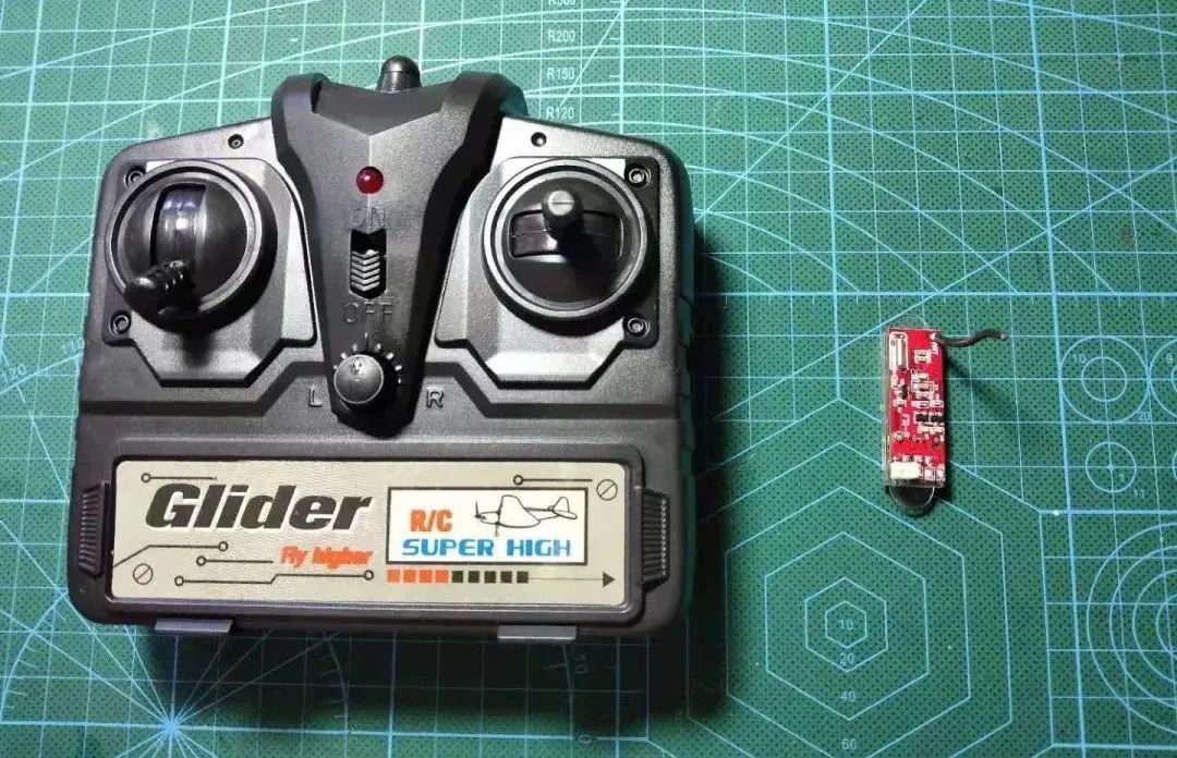
 As a DIY enthusiast, I can’t stop! Today’s project involves modification + DIY, tackling both aspects.A while ago, a friend contacted me, asking me to modify a Huakeer remote control to make it compatible with the Feixiong receiver board. He sent me a Feixiong transmitter-receiver board and a Huakeer remote control, and I would like to thank this friend for his sponsorship.Below is a remote control receiver set called Feixiong, which is likely used in some small 2-channel remote-controlled airplanes. To enhance the control experience, I will modify the Huakeer remote control to make it compatible with Feixiong.
01
General Idea of the Modification
To make the Huakeer compatible with the Feixiong receiver board, I first need to understand the communication protocol of this Feixiong remote control set, specifically how the remote control communicates with the receiver board. Once I understand how the communication works, I can mimic the remote control and send data to the receiver board, effectively creating a “fake remote control ” that sends data to the receiver board using the same communication protocol, making the receiver board believe it is receiving commands from the remote control.
However, there is a problem: I do not have the source code for the Feixiong remote control, so I have no way of knowing what protocol the remote control uses to communicate with the receiver board, which puts me in a deadlock.  But hardware is dead, and people are alive
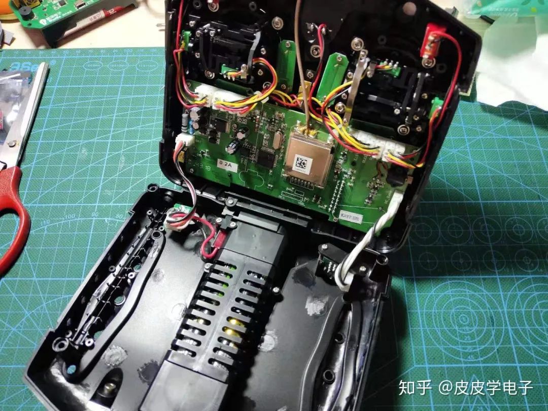
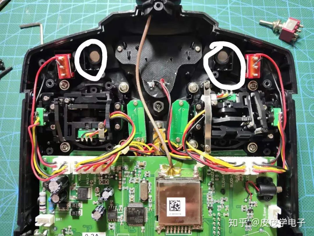
 . Without the source code, I can only interpret the communication protocol from the hardware circuit, so I first opened the remote control’s casing:
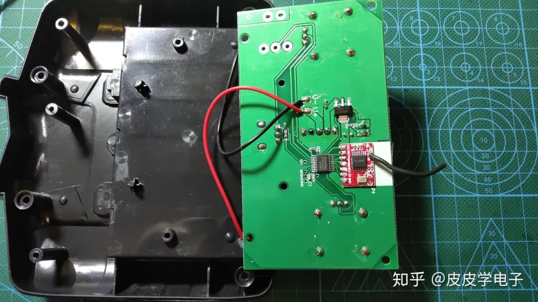
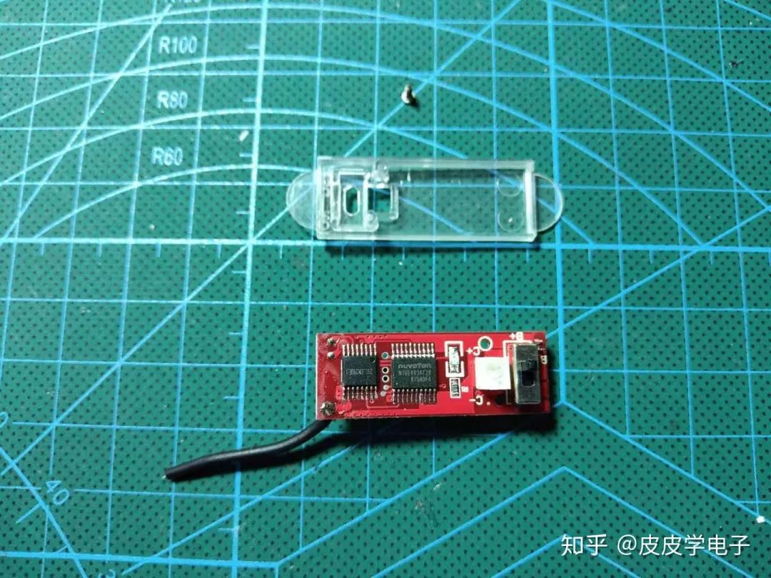
Upon examining the circuit, I found it relatively simple, which made it easy for me to interpret the functions of all components. Here is a close-up of a transmitter chip:
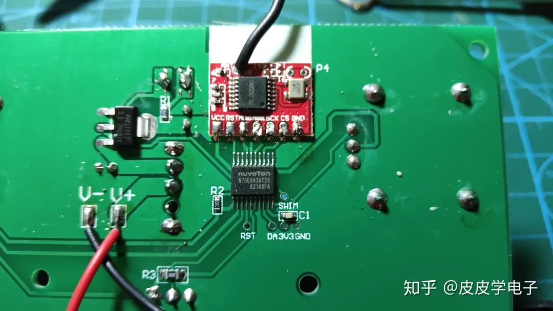
From this, it is easy to see the solution used by Feixiong: the microcontroller is the 76E003 from Xintang, and the wireless chip is the lt8920, with communication between the microcontroller and the wireless chip using the SPI bus.
Without the source code, I can only steal the communication content between the microcontroller and the wireless module from these pins, so the logic analyzer comes into play:
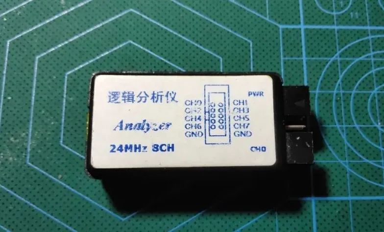
Some of you may not know what a logic analyzer is; its function is somewhat similar to that of an oscilloscope. An oscilloscope can interpret both analog and digital signals, while a logic analyzer is generally used to interpret digital signals. I bought this “beggar version” for 25 yuan, and after connecting it to a computer, I can view the data.
Since it uses a 4-wire SPI bus, plus one ground wire, there are a total of 5 wires connected to the logic analyzer.
After opening the logic analyzer software and clicking start, I powered on the remote control, and the following image appeared:
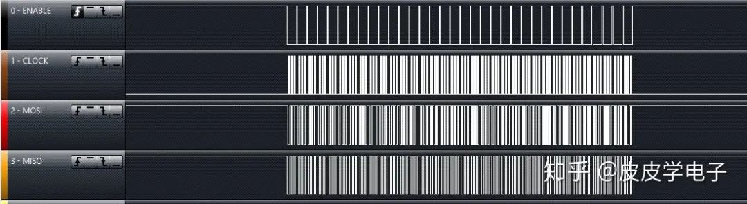
This captures a segment of communication data between the microcontroller and the wireless module 1 second after powering on. When zoomed in, the logic analyzer software displays the communication content:
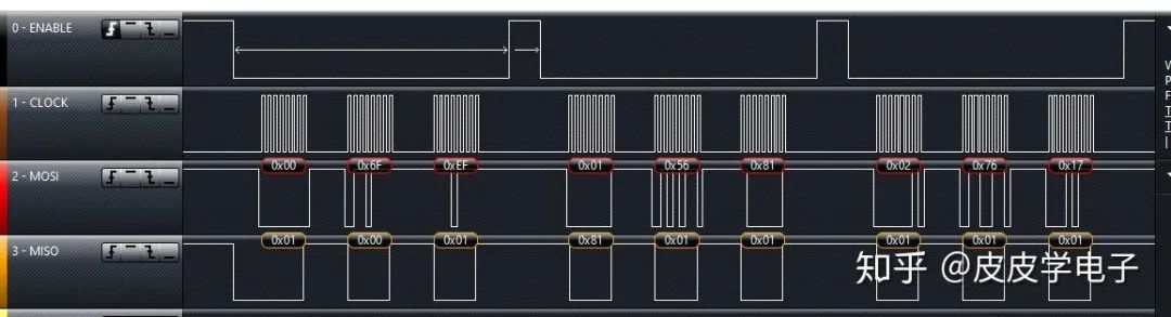
Based on this data, I interpreted what the microcontroller and the wireless chip were “saying”. Next, I will show how to replicate a “fake remote control”.
02
PPM Signal Forwarding
Model remote controls like Huakeer generally have a simulator function, allowing them to connect to a computer to play some flight simulation software. Therefore, the core of my modification is to capture the simulator signal output from the remote control, interpret its content, and then control the wireless chip to send data. Below is the simulation port of the Huakeer D7 controller:
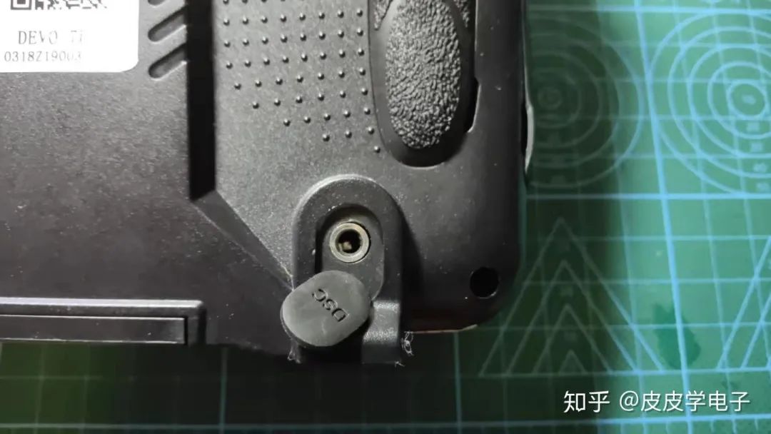
The signal output from this port is a type of signal called PPM, which is a square wave signal that can transmit up to 9 channels of data using a single data line, with a period of 20ms. I found a diagram to explain the principle of PPM:
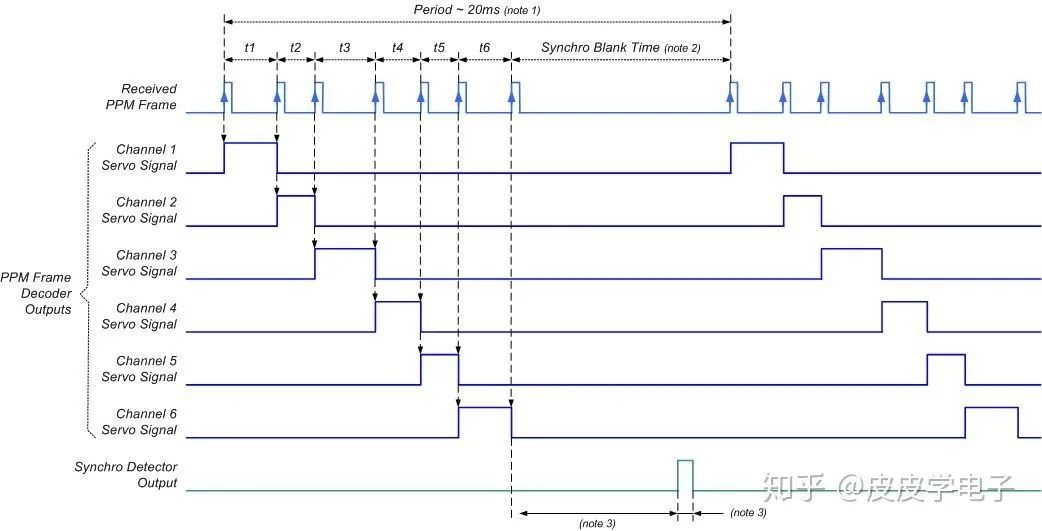
It can be seen that the distance between two rising edges corresponds to the PWM value of each channel, so I will also use a microcontroller to interpret the PPM signal sent by the remote control to obtain the value of each channel, ultimately controlling the wireless chip to transmit the corresponding data.
To clarify the PPM signal waveform of Huakeer, I also used the logic analyzer to obtain data:

It can be seen that the PPM waveform output by Huakeer is negative logic, meaning that the distance between two falling edges represents the data value of each channel.
At this point, I have analyzed the Feixiong remote control protocol and the Huakeer PPM signal, and now I will proceed to create the “fake remote control“. 
03
Creation of the Forwarding Board
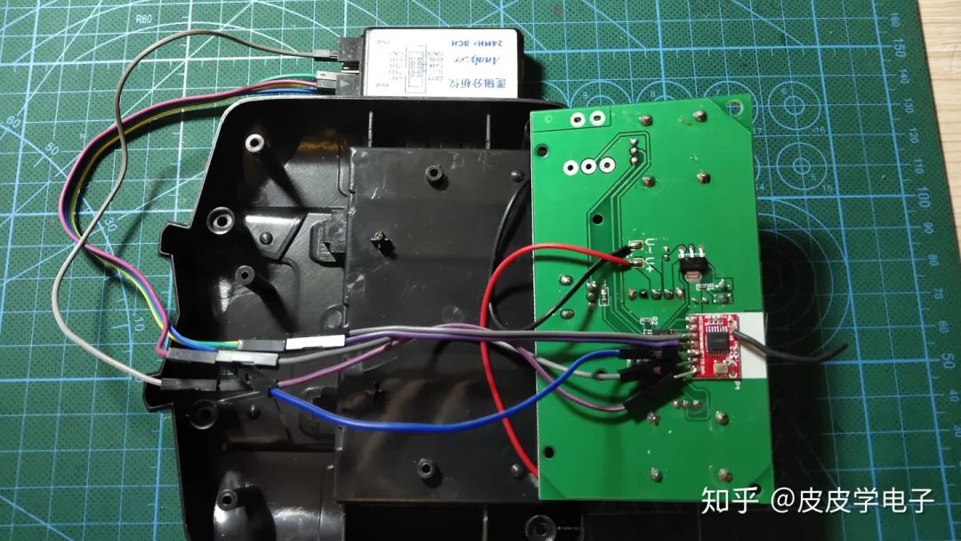
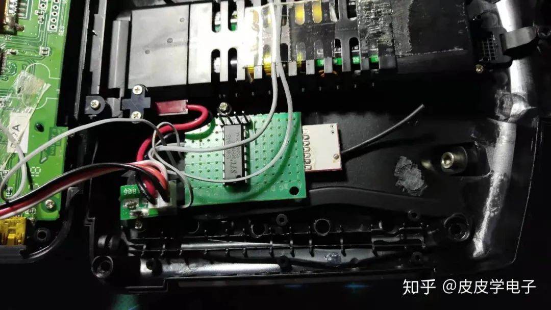
The “fake remote control” is essentially a forwarding board that captures data from Huakeer and transmits it to the Feixiong receiver board. So I prepared a wireless module and a microcontroller to solder a circuit, using the STC15W408AS microcontroller:
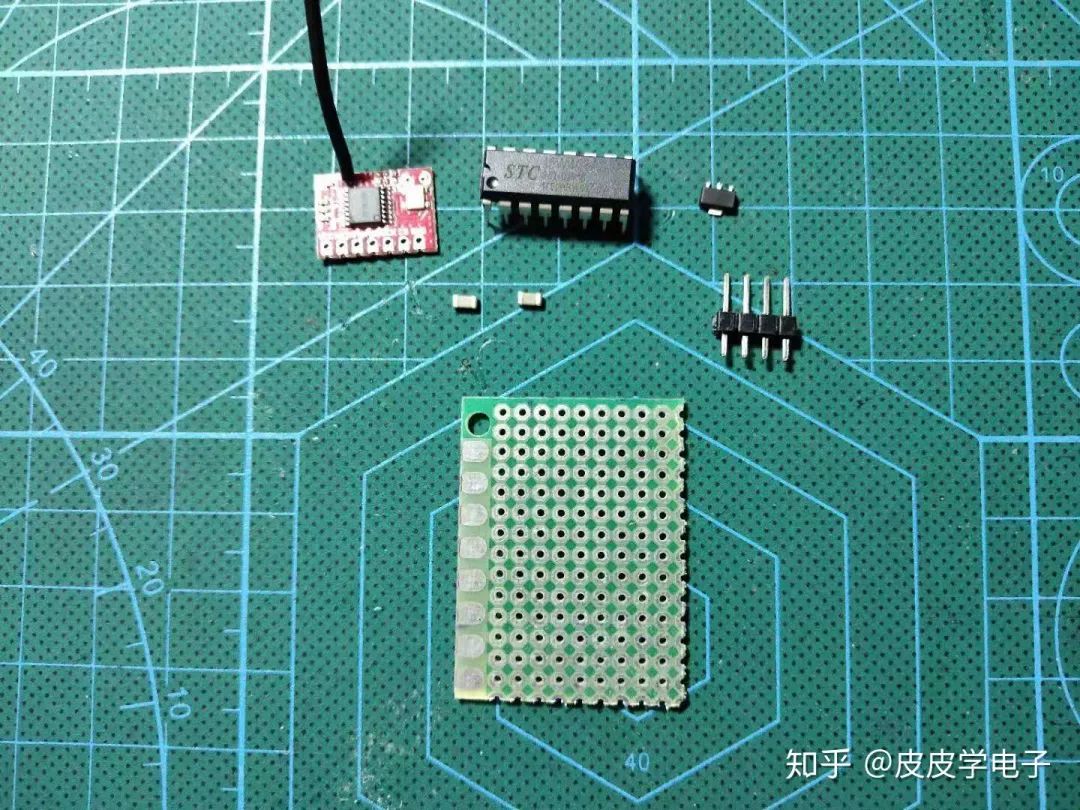
The principle of analyzing the PPM signal is to use an external interrupt to trigger a timer, which allows me to calculate the time between each falling edge to derive the corresponding PWM value data for each channel. Then I can send it out to control the receiver board!
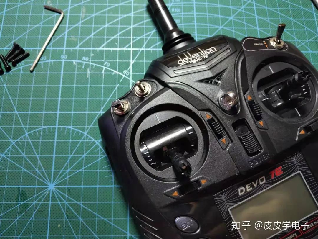
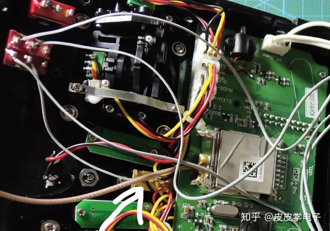
After burning the program, I disassembled the Huakeer D7e:
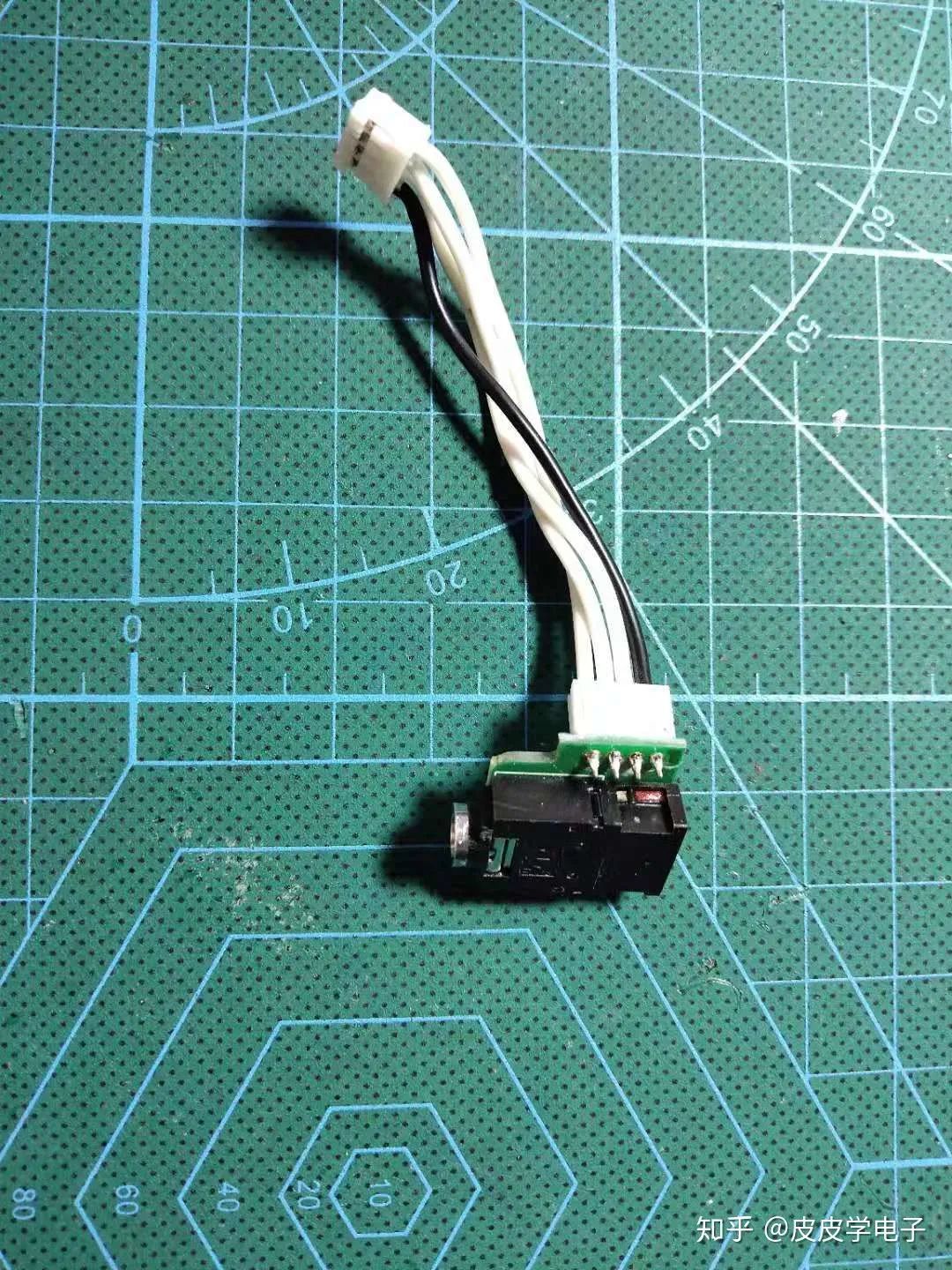
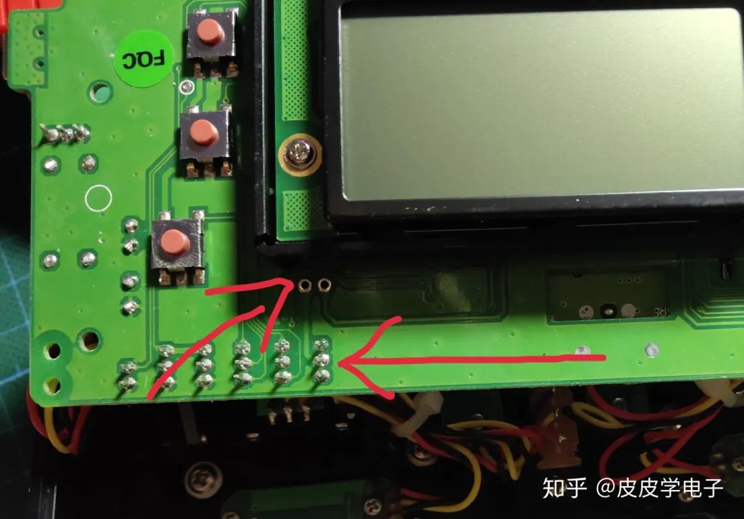
Finding the PPM port, I opened it:
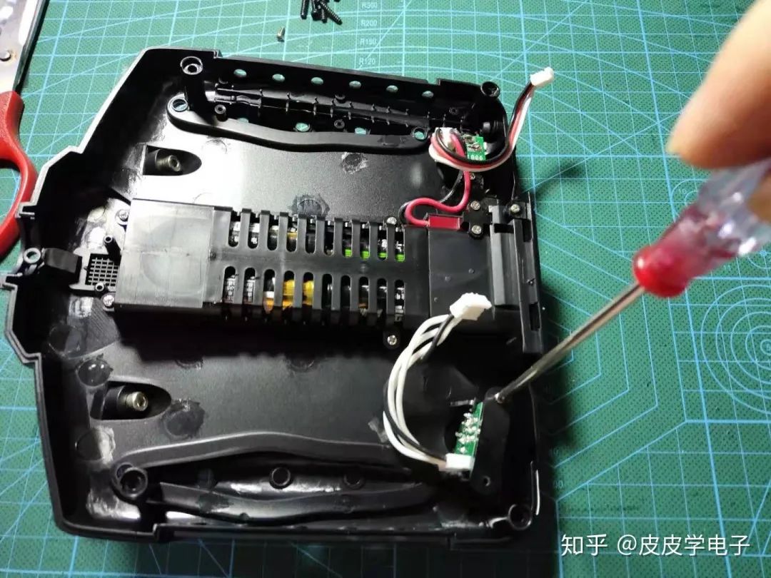
As shown in the figure, it is a 3.5mm headphone jack:
Thus, my forwarding board can read data from this port, so I prepared a switch to control the power of this module:
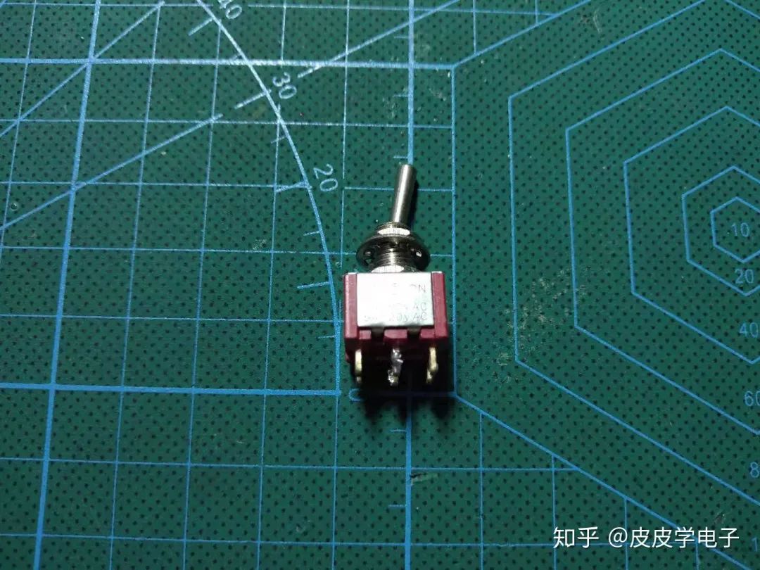
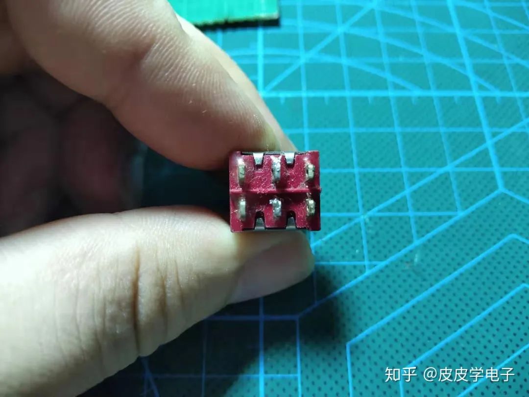
This switch is dual-channel, controlling both the power of the forwarding board and the input of the PPM signal:
In fact, the top of the remote control has several ports reserved for expansion, but they are covered with stickers on the front:
So I installed the switch:
04
Modification of the Circuit
I cannot directly connect the power of the forwarding board to the remote control’s battery, as this would keep it powered on continuously, draining the battery. Therefore, I need to connect the power of my forwarding board in series with the power switch of the remote control.
In the left terminal of the Huakeer D7e, the rightmost terminal is connected to the power switch:
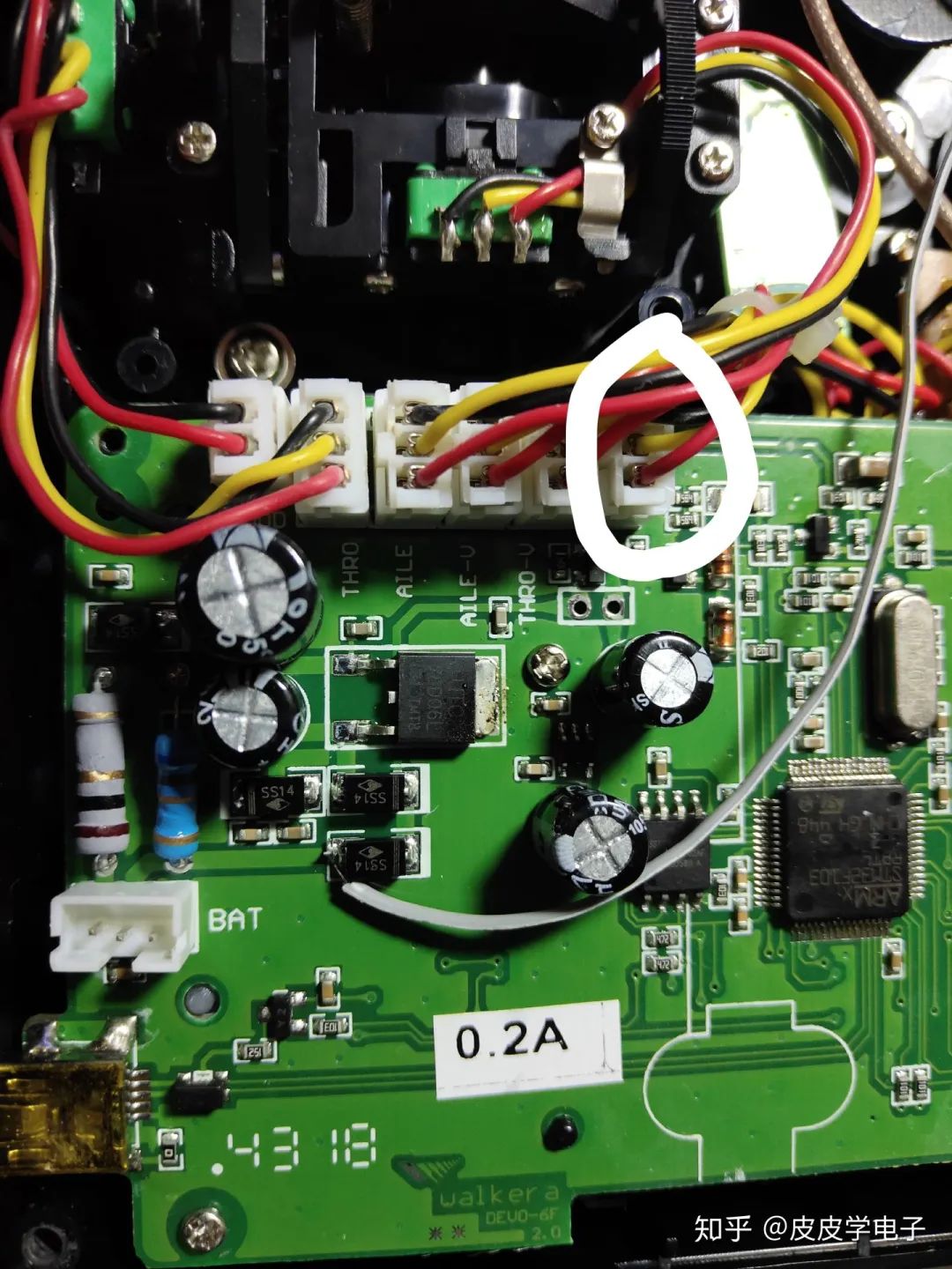
Based on the circuit structure, I found that the middle wire of the switch terminal is directly connected to the positive terminal of the battery through a diode, and the wire is relatively thick, making it suitable for me to draw power from here:
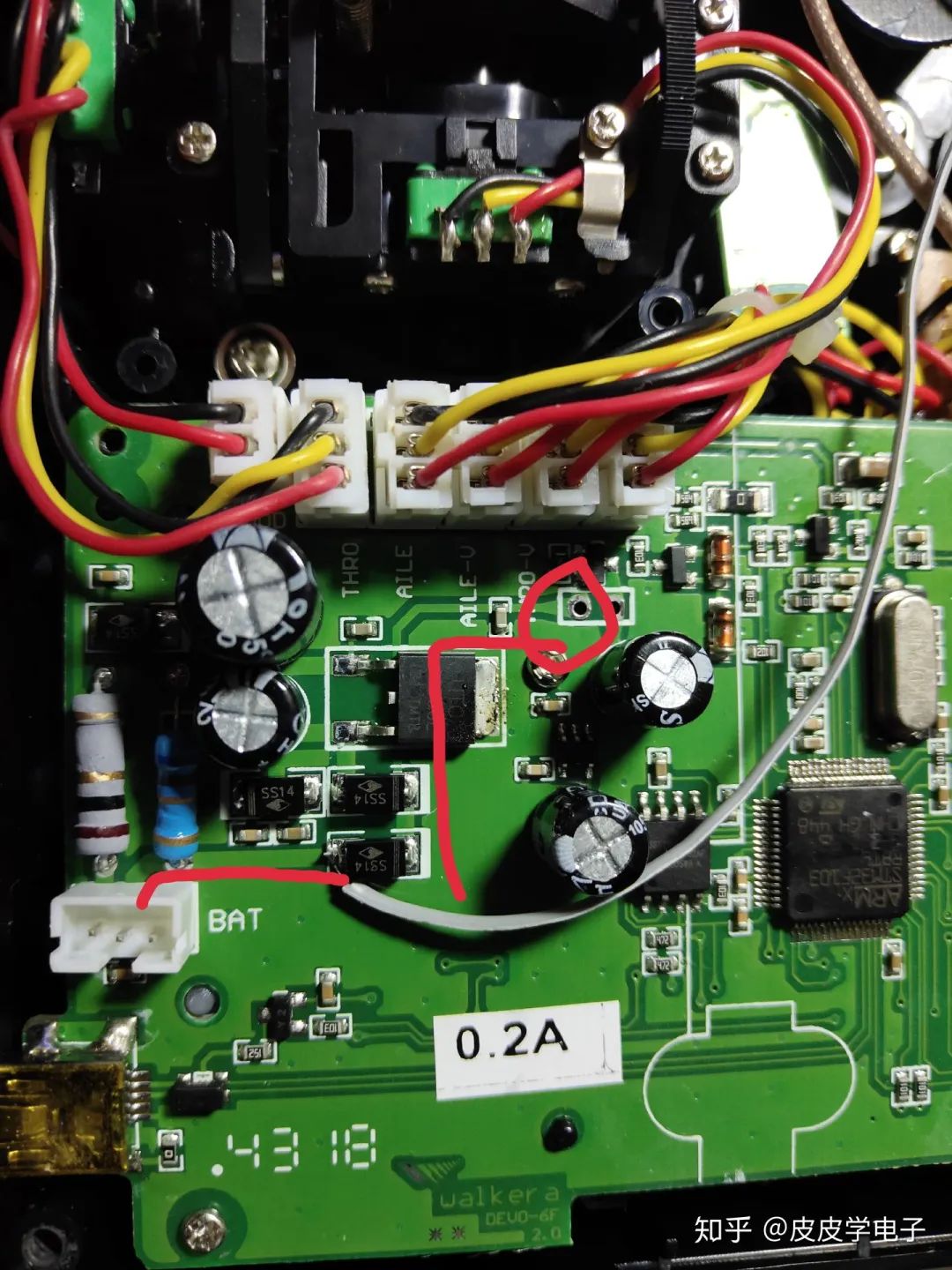
So I connected the power line to the switch, allowing the forwarding board to receive power when the switch is pushed:
After soldering the PPM signal line and power to the forwarding board, I completed the modification!
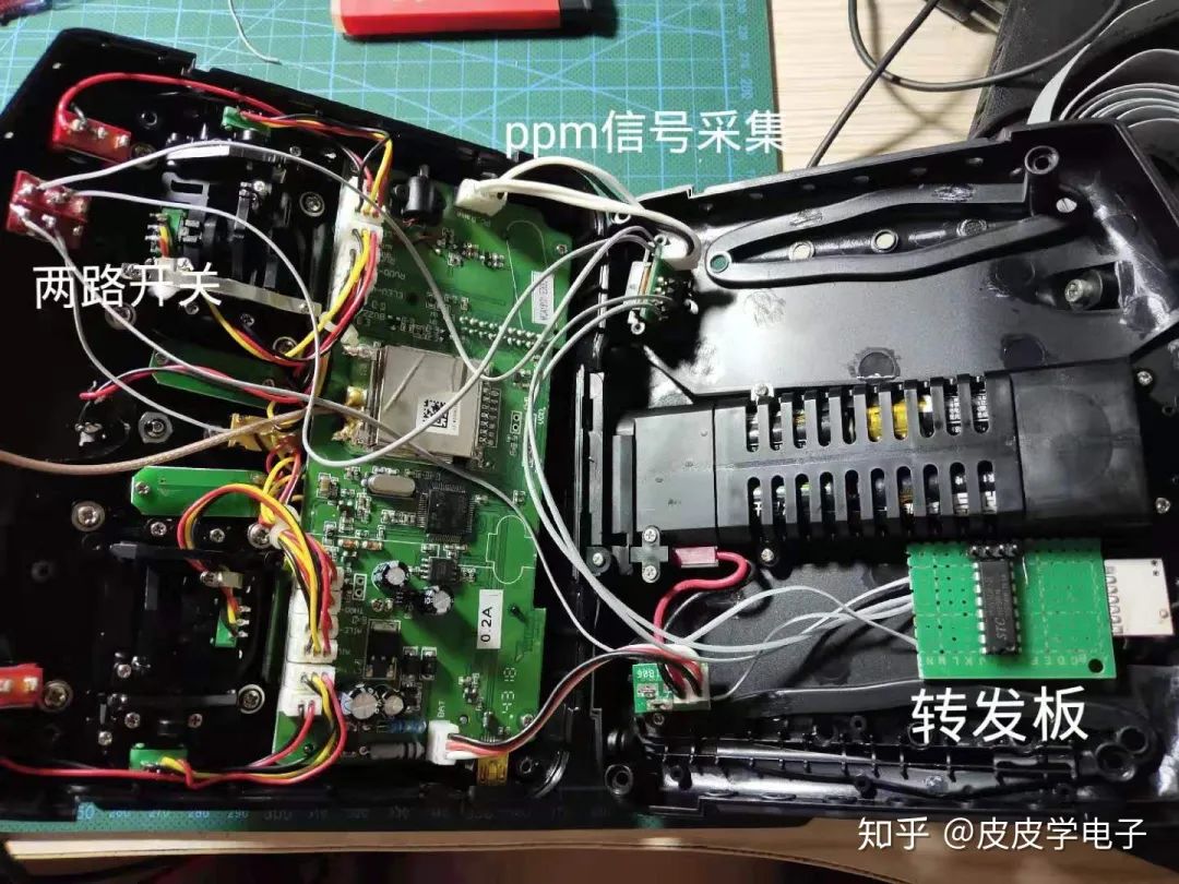
The module is attached to the base with double-sided tape, and it’s done.
At this point, the Feixiong receiver officially supports the Huakeer D7e remote control!
05
Aircraft Construction
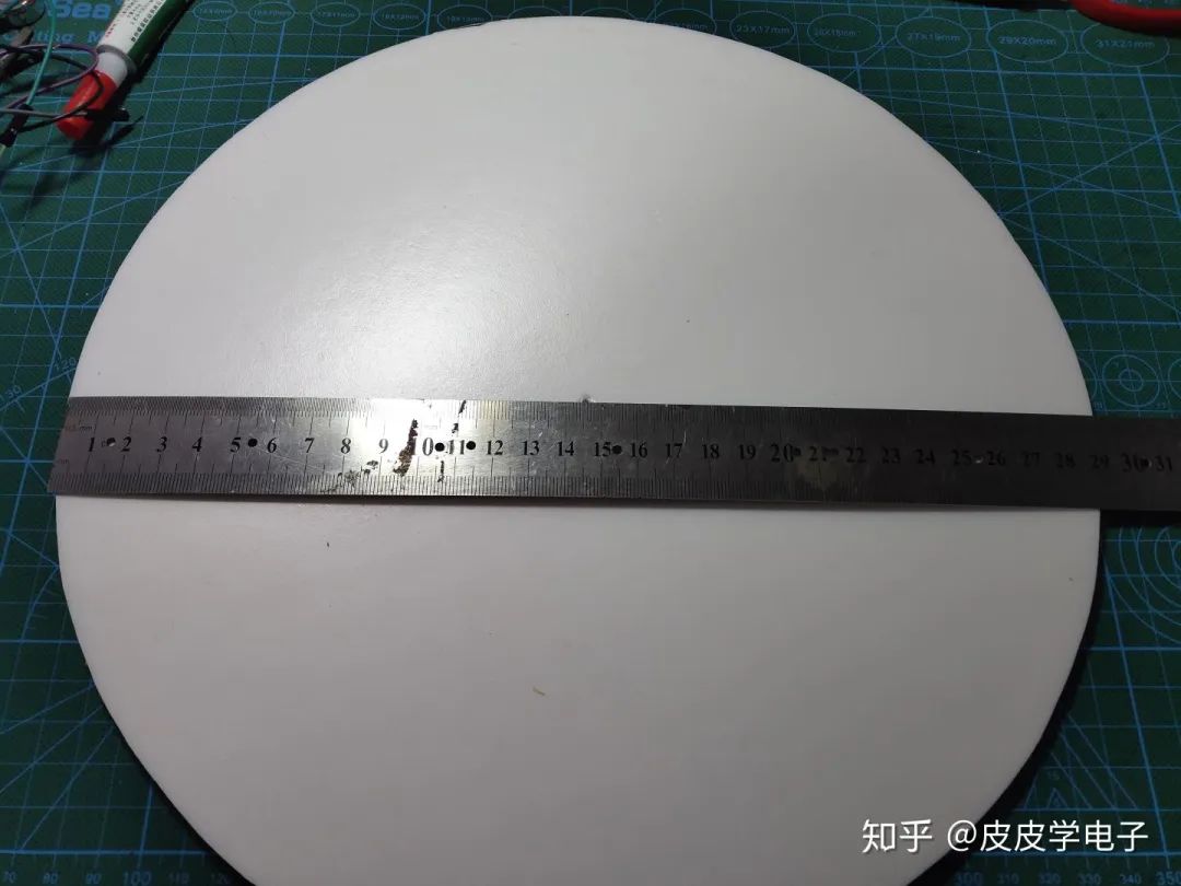
Without an aircraft to test the effect, I prepared to make a uniquely shaped flying saucer. First, I drew a circle with a radius of 14.5cm on a KT board.
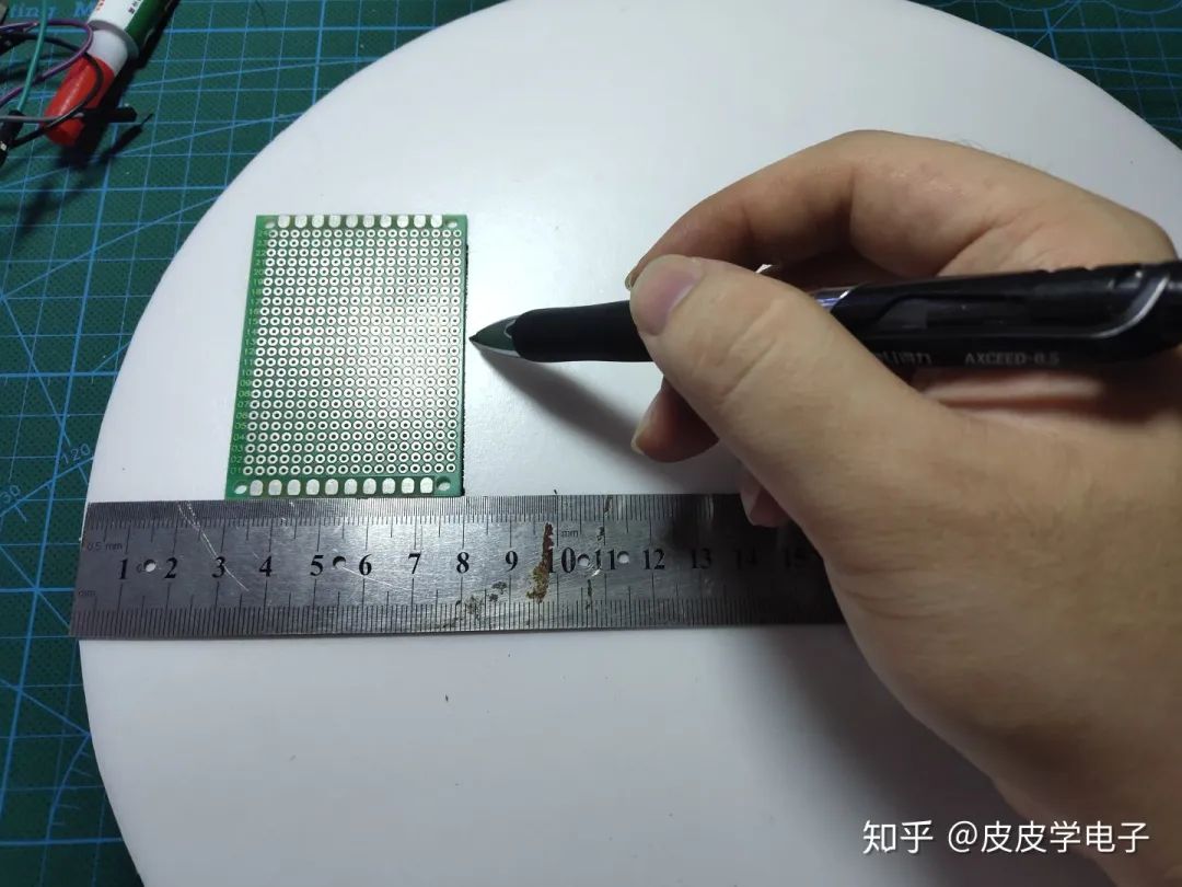
At about 8cm radius, I made a vertical line:
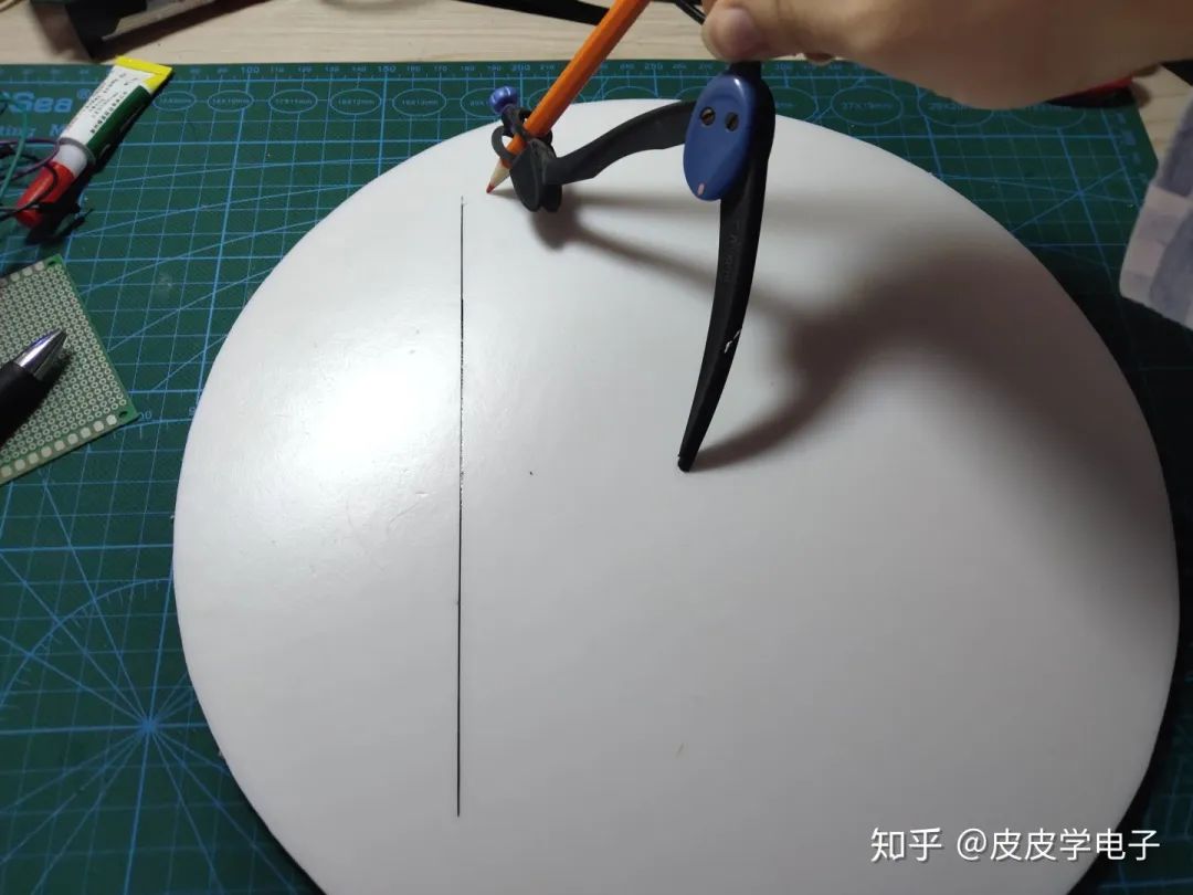
Then I drew a concentric circle with a radius of 12cm:
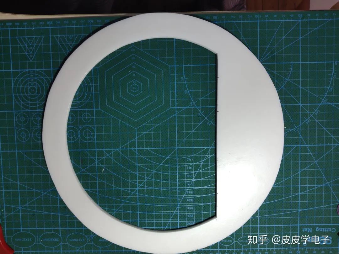
Then I cut it out:
In the cut-out part, I drew the shape of the vertical tail:
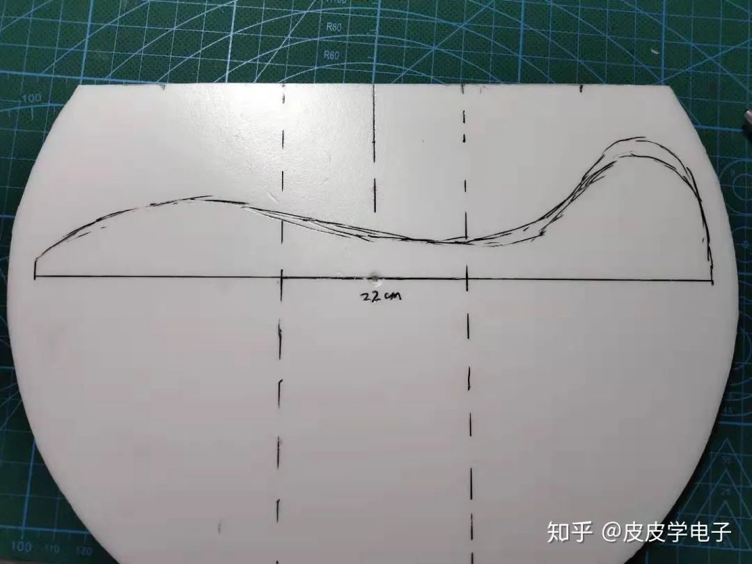
Then I cut it out:
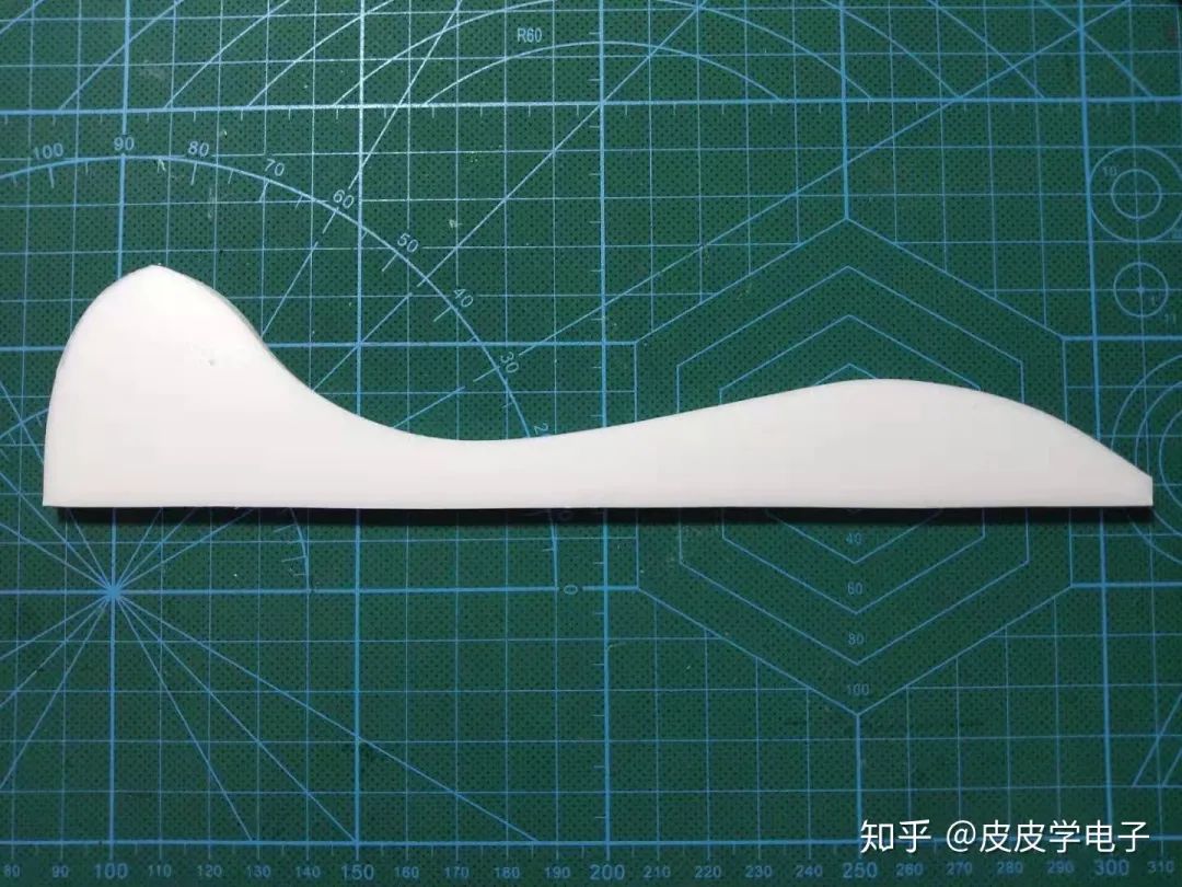
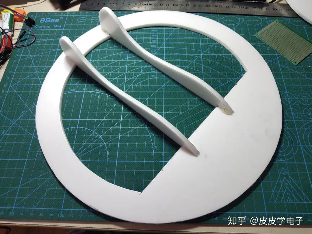
And made a copy. Using the ancestral hot melt glue, I installed it:
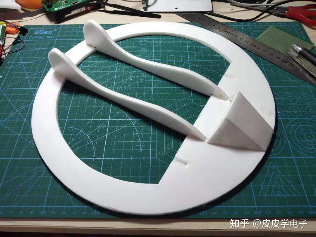
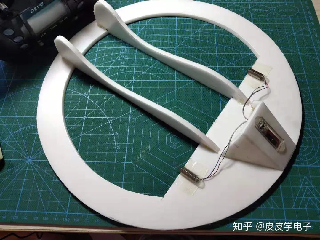
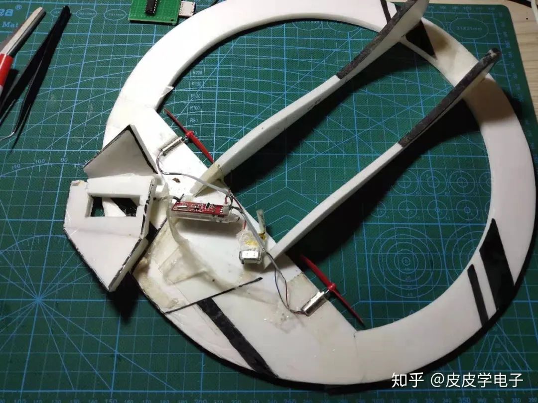
I drew the device compartment and installed it, and the flying saucer is complete!
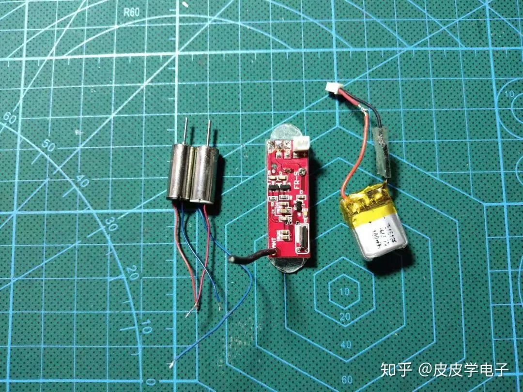
I prepared the Feixiong receiver board, battery, and two motors:
I installed them on the aircraft:
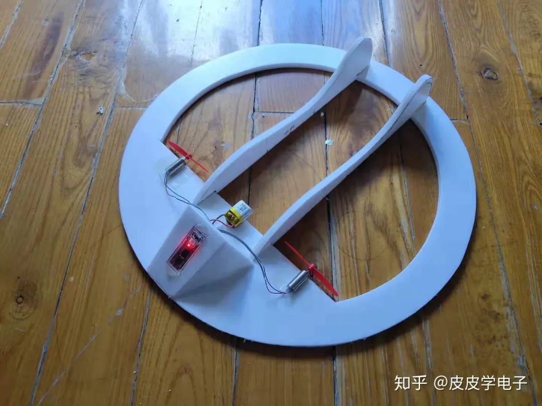
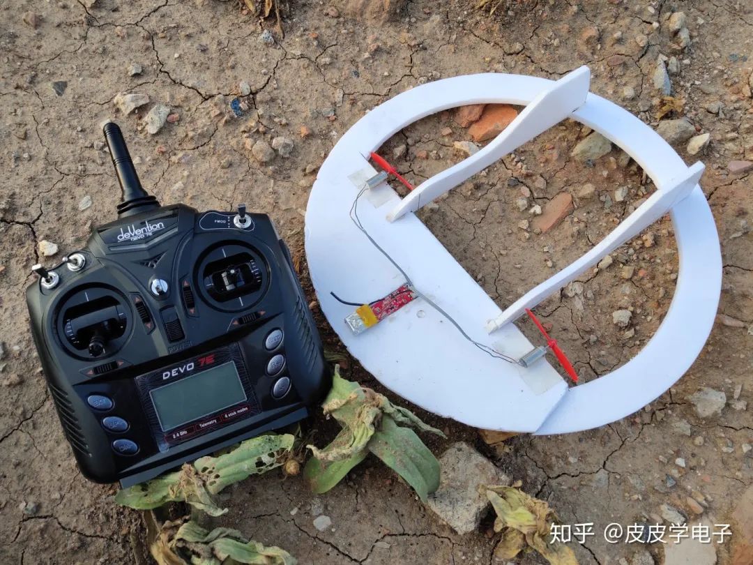
Installed the battery and propeller, ready for takeoff!
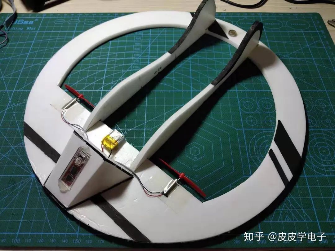
Did some painting:
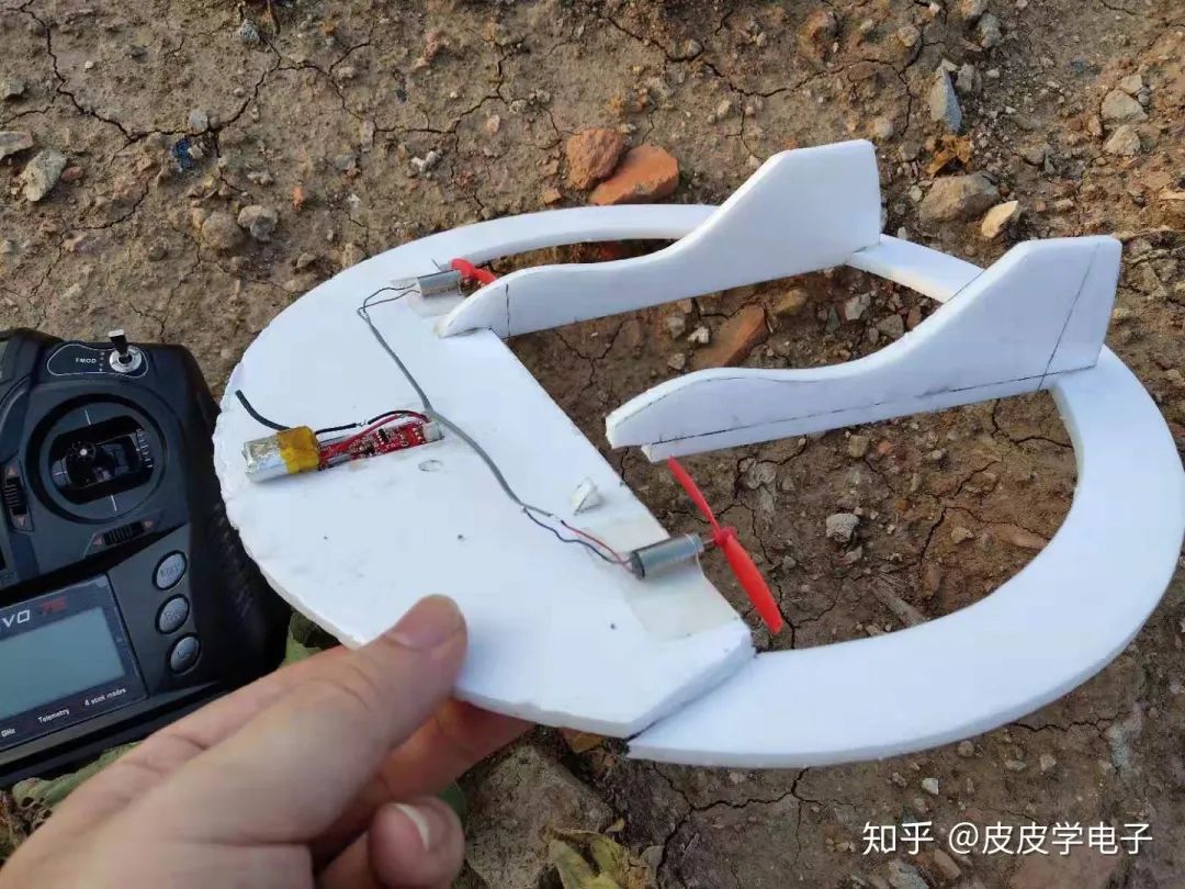
Ready to fly! The result was a crash~~
I felt the aerodynamic layout was not good, and the motor position was too far forward, so I prepared to redo it. After making a new aircraft, I took it out for a test flight:

……….. it broke
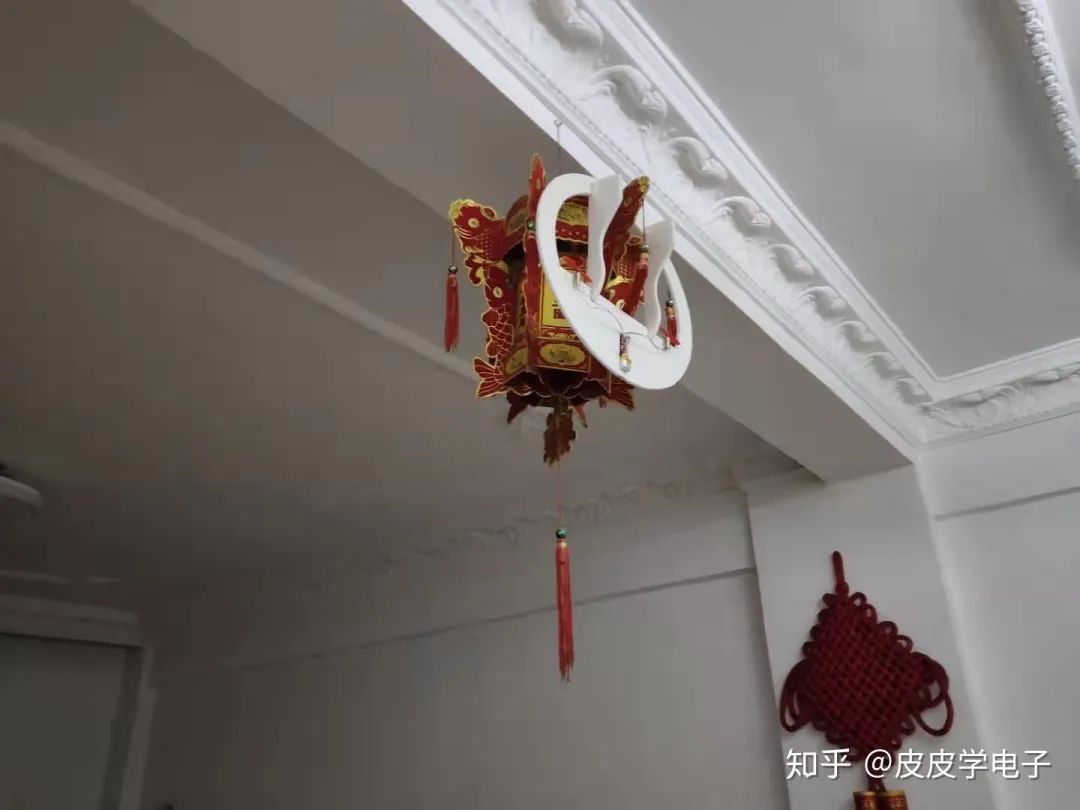
To summarize, the wind was a bit strong, the nose was a bit light, but everything else was fine. The biggest advantage of this flying saucer is its convenience for placement, for example, it can be hung on a lantern
Student Liu (Pipi Learning Electronics) DIY project collection:
Handmade Air Purifier, All Design Materials Open Source
ESP8266 + Zigbee Network Modification of Wall Switch
END
More practical project recommendations:
STM32 IoT Smart Home Project
Raspberry Pi + Compute Stick 2 Real-time Face Recognition Project
Building a Cloud Computing Platform for Embedded Development Boards
STM32 Implementing the Simplest Air Mouse
Arduino Rubik’s Cube Robot
STM32 Version of “AI Soul Painter”
Making an STM32 Electronic Photo Album
STM32 + DDS Homemade Signal Generator
Using Raspberry Pi and Web Interface to Remotely Control Home Appliances
STM32 “Cloud” Music Player
Raspberry Pi Remote Monitoring
Designing a Neon Tube Clock Based on STM32
Homemade FPGA Minimal System Board (PCB can be directly produced)
Building NAS with Raspberry Pi 4 for Easy Hard Drive Networking
ESP32 Car Hardware and Software Practical Sharing
Only 79 Lines of Code to Achieve Unlimited Creative Gesture Recognition
IoT + Electronic Ink Screen to Create Custom Display Screens
Creating a Pathfinding Robot Worth Over a Thousand Yuan for Just Dozens of Yuan
Glasses-Free 3D Holographic Display, Visual Persistence POV Project
DIY Gesture Recognition Module
Practical Small Designs That Can Be DIYed from Scratch
Raspberry Pi to Create a Smart Doorbell + Smart Lock with Video
Strangely! My Development Board Can Automatically Play Games
Homemade Breathing Machine
ESP8266 + Zigbee Network Modification of Wall Switch
Wireless Home Monitoring System
DIY Bionic Arm, A Tool to Free Your Hands
Handmade Air Purifier, All Design Materials Open Source
Tech Toy: Bluetooth Artillery That Can Be Remotely Controlled
Using ST Sensors to Create LittleBee Monitoring System, Letting Bees “Talk”
Homemade Cat Petting Device
STM32 + Raspberry Pi to Achieve 6s Rubik’s Cube Solving Robot
Recommended Reading:
Project Sharing | Electric Competition Series | Artificial Intelligence | Postgraduate Entrance Examination Essential Knowledge Points | Graduation Design | Switching Power Supply | Job SeekingWe are Nimo, the founder of Darwin, who only talks about technology and not flirting. The Darwin online education platform aims to serve professionals in the electronics industry, providing skill training videos covering popular topics in various subfields, such as embedded systems, FPGA, artificial intelligence, etc. We tailor layered learning content for different groups, such as commonly used knowledge points, disassembly assessments, electric competitions/intelligent vehicles/postgraduate entrance examinations, etc. Welcome to follow us.Official website: www.darwinlearns.comBilibili: DarwinQQ Group: Group 1: 786258064 (full) Group 2: 1057755357
Like, watch, and share three times