Source | Chip Home
In today’s rapidly evolving IoT devices and the increasing demand for remote maintenance, OTA (Over-the-Air) remote upgrade technology has become an indispensable part of smart hardware development.
OTA upgrades refer to the process of sending new firmware to devices via wireless communication methods (such as Wi-Fi, Bluetooth, NB-IoT, etc.) to achieve remote software updates. It has several significant advantages:
-
No on-site maintenance required: Saves labor costs and improves maintenance efficiency
-
Flexible iteration throughout the product lifecycle: Quickly fix bugs and add features
-
Enhances user experience: Responds to user feedback in real-time
This article will detail how to implement OTA upgrades based on the Tuya IoT platform on the classic STM32F103C8T6 microcontroller, helping your product achieve remote upgrades and maintenance more efficiently.
Of course, it is not limited to the Tuya platform; <span>the principle is the same</span>, and it can be implemented on any supported platform, including MCUs, as other MCU models are quite similar.
The core idea is very simple; <span>we divide the entire FLASH into 4 parts: bootloader, APP1, APP2, FLAG</span>.
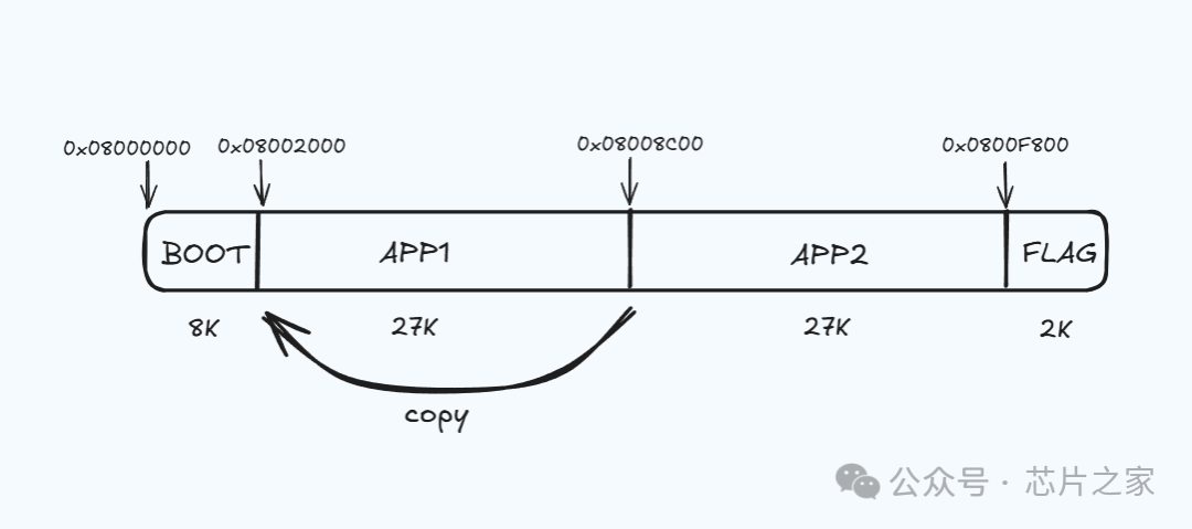 The STM32F103C8T6 has a total of 64K, with FLASH consisting of 64 pages, each 1K. The bootloader occupies 8K, the FLAG occupies 2K, and both APP1 and APP2 are 27K each, meaning our application program must not exceed 27K in size.
The bootloader is an independent firmware that, upon startup, checks the upgrade flag in the FLAG area to determine whether <span>there is new firmware to upgrade</span>. If there is, it jumps to the upgrade section, copies the APP2 part to APP1, clears the upgrade flag in the FLAG area, and then restarts, which will run the new APP1, i.e., the upgraded program.
If the power goes out halfway through the upgrade, the next restart will still copy APP2 to APP1 again because the upgrade flag has not been cleared, <span>so there is no need to worry about power outages during the upgrade causing failure to restart</span>.
When the bootloader starts, if the upgrade flag in the FLAG area is not set, it will directly start APP1.
This is the general principle; let’s look at the code:
  if(ReadFlashTest(UPFLAG) == 0x55555555)  //0x55555555
  {
     update_firmware(APP1ADDR,APP2ADDR);
     EarseFlash_1K(UPFLAG);
     WriteFlash(UPFLAG,UPFlagBuffer,4);
     printf("APP copying\r\n");
     NVIC_SystemReset();
  }
  else
  {
     Jump2APP(APP1ADDR);
  }
Copying from APP2 to APP1 involves reading a page, erasing it, and then writing:
void update_firmware(uint32_t SourceAddress,uint32_t TargetAddress)
{
  // Read, then erase, then write
  uint16_t i;
  volatile uint32_t nK ;
  nK = (TargetAddress - SourceAddress)/1024;
  for(i = 0;i < nK;i++)
  {
    memset(cBuffer,0xff,sizeof(cBuffer));
    ReadFlash(TargetAddress+i*0x0400,cBuffer,1024);
    EarseFlash_1K(SourceAddress+i*0x0400);
    WriteFlash(SourceAddress+i*0x0400,cBuffer,1024);
  }
}
The Jump2APP function facilitates the transition from the bootloader to the application code by verifying the application address, setting the stack pointer, and jumping to the application’s entry point.
void Jump2APP(uint32_t app_address)
{
  volatile uint32_t JumpAPPaddr;
if (((*(uint32_t*)app_address) &0x2FFE0000 ) == 0x20000000)
  {
    JumpAPPaddr = *(volatile uint32_t*)(app_address + 4);
    jump2app = (APP_FUNC) JumpAPPaddr;
    printf("APP jump address: %x\r\n",app_address);
    __set_MSP(*(__IO uint32_t*) app_address);
    jump2app();
  }
else{
    printf("Invalid input address\r\n");
  }
}
volatile uint32_t JumpAPPaddr; declares a variable to store the entry point address of the application (the reset handler’s address). The volatile keyword ensures that the compiler does not optimize access to this variable, as it will be read from memory.
if ((((uint32_t)app_address) & 0x2FFE0000 ) == 0x20000000) In the STM32 vector table, the first word (located at app_address) is the initial stack pointer (MSP, i.e., the main stack pointer). This checks whether the mask value indicates that the stack pointer is located in SRAM. If true, the address is considered valid, as the stack pointer of a legitimate application should be in SRAM.
JumpAPPaddr = (volatile uint32_t)(app_address + 4); app_address + 4 points to the second word in the vector table, which contains the address of the reset handler (the application’s entry point).
jump2app = (APP_FUNC) JumpAPPaddr; converts the program address to a function pointer.
__set_MSP((__IO uint32_t) app_address); __set_MSP is a CMSIS function that updates the MSP register using the value read from app_address (the application’s initial stack pointer).
jump2app(); calls the function pointer jump2app, effectively transferring control to the application’s entry point. This starts the execution of the application code.
The setup for the bootloader part has the starting address of IROM1 at 0x8000000, with a size of 0x2000.
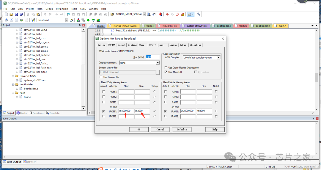 SelectErase Sectors, Reset and Run, and download.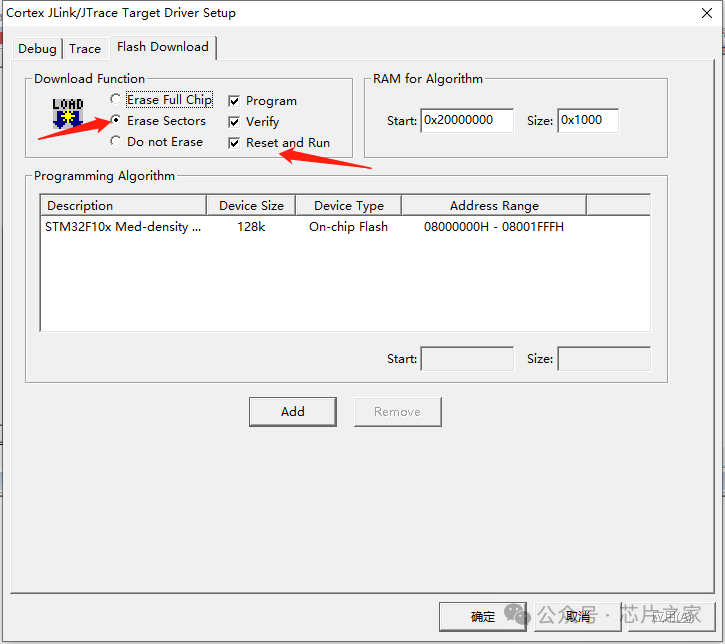
This concludes the introduction to the bootloader part.
Next, we will introduce the APP part.
The user’s code logic resides in the APP part, which requires relatively simple additional settings. We just need to <span>reset the application vector table address</span> after the code starts.
    __set_FAULTMASK(1);
    SCB->VTOR = FLASH_BASE | APP1;
    __set_FAULTMASK(0);
This is executed after the bootloader jumps to the application (e.g., via Jump2APP). It ensures that the application configures the Cortex-M CPU for its own vector table, disabling interrupts to ensure that the vector table relocation is not interrupted.
The starting address of the interrupt vector table here is 0x08002000.
It is important to note that the <span>download address of the application needs to be set to 0x8002000, with a size of 0x6C00</span>.
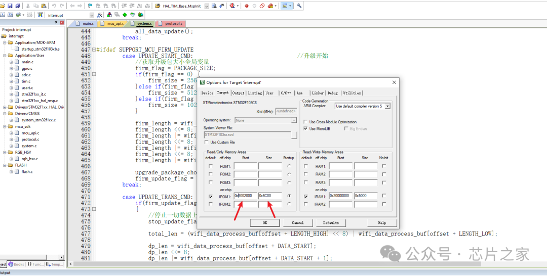
In Keil, you need to configure the compilation options fromelf.exe –bin -o “[email protected]” “#L” to generate the bin file.
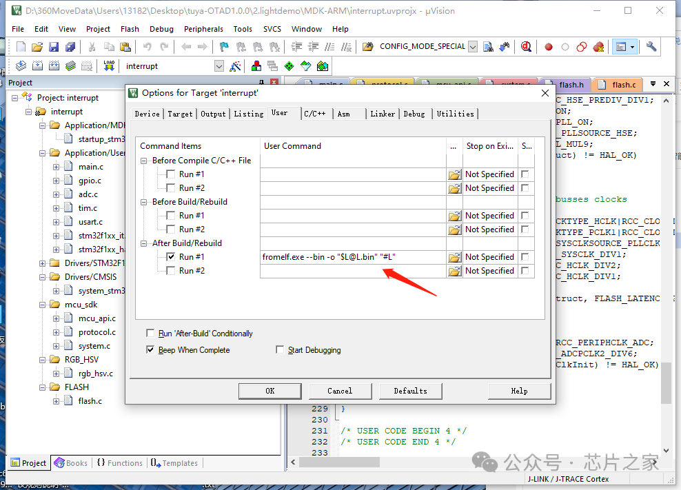
The bin file is different from the hex file; the hex file contains the programming address, while the bin file does not. Therefore, we can specify the programming address of the bin file. This way, during programming, we can directly program the APP to 0x08002000.
This means that we first need to program the bootloader file, then the app file. In subsequent mass production, we can consider merging the bootloader file and the app file into one file for programming.
Regarding how to merge, we previously published an article that can be referenced.
How to merge BootLoader and APP in MCU OTA solutions? (Click to read)
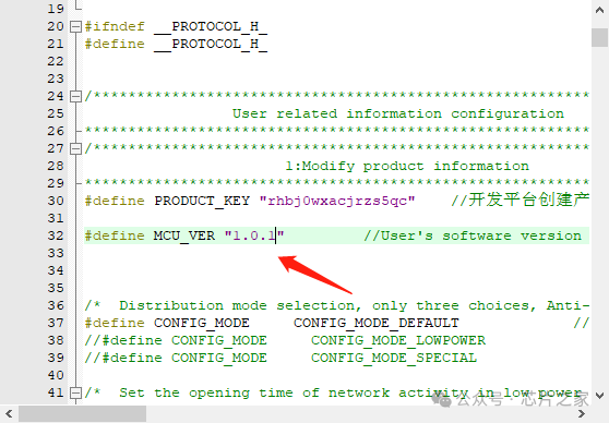
When APP1 is running, if it detects a new version number on the server, it will start executing the upgrade command, sending the new version’s bin file in packets to APP1. After APP1 receives it, it will store it in the APP2 area unchanged. After the last packet is received, it will set the upgrade flag in the FLAG area to the corresponding flag data and then restart, returning to the upgrade process described above.
#ifdef SUPPORT_MCU_FIRM_UPDATE
        case UPDATE_START_CMD:                                // Upgrade start
            // Get the size of the upgrade package global variable
            firm_flag = PACKAGE_SIZE;
            if(firm_flag == 0) {
                firm_size = 256;
            }elseif(firm_flag == 1) {
                firm_size = 512;
            }elseif(firm_flag == 2) {
                firm_size = 1024;
            }

            firm_length = wifi_data_process_buf[offset + DATA_START];
            firm_length <<= 8;
            firm_length |= wifi_data_process_buf[offset + DATA_START + 1];
            firm_length <<= 8;
            firm_length |= wifi_data_process_buf[offset + DATA_START + 2];
            firm_length <<= 8;
            firm_length |= wifi_data_process_buf[offset + DATA_START + 3];

            upgrade_package_choose(PACKAGE_SIZE);
            firm_update_flag = UPDATE_START_CMD;
        break;

        case UPDATE_TRANS_CMD:                                // Upgrade transfer
            if(firm_update_flag == UPDATE_START_CMD)
            {
                // Stop all data reporting
                stop_update_flag = ENABLE;

                total_len = (wifi_data_process_buf[offset + LENGTH_HIGH] << 8) | wifi_data_process_buf[offset + LENGTH_LOW];

                dp_len = wifi_data_process_buf[offset + DATA_START];
                dp_len <<= 8;
                dp_len |= wifi_data_process_buf[offset + DATA_START + 1];
                dp_len <<= 8;
                dp_len |= wifi_data_process_buf[offset + DATA_START + 2];
                dp_len <<= 8;
                dp_len |= wifi_data_process_buf[offset + DATA_START + 3];

                firmware_addr = (unsigned char *)wifi_data_process_buf;
                firmware_addr += (offset + DATA_START + 4);

                if((total_len == 4) && (dp_len == firm_length))
                {
                    // Last packet
                    ret = mcu_firm_update_handle(firmware_addr,dp_len,0);
                    firm_update_flag = 0;
                }
                elseif((total_len - 4) <= firm_size)
                {
                    ret = mcu_firm_update_handle(firmware_addr,dp_len,total_len - 4);
                }
                else
                {
                    firm_update_flag = 0;
                    ret = ERROR;
                }

                if(ret == SUCCESS)
                {
                    wifi_uart_write_frame(UPDATE_TRANS_CMD, MCU_SEND_VER, 0);
                }
                // Restore all data reporting
                stop_update_flag = DISABLE;
            }
        break;
#endif
This is the basic principle. Regarding the startup process of STM32 and the logic of the Tuya SDK, this article will not go into detail; everyone can look at it and understand.
The OTA code logic above has already been mass-produced and is continuously in use in actual products. Those in need can refer to it, and everyone is welcome to communicate with me in the comments section.
All source files of the code project:
Files shared via cloud disk: tuya-OTA-lightDemo1.0.0.rar
Link: https://pan.baidu.com/s/1z0EaHj3iRFYIGCbngpY5hg?pwd=8k17 Extraction code: 8k17
———— END ———— ● Column “Embedded Tools”● Column “Embedded Development”● Column “Keil Tutorials”● Selected Tutorials in Embedded ColumnFollow the public accountReply “Join Group” to join the technical exchange group according to the rules, reply “1024” to see more content.Click “Read Original” to see more shares.