
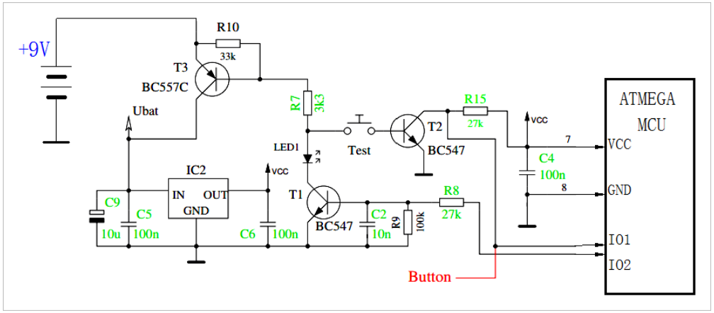
▲ Simplified Switch Circuit
Before powering the circuit, the switch “TEST” is open, and the microcontroller is not powered through VCC. At this time, the base of T1 is grounded through R9 (100k), and is in the cutoff state. The base resistor R7 of T3 is connected to Test, and T1 is also in the cutoff state, so T3 is in the cutoff state as well.
The power supply +9V is isolated by T3 and is not loaded onto the voltage regulator IC2, keeping IC2’s output VCC at a low level.
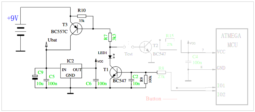
▲ Circuit in Off State
Pressing the button “TEST” starts the circuit. The base of T3 is grounded through R7, Test, and the b-e of T2, thus turning T3 on. At this point, +9V is supplied to the IC2 voltage regulator through T3. The output VCC of IC2 is supplied to the microcontroller.
After the microcontroller starts working, it outputs a high voltage through IO2, which turns T1 on through R8. Even if Test is released at this point, the base of T3 can still be grounded through R7, LED1, and T1, achieving a self-locking power-on state.
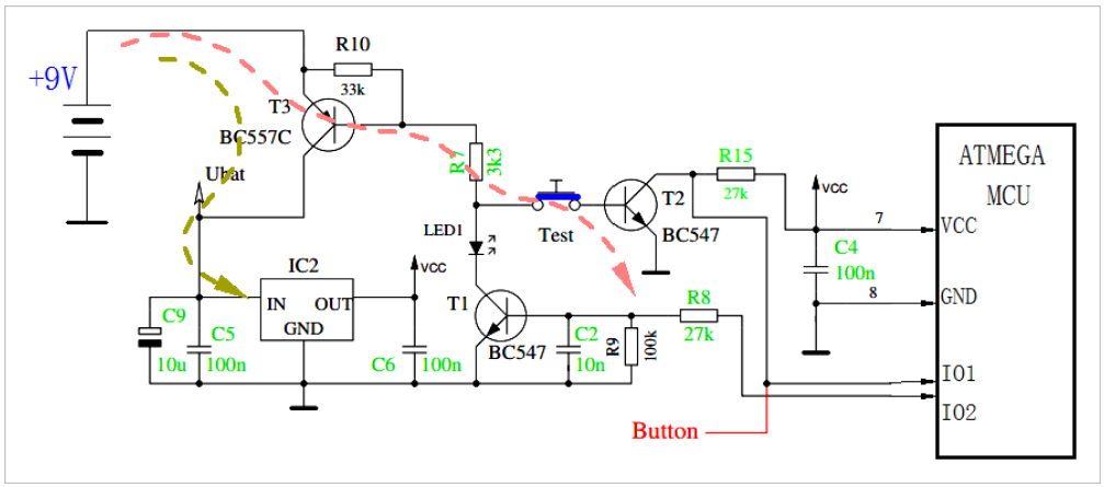
▲ Pressing TEST to Start the Circuit
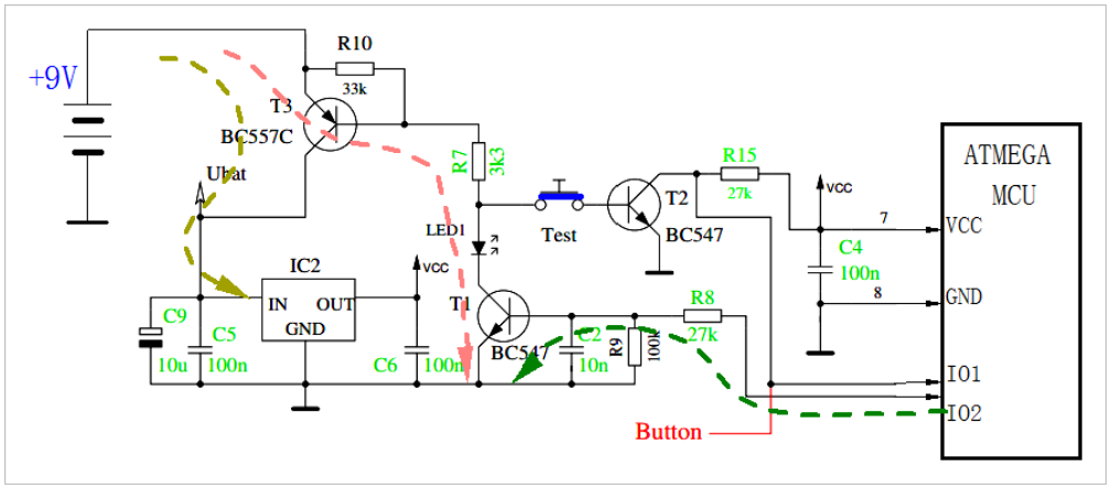
▲ After the Circuit Starts, MCU Provides Base Voltage to T1, Keeping T3 On
After this, the microcontroller software can make the IO2 port return to a low level, turning T1 off, and consequently turning T3 off.
Based on the IO1 port, the switch state of T2 can be read, thus determining whether the user has pressed the function key. After determining that the user has pressed Test, we wait until the user releases Test before setting IO2 to a low level.
The software can also implement automatic delayed power-off to reduce power consumption from the supply.
Source: TsinghuaJoking. This account maintains neutrality regarding all original and reprinted articles, and the articles are only for readers’ learning and communication. Copyright for articles, images, etc., belongs to the original authors. If there is any infringement, please contact for deletion.