
Click the blue text
Follow us
1. Introduction to Serial Communication Protocol
The concept of serial communication is very simple; it is a method of communication that sends and receives bytes bit by bit. Although serial communication is slower than parallel communication, which transmits data by bytes, it can achieve data transmission using only two wires.
Since serial communication is asynchronous, the port can send data on one line while receiving data on another line. A simple explanation is: two people are talking, one person speaks while the other listens.
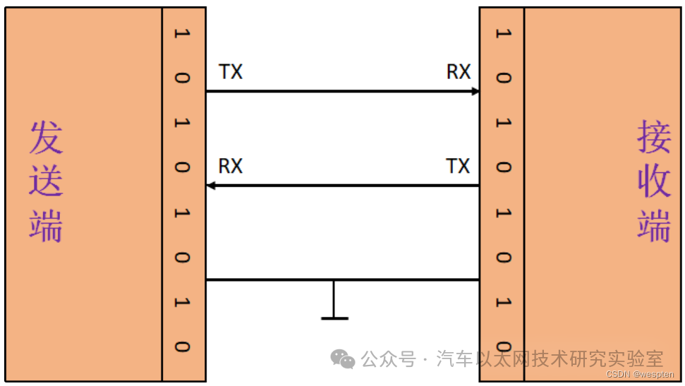
The most important parameters of serial communication are the port (com), baud rate, data bits, stop bits, and parity check. For two ports that need to communicate via serial, these parameters must match and be adhered to, which is a prerequisite for achieving serial communication.
1. Baud Rate
The baud rate refers to the modulation rate of the data signal on the carrier, represented by the number of times the carrier modulation state changes in a unit of time.
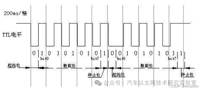
For example, a baud rate of 9600 bps means that 9600 bits are transmitted per second, which is equivalent to dividing one second into 9600 parts.
Thus, the time for each bit is 1/9600 seconds = 104.1666…us, approximately 0.1ms. Since it is divided into 9600 parts, each bit follows the next without any additional gaps. For two devices to achieve serial communication, the baud rates set for transmission and reception must be the same; otherwise, communication cannot be established.
Consistent baud rates for transmission and reception can achieve communication:

Inconsistent baud rates for transmission and reception lead to RX not receiving properly:

2. Data Structure of Serial Communication
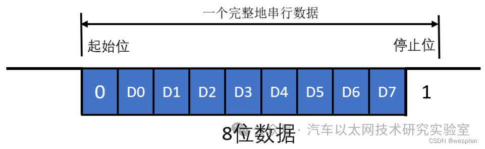
Start Bit: The start bit must be a logic low level lasting for one bit time, marking the beginning of the transmission of a character, allowing the receiver to synchronize its receiving clock with the sender’s data.
Data Bits: The data bits follow immediately after the start bit and contain the actual valid information in the communication. The number of data bits can be agreed upon by both communicating parties. During data transmission, the low bits of the character are sent first, followed by the high bits.
Parity Bit: The parity bit occupies one bit and is used for odd or even parity checks; it is not mandatory. If odd parity is used, the total number of logic high bits transmitted must be odd; if even parity is used, the total number of logic high bits must be even.
Stop Bit: The stop bit can be 1 bit, 1.5 bits, or 2 bits, and can be set by software. It must be a logic high level, marking the end of the transmission of a character.
Idle Bit: The idle bit refers to the state from the end of one character’s stop bit to the start of the next character’s start bit, indicating that the line is in an idle state, which must be filled with a high level.
2. RS232 Serial Communication Protocol
Initially, data was output as analog signals for simple process quantities, and later the RS232 interface appeared, which allows for point-to-point communication. However, this method does not support networking, leading to the development of RS485.
We know that the data transmission in serial communication consists of 0s and 1s, and in single bus, I2C, and UART, the logic 1 or logic 0 is determined by the high and low levels of a single wire. However, when the ground of this signal line is shared with other devices, it forms a common ground communication mode, which is susceptible to interference and has weak anti-interference performance. Therefore, differential communication, which supports multi-device communication and has strong anti-interference capabilities, such as RS485, has been widely used.
The most significant feature of RS485 communication is that the transmission speed can exceed 10 Mb/s, and the transmission distance can reach about 3000 meters. It is important to note that although RS485 has a high maximum speed and maximum transmission distance, the transmission speed will decrease as the distance increases, so both cannot be achieved simultaneously.
The RS232 and RS485 communication protocols are standards that we can use directly for communication without any issues. We can also define custom communication protocols, which are based on requirements and can communicate as long as they conform to standards like RS232.
The physical layer of serial communication has many standards, such as those mentioned above. Here, we mainly focus on the RS232 standard, which primarily specifies the signal usage, communication interfaces, and signal level standards.
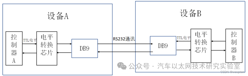
In the above communication method, the “DB9 interface” between the two communication devices is connected through serial signal lines, using the “RS232 standard” to transmit data signals. Since the RS232 level standard signals cannot be directly recognized by the controller, these signals are converted into “TTL calibrated” level signals that the controller can recognize through a “level conversion chip” to achieve communication.
The chip is connected to the PC, which typically uses the RS232 interface (9 pins). To enable direct communication between the chip and the PC’s RS232 interface, the chip’s input and output ports must also be converted to RS232 levels and cross-connected, as the level standards of the two differ:
-
Microcontroller’s level standard (TTL level): +5V represents 1, 0V represents 0;
-
RS232 level standard: +15/+13V represents 0, -15/-13V represents 1;
Therefore, serial communication between the microcontroller and the PC should follow: a level conversion circuit must be implemented between the microcontroller’s serial port and the RS232 port provided by the host computer to convert between TTL and RS232 levels.
The following diagram shows the DB9 standard serial communication interface:
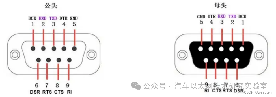
DB9 Pin Description:
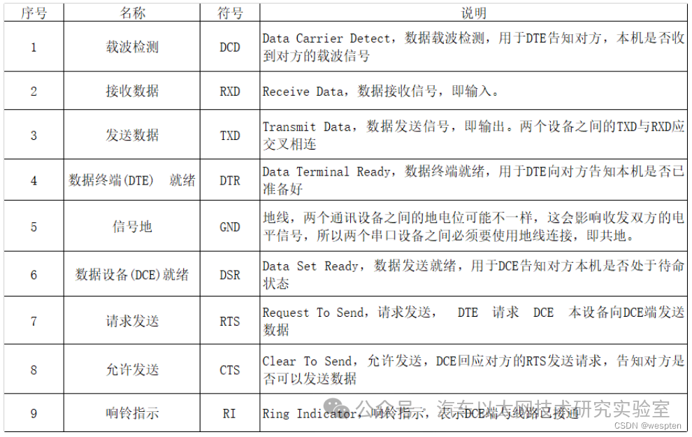
The table above shows the standard connection of the DB9 male connector on the computer side. Since the RXD and TXD signals between the two communication devices should be cross-connected, the RXD and TXD signal connections of the DB9 female connector on the modem side are generally opposite to those of the male connector. When connecting the two devices, a “straight-through” serial cable can be used.
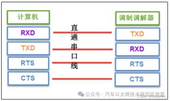
The RTS, CTS, DSR, DTR, and DCD signals in the serial cable use logic 1 to indicate that the signal is valid and logic 0 to indicate that the signal is invalid. For example, when the computer side controls the DTR signal line to logic 1, it indicates to the remote modem that the machine is ready to receive data; 0 indicates that it is not ready yet.
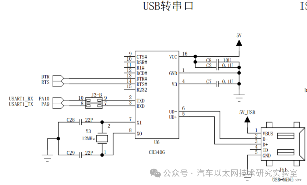
If a USB to serial converter is used, serial communication can also be achieved. The circuit diagram for USB to serial is shown below:
3. Remote Serial Port Usage
To connect serial devices on the production line, such as smart modules, instruments, PLCs, etc., to a computer in the office, directly pulling a long serial cable is not feasible due to the excessive distance. For this unbridgeable distance, we can use Ethernet, i.e., the factory’s local area network, to achieve this, as illustrated in the following diagram (using PLC connection as an example).
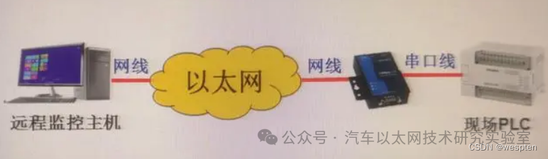
Implementation Method:
-
Add a serial server at the PLC end to achieve serial to network port functionality. The serial server has one network port and one serial port.
-
The remote computer host and the serial server are connected to the local area network via network cables, obtaining IP addresses and establishing network connections.
-
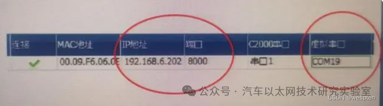
Run virtual serial port software on the computer to virtualize the serial port on the remote serial server as a local serial port. The effect is that the remote serial port can be used as if it were a local serial port. The method is to first search for the serial server over the network, find it, and then assign an available serial port number as the local serial port, as shown in the following diagram:
-
At this point, the PLC programming software on the computer can use the specified serial port number to connect to the remote PLC, making it as convenient as a local connection. The same principle applies to connecting other serial devices.
Note:
-
It is best to set the IP address of the serial server to a fixed IP to reduce communication failures caused by dynamic IP changes.
-
When applying the serial server across different network segments, the gateway address must be set correctly.
4. C# Development for Host Computer Serial Communication
For the host computer, we only need to obtain the custom communication protocol provided by a third party and program according to its content; the specific functionality is implemented by hardware engineers.
Serial communication generally has corresponding library functions, and when using and configuring the serial port, you can directly call the library functions and configure them, as shown in the following example.
First, we implement an interface, as follows:
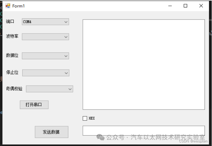
Configure serial port parameters – open the serial port:

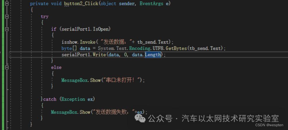
Send Data:
Receive Data:
Use asynchronous data reception.
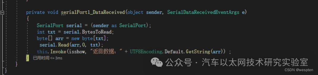
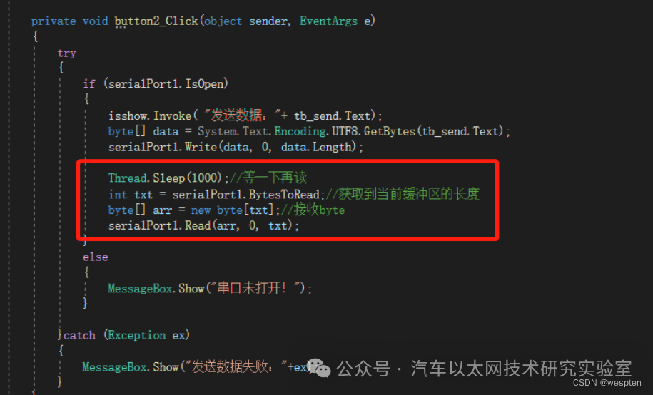
If you need to read directly after writing.
Refer to the following method:
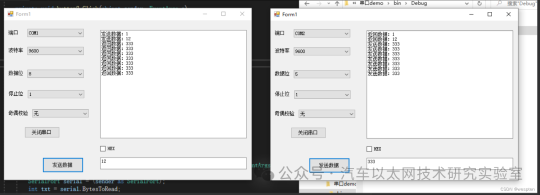
Effect Diagram:
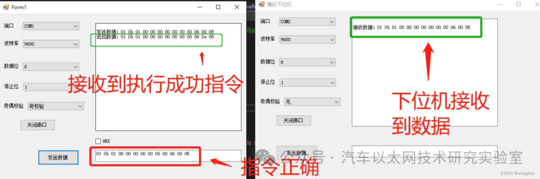
Communication based on a custom protocol (sending and receiving both use hexadecimal), first define a communication protocol.
Using RS232 for communication, set as follows:
-
Baud Rate: 9600;
-
Data Bits: 8;
-
Stop Bits: 1;
-
Parity: None;
Communication protocol content:
-
Register 1 set to 1 execute Function 1 Address 0b;
-
Register 2 set to 1 execute Function 2 Address 1b;
-
CRC Check: A value generated by operations such as AND or OR on data + address, etc. (generally, custom protocols will perform checks);
-
Start Bit: 01;
-
End Bit: 05;
-
Address Bit: 0a (determined by different registers);
-
Result Bit: 0e (success 0e, failure 00);
Example of sending: execute Function 1.

Analysis:
01 is the start bit, 0b is the address corresponding to Register 1, the data length is 8, there is no data set to 00, 06 is the CRC check value, 0e is the result bit, 05 is the end bit.
Return Success:

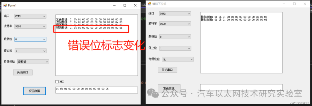
Return Failure:

A simple custom protocol, the communication process is as follows:
-
The host computer sends data
-
The slave device receives the data
-
The slave device performs CRC check; if it fails, it does not respond.
-
If the slave device’s CRC check is successful, it executes the function and provides feedback.
-
The host computer receives the data, performs CRC check; if successful, it considers the data correct; otherwise, it considers the data erroneous, and execution fails.
-
Communication is complete
Simulate register processing the commands sent by the host computer:
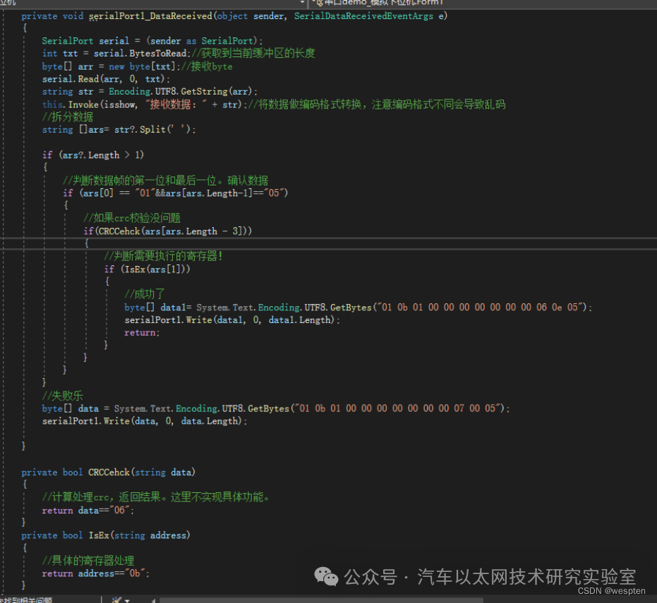
Correct command return (corresponding to the protocol):
Incorrect command return (corresponding to the protocol):


*Disclaimer: This article is original or forwarded by the author. If it inadvertently infringes on any party’s intellectual property rights, please inform us for deletion.The above images and text are sourced from the internet; if there is any infringement, please contact us promptly, and we will delete it within 24 hours.The content of the article represents the author’s personal views,and the Automotive Ethernet Technology Research Laboratory reprints it only to convey a different perspective, not representingthe Automotive Ethernet Technology Research Laboratory’s endorsement or support of that view. If there are any objections, please contact the Automotive Ethernet Technology Research Laboratory.
Original link:
https://blog.csdn.net/qq_35029061/article/details/130717375