1: Drawing Arduino Circuit Boards (Schematic Library, PCB Library, Schematic, PCB Drawing)
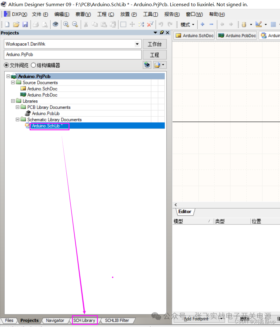
1. Drawing Schematic Library (Use existing libraries, or create your own) [SCH Library]
Here is an example
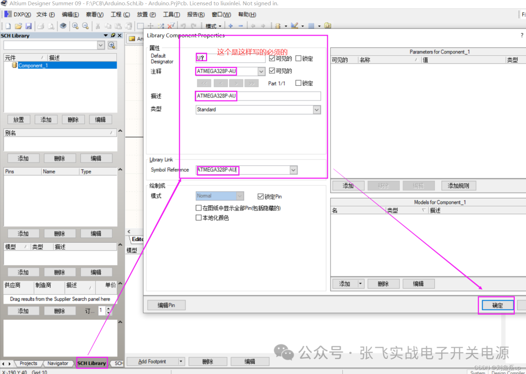
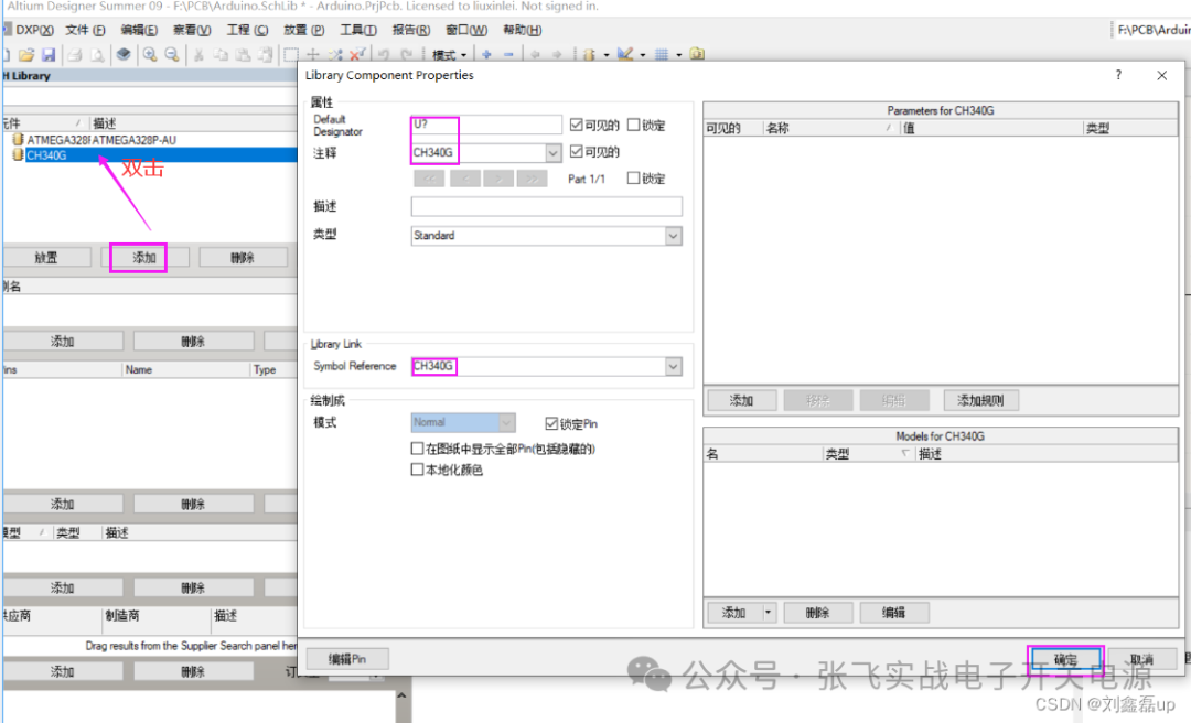
Add sub-file: Select -> Tools -> New ComponentMethod 1: Draw one by one
Below are some examples and effect images
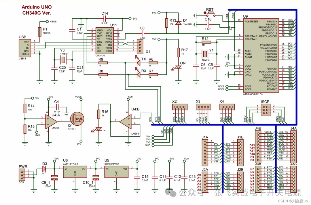
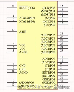
ATMEGA328P-AU
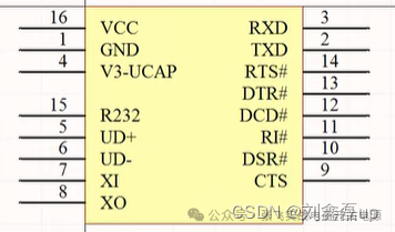
CH340G
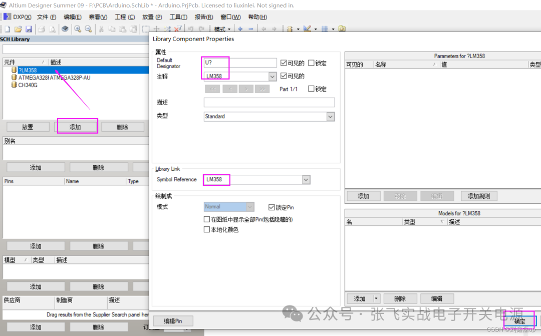
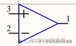
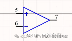
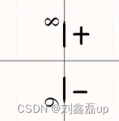
LM358
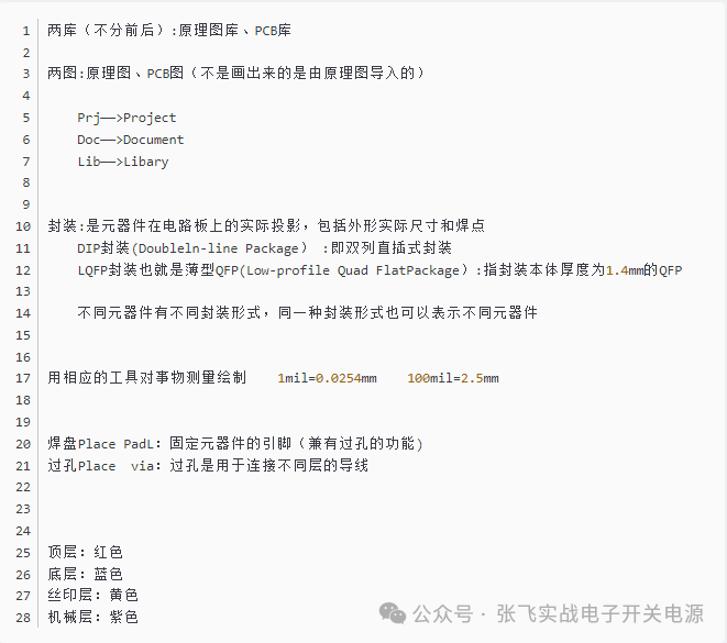
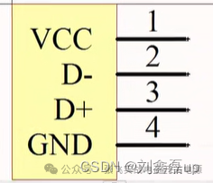
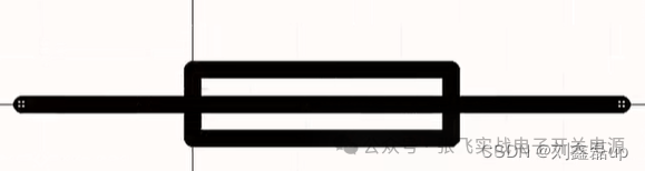
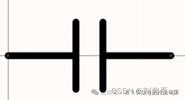
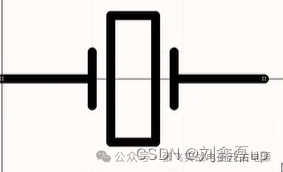
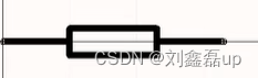
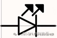
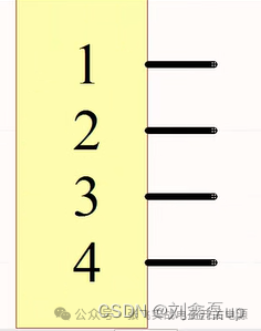
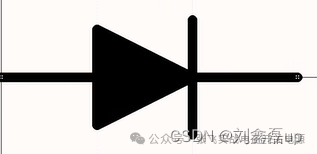
USB-B PT Ferrite Bead CAP Capacitor CRYSTAL Oscillator RES Resistor LED Light Header Pin D Diode CAP Capacitor
Method 2: Use existing libraries/third-party libraries
How to import from the existing library in the schematic library to our own library
Step 1: Click on the schematic, drag the components you want (you cannot drag from the schematic library, but you can in the schematic)
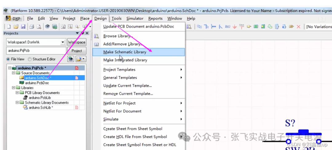
Step 2: Click Design -> Make Schematic Library to generate the schematic library -> Click OK -> A schematic library will be generated -> Then copy this component to your library

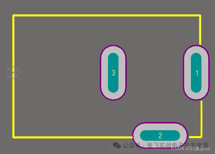
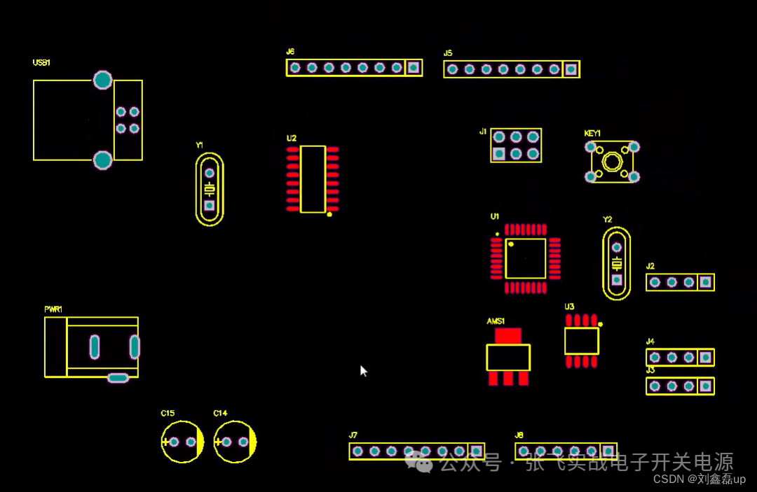
2. Drawing PCB Library
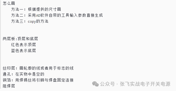
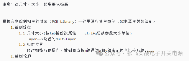
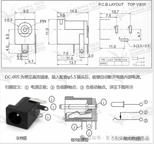
Method 1: Draw according to the provided dimensions
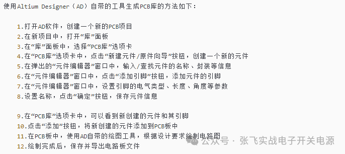
Method 2: Use the built-in tools of AD to input parameters and generate drawings
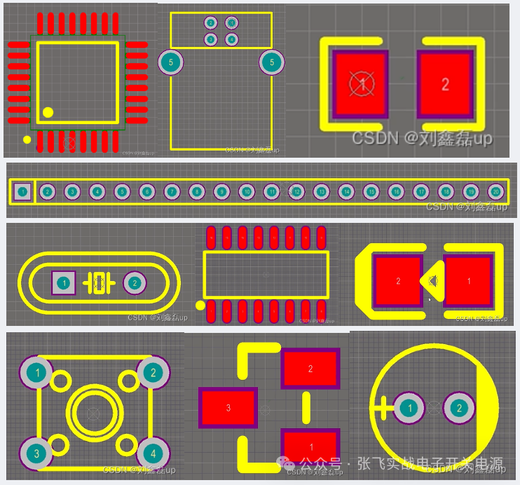
Method 3: Draw using the copy method (commonly used)
Edit ->>Set Reference ->>Place on Pin 1
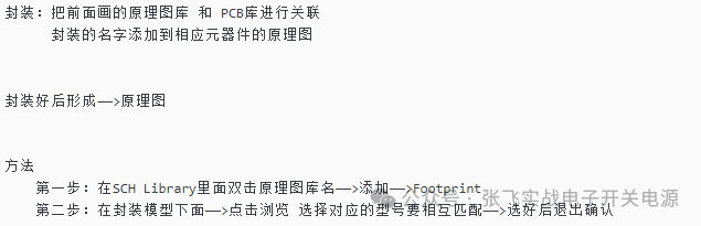
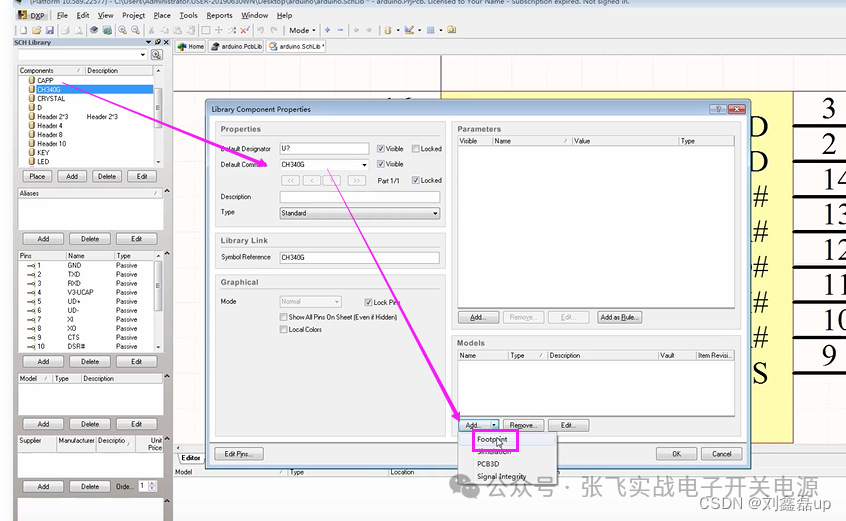
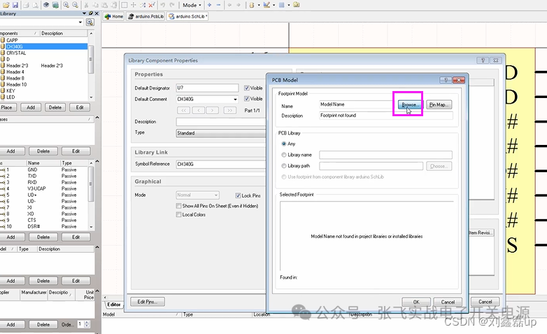
3. Package Association -> Schematic
3.1 Mutual Association

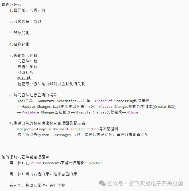
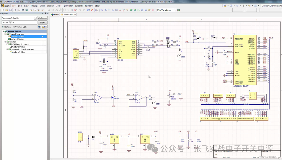
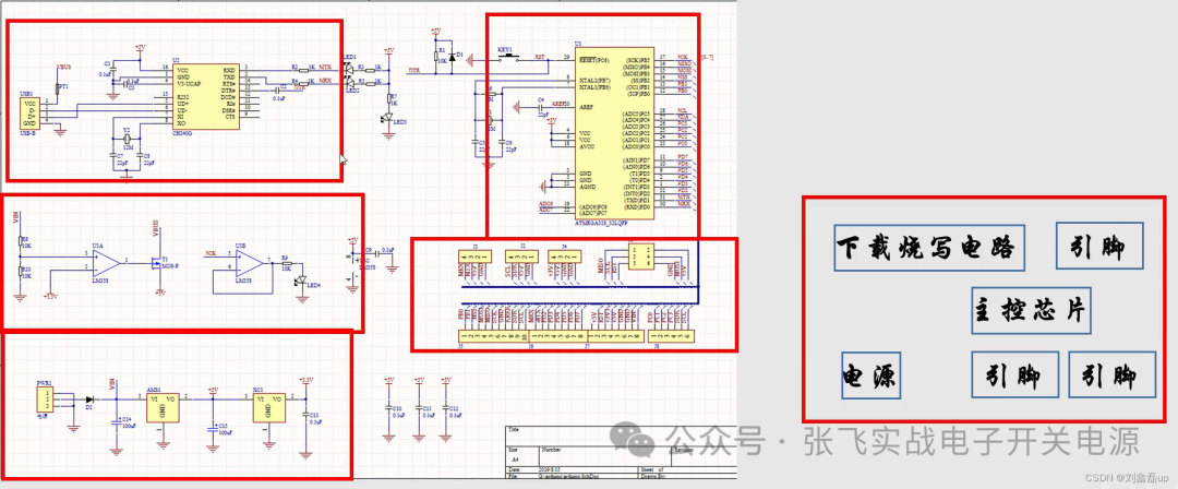
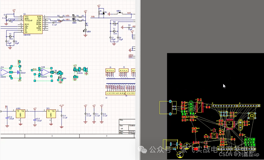
3.2 Schematic Layout Drawing: Composing Circuit Diagrams, Connecting Lines, Setting Attribute Sizes, etc.
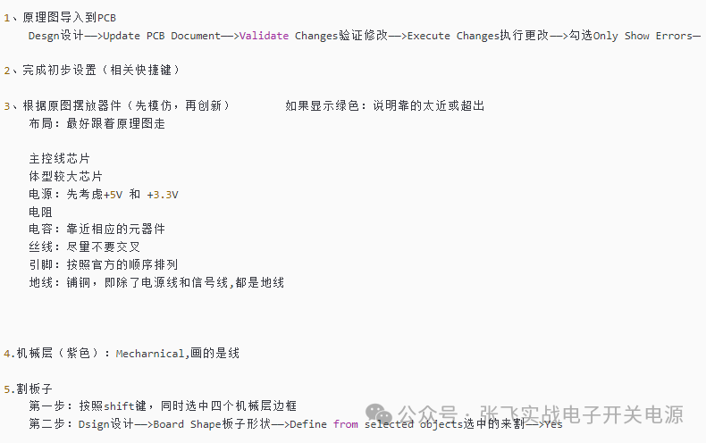
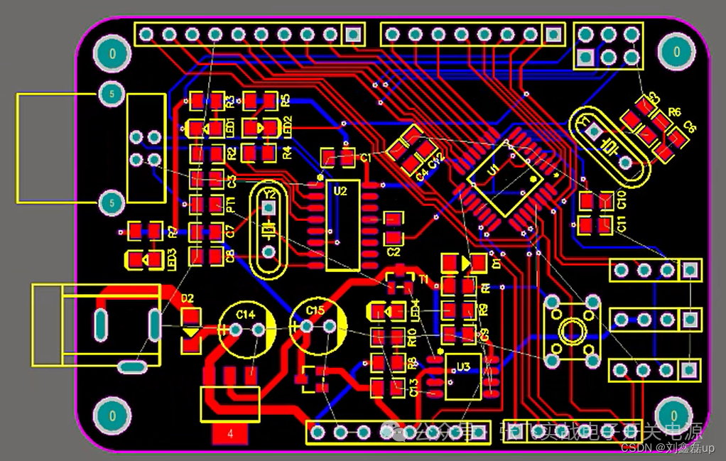
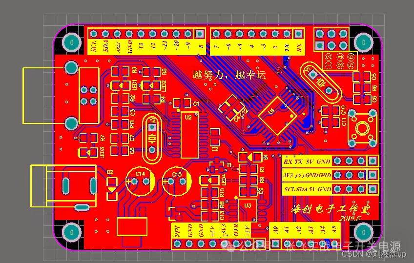
4. Import Layout Drawing -> PCB Diagram
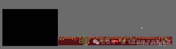
4.1 Design the Board
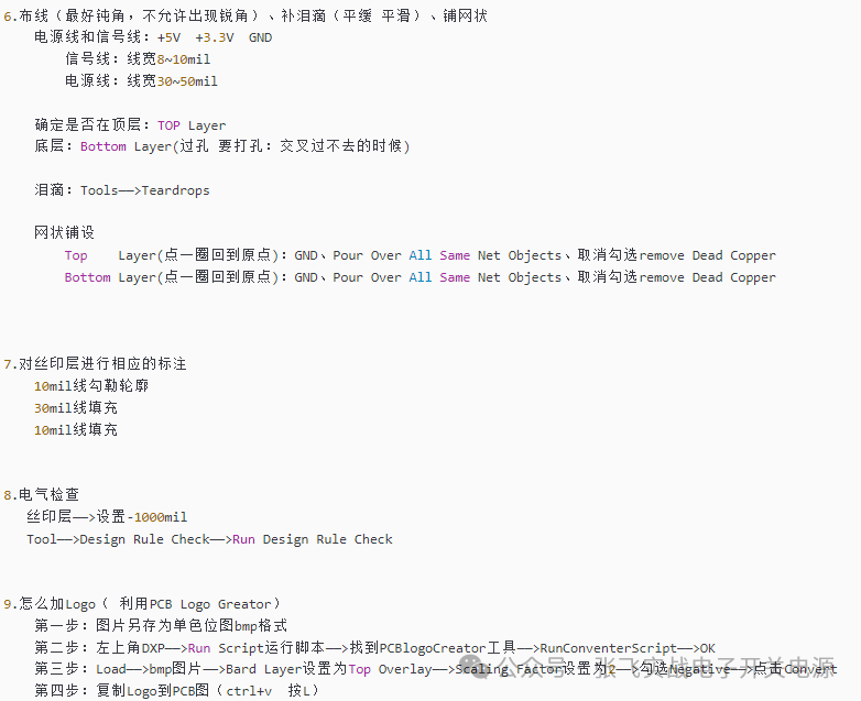
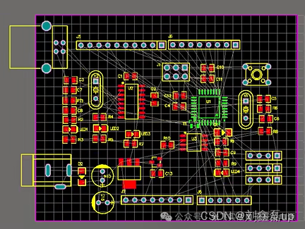
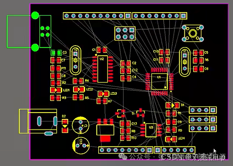
 If modifications are needed, go to copper -> remove via -> modify PCB library and schematic library -> save, update (schematic and PCB diagrams)
If this article helped you, could you give me a follow and a like?
Disclaimer: This article is reproduced from CSDN – Liu Xinlei,This account maintains neutrality regarding all original and reproduced articles, and the articles are only for readers’ learning and communication. The copyright of the articles, images, etc. belongs to the original author. If there is any infringement, please contact for deletion.