In-vehicle network communication refers to the process of data transmission and communication between various electronic control units (ECUs) within a vehicle. Modern vehicles contain multiple ECUs, each responsible for specific functions, such as vehicle control (VCU), engine control (EMS), braking system (ESC), steering system (EPS), driver assistance systems, body control systems, air conditioning systems, and entertainment systems. Communication between these ECUs allows various systems of the vehicle to work together, providing various functions and services.
The in-vehicle communication network has special requirements, such as ensuring message delivery, conflict-free messaging, minimal transmission time, low cost, electromagnetic interference resilience, as well as redundancy routing and other features. These protocols include Controller Area Network (CAN), Local Interconnect Network (LIN), Media Oriented Systems Transport (MOST), FlexRay, and the recently emerging automotive Ethernet communication due to the significant increase in data volume and the development of IT technology.
This article summarizes some key concepts and technologies related to in-vehicle network communication, specifically regarding CAN and CAN-FD:
The Controller Area Network (CAN bus) is a vehicle bus standard designed to allow microcontrollers and devices to communicate with each other without a host computer. It is a message-based protocol originally designed for multiplexing electrical wiring within vehicles to save copper wire, but it can also be used in many other contexts. For each device, data in the frame is transmitted serially, but if multiple devices transmit simultaneously, the device with the highest priority can continue transmitting while others temporarily stop. All devices, including the transmitting device, will receive these frames.
1. History of CAN
The CAN bus was developed by Robert Bosch GmbH in Germany in 1983. The protocol was first publicly released at the SAE (Society of Automotive Engineers) meeting in Detroit, Michigan in 1986. The first CAN controller chips were introduced by Intel in 1987, followed shortly by similar products from Philips. In 1991, the Mercedes-Benz W140 model became the first mass-produced vehicle to use a multiplexed wiring system based on CAN.
Bosch has released multiple versions of the CAN specification, with the latest version being CAN 2.0, published in 1991. This specification is divided into two parts: Part A applies to the standard format with an 11-bit identifier, while Part B applies to the extended format with a 29-bit identifier. CAN devices using the 11-bit identifier are typically referred to as CAN 2.0A, while those using the 29-bit identifier are referred to as CAN 2.0B.
In 1993, the International Organization for Standardization (ISO) published the CAN standard ISO 11898, which was later divided into two parts: ISO 11898-1 covers the data link layer, while ISO 11898-2 covers the physical layer for high-speed CAN. ISO 11898-3 was released later, covering the physical layer for low-speed, fault-tolerant CAN. The physical layer standards ISO 11898-2 and ISO 11898-3 are not part of the Bosch CAN 2.0 specification.
In 2012, Bosch released CAN FD 1.0, which stands for CAN with Flexible Data Rate. This specification uses a different frame format, allowing for varying data lengths and selectively switching to a faster bit rate after arbitration. CAN FD is compatible with existing CAN 2.0 networks, allowing new CAN FD devices to coexist with existing CAN devices. As of 2018, Bosch is actively promoting the expansion of the CAN standard.
The CAN bus is one of the five protocols used in the On-Board Diagnostics standard (OBD-II). Since 1996, the OBD-II standard has become mandatory for all cars and light trucks in the United States. The European Union implemented the EOBD standard for all gasoline vehicles sold since 2001 and for all diesel vehicles since 2004.
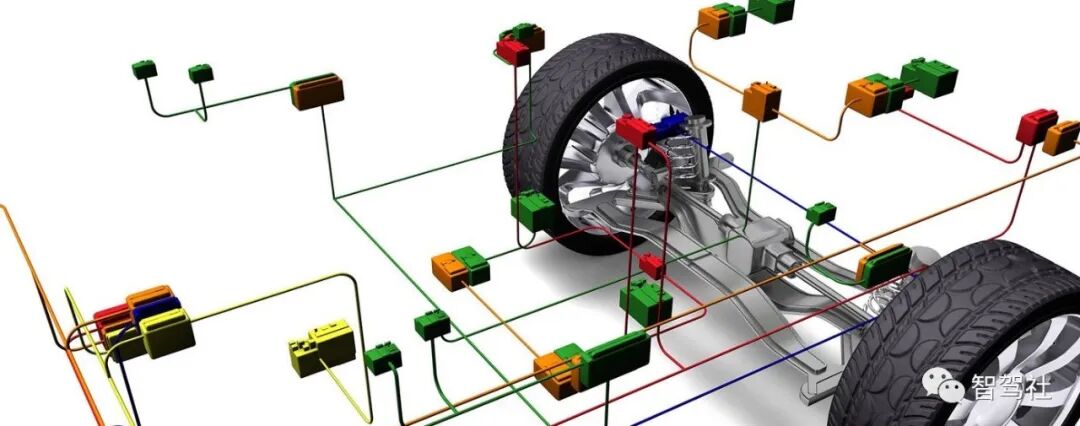
Modern vehicles may have dozens of electronic control units (ECUs) for various subsystems. The most important processors are those related to power systems and chassis control. Other ECUs are used for autonomous driving, advanced driver assistance systems (ADAS), transmissions, airbags, anti-lock braking systems (ABS), cruise control, electric power steering, audio systems, power windows, door and mirror adjustments, and battery and charging systems for hybrid/electric vehicles. Some of these form independent subsystems, but communication between others is crucial. A subsystem may need to control actuators or receive feedback from sensors. The CAN standard was designed to meet this need. A key advantage is that interconnectivity between different vehicle systems can be achieved through software, enabling a wide range of safety, economic, and convenience functions, which would increase costs and complexity if these functions were implemented using traditional automotive electrical hardwired connections.
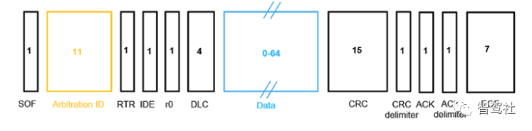
2. Basic Principles of CAN:CAN is a multi-master, multi-node, real-time serial communication protocol. It uses differential signaling to transmit data, representing digital information through the voltage difference between two wires (CAN_H and CAN_L). CAN employs very robust error detection and recovery mechanisms, such as Cyclic Redundancy Check (CRC), to ensure data reliability.3. CAN Architecture: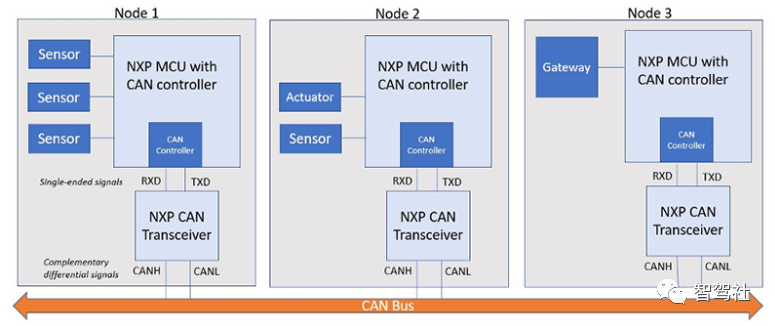 All nodes in a CAN network are connected to each other via a traditional twisted pair bus. Each node requires a microcontroller, a CAN controller (usually integrated within the microcontroller), and a CAN transceiver. Any sensor, actuator, or other control device connects to the CAN network through the microcontroller of the main processor or node. Nodes can communicate with very simple digital logic devices as well as with embedded computers or even gateways. This gateway can connect general-purpose computers, such as laptops, to devices on the CAN network via USB or Ethernet ports. The CAN transceiver handles single-ended transmit and receive signals (TXD and RXD) from the CAN controller and converts them into differential signals (referred to as CAN high (CAN-H) and CAN low (CAN-L) signals on the bus).The CAN architecture is based on a master-slave structure, with multiple nodes (slave nodes) connected to a bus controlled by a master node. Each node has a unique identifier (Identifier) used to distinguish different messages. The following are the key components of CAN:a. Node:Each electronic control unit (ECU) in a vehicle system can be a CAN node. These nodes can be engine control units, brake system control units, air conditioning system control units, etc.b. Bus:The CAN bus is the physical communication medium connecting all nodes, typically a twisted pair of wires. The CAN bus transmits data using differential signaling, providing good resistance to interference.c. Message:A CAN message is a data unit transmitted on the bus. Each message contains an identifier (Identifier), a data field (Data Field), and a control field (Control Field). The identifier is used to determine the priority and content of the message.d. Frame:A CAN message is encapsulated in a frame. CAN defines two main types of frames: Standard Frame and Extended Frame. The Standard Frame uses an 11-bit identifier, while the Extended Frame uses a 29-bit identifier.e. Master Node:The master node is responsible for controlling communication on the bus. It sends messages to the bus and processes responses from other nodes. The master node is typically the main control unit in the vehicle, such as the engine control unit.f. Slave Node:Slave nodes are those controlled by the master node. They receive commands sent from the master node and send responses or data back to the bus. Slave nodes can be control units for various vehicle subsystems.A CAN frame contains the following parts:Start of Frame (SOF):Transmits a dominant ‘0’ to inform other ECUs that a message is about to arrive.Arbitration Identifier:Used to identify the message and determine its priority. Standard CAN (CAN 2.0A) frames have an 11-bit ID, while Extended CAN (CAN 2.0B) frames have a 29-bit ID.
Remote Transmission Request (RTR):Allows an ECU to request messages from other ECUs by sending a dominant ‘1’ bit. In the case of a data frame, the RTR is a dominant ‘0’ bit.
IDE (Identifier Extension Bit):Indicates whether this is a base format frame (11-bit identifier) or an extended format frame (29-bit identifier).
r0 Bit:Reserved bit, recently known as the Flexible Data Format (FDF) bit. Indicates whether the frame is classic CAN or CAN FD.
Data Length Code (DLC):Contains the byte length of the data (0-8 bytes).
Data:Contains the actual data values, the length of which is determined by the DLC field.
Cyclic Redundancy Check (CRC):Used for error detection of data integrity.
CRC Delimiter Bit:Must be a dominant ‘1’.
Acknowledgment Bit (ACK) Slot:Confirms whether the CRC process is normal.
ACK Delimiter Bit:Must be a dominant ‘1’.
End of Frame (EOF):7 bits; the end of the frame is indicated by a dominant ‘1’.
4. CAN Communication Process:
The CAN protocol is message-based, meaning all nodes on the bus can send and receive messages, and they are always waiting for broadcast messages. While all nodes can send messages, only one message can be transmitted on the bus at any given time. Typically, the CAN controller associated with each node implements a filter to check the arbitration identifier of broadcast messages, accepting messages when the arbitration identifier is within a specific range or ignoring messages when outside that range.
The communication process includes message sending, message transmission, and message response:Message Sending: When a node needs to send a message, it encapsulates the message as a CAN frame, including the identifier and data. The frame is sent to the bus.Message Transmission: All nodes receive the message on the bus. The node that receives the message checks the identifier, and if its identifier matches the sent message, it processes the message.Message Response: After receiving a message from the master node, the slave node can send a response message, enabling two-way communication.
For example, suppose there are three nodes on the CAN bus. Node 1 sends a message with the vehicle’s current speed information, marked with ID 0x121. Node 2 accepts messages with arbitration identifiers in the range of 0x100-0x1FF. The ID of this message is within that range, so Node 2 accepts the message. Node 3 accepts messages with arbitration identifiers in the range of 0x320-0x352. The ID of this message is outside that range, so Node 3 ignores the data.
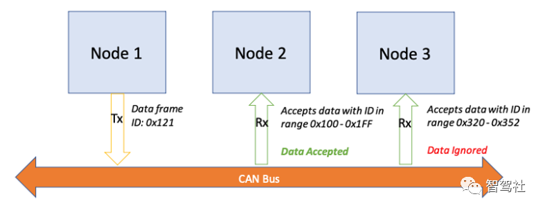
Data Transmission Flow of CAN Bus
This communication method of CAN allows real-time data exchange between different subsystems of the vehicle, achieving highly reliable and real-time automotive control. The CAN protocol uses what is known as lossless bitwise arbitration to determine the priority of messages. While each node can send and receive messages, only one message can occupy the bus at any given time. Bus access is event-driven, and multiple nodes may start transmission simultaneously. In this case, the message with the higher priority will first “own” access to the bus. The priority of the message is determined by examining the arbitration identifier bitwise—the lower the binary identifier, the higher the priority (thus, a logical ‘1’ bit is dominant over a logical ‘0’ bit). The node that owns arbitration can continue message transmission without interference from other nodes, and the message will not be delayed, corrupted, or damaged. This is known as lossless arbitration. Nodes transmitting lower-priority messages will stop transmitting when higher-priority messages are being transmitted. Once the bus is released, that node will attempt to retransmit its message.For example, if two devices attempt to transmit simultaneously on the CAN bus, as shown in the diagram below.Device A has an arbitration identifier of 11001000111.Device B has an arbitration identifier of 11011111111.Device A will win access to the bus because its arbitration identifier is lower (the 4th bit is ‘0’).Device A continues message transmission while Device B waits and attempts to transmit again when the bus is idle.
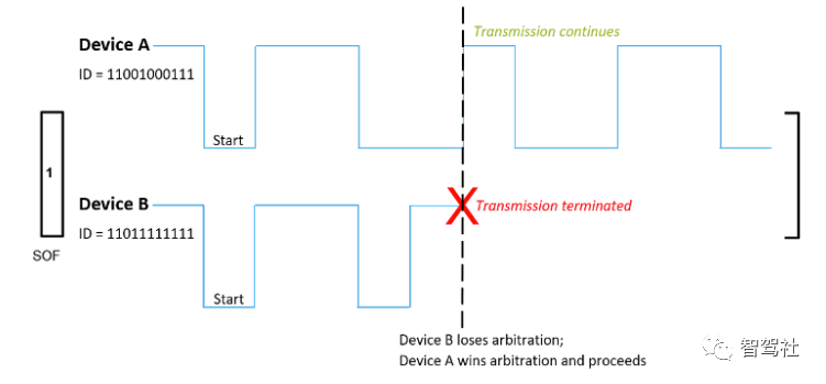
The CAN protocol uses lossless bit arbitration to determine the priority of messages. While each node can send and receive messages, only one message can occupy the bus at any given time. Bus access is event-driven, and multiple nodes may start transmission simultaneously. In this case, the message with the higher priority (the arbitration identifier with the lowest value) will first gain access to the bus. Lower-priority nodes must wait until the bus is idle to attempt transmission again.
5. Frame Types
Messages transmitted on the CAN network are also referred to as frames. CAN frames are divided into four types:
-
Data Frame: This is the most common type of frame and the only type that contains actual data. Data frames include the arbitration identifier, data field, cyclic redundancy check (CRC) field for error detection, and acknowledgment (ACK) field.
-
Remote Frame: Remote frames allow one node to request specific data from another node. There are two main differences between remote frames and data frames. First, the dominant RTR bit in the arbitration field explicitly marks the remote frame. Second, there is no data within the remote frame.
-
Error Frame: If a node detects a fault, it sends an error frame to all other nodes on the network. Nodes receiving this message will also transmit an error frame. At this point, the hardware error counter implemented in the CAN transceiver will prevent these error messages from being looped to avoid bus flooding.
-
Overload Frame: This type of frame injects a delay between data or remote frames, essentially requesting that the message be retransmitted later. As controllers have become smart enough, this type of message is no longer needed, thus saving communication on the bus.
6. Error Detection
In applications where communication loss is not permitted, reliability is crucial, and the strength of the CAN bus in this area is largely attributed to its rich error detection mechanisms. The CAN protocol integrates five error detection methods: three at the message level and two at the bit level. If a message fails in any of these methods, it will not be accepted, and the receiving node will generate an error frame. Additionally, at the message level, the CRC and ACK fields contain a checksum and delimiter bits to enforce error detection. Thirdly, there is a format check at the message level that looks for fields that must always be dominant bits. These fields include SOF, EOF, ACK delimiter, and CRC delimiter bits. If a dominant bit is detected in any of these fields, an error will be generated.
At the bit level, the transmitter monitors its own messages bit by bit. If a data bit is written to the bus and the opposite bit is read, an error will be generated. Finally, the CAN protocol uses bit stuffing rules for error detection. In the case of five consecutive bits with the same logic level, a bit of the opposite level will be inserted. This ensures that rising edges are provided to keep the network synchronized. The receiving node will remove the stuffed bits. In all fields of the frame, except for the CRC delimiter, ACK field, and EOF, bit stuffing will occur. In all fields using bit stuffing, six consecutive bits of the same polarity are considered an error as they violate the bit stuffing rule.
7. Advantages of CAN
In summary, the CAN bus has many advantages in automotive and industrial applications:
-
Low Cost: Because each ECU in the vehicle can communicate with the rest of the network through a single CAN interface rather than multiple direct signal lines, costs and architectural complexity are significantly reduced.
-
Broadcast Messages: Every node on the network can send and receive transmitted messages and can determine whether the message is relevant or should be ignored. This structure allows for modifications to the network with minimal impact.
-
Priority: Lossless bit arbitration allows the CAN protocol to determine message priority in a way that avoids delays or message corruption due to conflicts.
-
Error Detection: The CAN specification has built-in error handling mechanisms, with each node checking for transmission errors (see the description of error frames above). This is particularly beneficial in markets where reliability is crucial.
-
Robustness: The high-speed CAN bus has a high resistance to electrical interference, and some CAN controllers and receivers have industrial/extended temperature ranges, with even fault-tolerant varieties available for the harshest environments.
-
Flexibility: Because CAN is a message-based protocol, nodes on the bus do not have associated identification information. This means that nodes can be added or removed from the system without requiring any software or hardware updates.
(For those needing CAN-related tools and software, please add WeChat ID: zhijiashexiaoming)