
Current
The unit of current is Ampere (A), 1A = 1000mA
The larger the current, the more electrons pass through in the same amount of time
Common Currents
-
Microcontroller standby current: 10mA
-
Mouse and keyboard: 50mA
-
Strong flashlight: 1A
-
Laptop: 3A
-
Microwave, oven, air conditioner: 10A
-
Lightning: 10,000A
Circuit
A circuit is the pathway for current to flow. A battery is a special energy device that generates energy through chemical reactions. The positive terminal of the battery absorbs electrons, while the negative terminal sends out electrons.
Composition of an Electromagnetic Bulb
The negative terminal of the battery emits electrons, pushing electrons through the bulb back to the positive terminal of the battery
A large number of electrons passing through certain special materials will generate heat and light, which is the principle of a light bulb

Direction of Current
Note a small detail: Two hundred years ago, scientists who discovered electricity could not directly observe electrons. They guessed based on experimental phenomena, thinking that current flows from the positive terminal to the negative terminal. All physical point formulas are based on this assumption. In fact, the true direction of electron flow is opposite to that of current. However, this direction does not affect the calculation results.

Direct Current
Direct Current (DC)
-
Direct current is current that flows in one direction
-
Charge always flows in the same direction
-
DC power supplies are typically provided by batteries or other DC sources
-
DC is commonly used in small devices that require stable voltage and constant direction
-
Such as mobile phones, electric vehicles, etc.
Alternating Current
Alternating Current (AC)
-
The direction of alternating current changes over time
-
Charge flows in both positive and negative directions, alternating periodically
-
AC is typically supplied by the power grid
-
Used in various large power-consuming electrical and mechanical devices
-
Such as televisions, refrigerators, microwaves
Left is DC, right is AC

DC VS AC

Open and Closed Circuit
Open Circuit
When the switch in the circuit is in the open state
Closed Circuit
When the switch in the circuit is in the closed state
Voltage
Voltage is potential energy, measured in volts (V)
What is potential energy? It is a type of energy described by physics that indicates the energy possessed by an object
Voltage is also called potential energy. We learned about elastic potential energy in middle school. Look at this rubber band; when we stretch it, it possesses elastic potential energy, a type of energy. If I release the rubber band, the elastic potential energy converts into the kinetic energy of the paper ball’s movement.
Voltage, potential energy is the kinetic energy of electrons in the circuit, usually measured in volts (V). Voltage is an important concept in power systems; it determines the strength of current flow. The higher the voltage, the faster the electrons move, leading to a larger current. Conversely, if the voltage is low, the current will be less.
Experimental Conclusion
Increasing voltage makes LEDs brighter, and motors turn faster
After increasing voltage, a larger current will be generated, leading to a brighter LED and a faster motor. However, the voltage cannot be increased indefinitely; excessive voltage can generate too much current, causing the LED and motor to burn out.
Resistance
Voltage creates a potential difference that drives current flow
-
Series resistance, larger resistance, smaller current
-
Parallel resistance, smaller resistance, larger current
Resistance hinders the flow of current
Resistance is a fundamental concept in electronics; it refers to the extent to which current is impeded when passing through a conductor. The unit of resistance is ohm.

Ohm’s Law
Ohm’s Law is one of the fundamental laws of electricity
It describes the relationship between current and voltage. The formula for Ohm’s Law is I=U/R, where I is current, U is voltage, and R is resistance. This formula indicates that, with resistance remaining constant, voltage and current are directly proportional.

Important parameters of Ohm’s Law

Test Questions
-
In a circuit with a resistance of 2 ohms and a current of 3A, what is the voltage?
Answer: U = 3*2
-
In a circuit with two resistances of 4 ohms and 6 ohms, and a current of 2A, what is the voltage?
Answer: U = 2*10
-
In a circuit with two resistances of 3R, 4R, and 5R, with a total voltage of 12V, what is the total current in the circuit?
Answer: 12/(3+4+5)
-
In a circuit with two resistances of 3R and 6R, with a total voltage of 15V, what is the total current?
Answer: I = 15/9
-
In a circuit with three resistances of 2R, 3R, and 5R, with a total current of 5A, what is the total voltage?
Answer: U = 5*10
Ohm’s Law Calculations
Series Circuit

Current relationship: I = I1 = I2
Voltage relationship: U = U1+U2
Resistance relationship: R1+R2
Voltage division relationship: U1/R1 = U2/R2
Parallel Circuit

Current relationship: I = I1+I2
Voltage relationship: U = U1 = U2
Resistance relationship: 1/R = 1/R1+R2/1
Voltage division relationship: I1 * R1 = I2 * R2
Resistance Value Calculation
The maximum current through an LED is 20mA. If we connect a 9V battery to the LED, what size resistor should we use?

-
Determine the voltage and current of the LED, I: 20mA, U: 2.6V
-
Calculate the voltage that the resistor needs to withstand, total voltage 9V – LED’s 2.6V = 6.4V
-
According to Ohm’s Law, knowing the current is 20mA and the voltage is 6.4V, resistance = voltage/current = 6.4/0.02 = 320R
Is it Voltage or Current that Kills?

Components
Resistor
Features: Can limit the size of current. When the resistance blocks the current, electrons and energy will be presented in the form of heat, so all resistors will generate heat.

-
Common resistors, low cost, usually made of one or more metal wires wound together, can only provide a fixed resistance value.
-
Thin film resistors are made of a metal film, providing high precision resistance values, commonly used in precision instruments.
-
Photoresistor: Detects resistance based on light, such as corridor lights that turn on at night and off during the day.
-
Potentiometer: Composed of a knob or slider, can adjust resistance value, such as manually adjustable desk lamps.
-
Thermistor: A type of resistor whose resistance value changes with temperature, commonly used for temperature measurement.
-
Pressure-sensitive resistor: A resistor that changes with pressure, commonly used in pressure sensor scenarios.
-
High precision resistors are resistors with high precision, stable resistance values, and temperature coefficients.
If a wire is very long, it can also achieve resistance and generate heat; this is the principle of heating pads.

Resistor Packaging
Packaging: Look at what the resistor looks like, whether it is through-hole or surface-mount, and its size.

Resistor Nominal Value
Look at the resistance value, precision, and error, with errors of 1%, 5%, 10%. The higher the precision, the more expensive.
Resistor Rated Power
Rated power is P = I * I * R = I * U. Rated power actually limits the withstand voltage; the maximum current that the resistor can pass is fixed. The higher the rated power, the higher the withstand voltage. Exceeding the resistor’s withstand voltage will lead to its burnout.
Capacitor
Key Points:
-
Prevents voltage surges
-
No matter how high the input voltage is, the output remains unchanged
Introduction
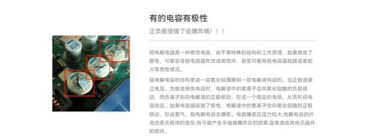
A capacitor is a container for storing electricity **(if the positive and negative terminals are reversed, it will explode)**
A capacitor is a component used to store charge and energy, consisting of two conductors and a dielectric layer, which is located between the two conductor plates.
When a capacitor is connected to a circuit, negative charge is stored on the conductor plates, generating a magnetic field between the two plates.
The unit of capacitance is Farad (F), one Farad is the capacitance of a capacitor that can store one coulomb of charge at one volt of potential. Common types of capacitors include electrolytic capacitors, ceramic capacitors, aluminum electrolytic capacitors, etc.
Different dielectrics have different charge storage capacities. The charging and discharging of a capacitor is based on electrostatic force, not involving chemical reactions, making it safer than lithium batteries.
Functions of Capacitors:
Prevent voltage surges, store energy, filter (large capacitors filter low frequencies, small capacitors filter high frequencies)
Capacitors in daily life: The power light of a charger does not turn off immediately; there is a capacitor inside that slowly releases the charge.
Inferior headphones have poor filtering and produce a lot of noise.
Types of Capacitors

-
Glass capacitor: Features high-temperature stability and low-frequency loss, commonly used in circuits under high-frequency and high-temperature environments.
-
Tantalum capacitor: Uses tantalum metal as the capacitor, featuring small size and large capacity, typically used in microcircuits.
-
Film capacitor: Uses metal film or metal foil as electrodes, featuring high precision and good stability, commonly used in high-performance electronics.
-
Aluminum electrolytic capacitor: Uses aluminum foil and electrolyte as the capacitor, featuring large capacity and low cost, commonly used in low-frequency and DC applications.
-
Mica capacitor: Uses mica as the dielectric, featuring high precision and high frequency, commonly used in precision instruments and high-frequency circuits.
-
Air capacitor: Uses air as the dielectric, featuring high precision and good stability but large size, commonly used in high-frequency and low-voltage circuits.
-
Ceramic capacitor: Uses ceramic as the dielectric, featuring small size, high-frequency characteristics, and high-temperature stability, commonly used in electronic devices.
-
Variable capacitor: A capacitor whose capacitance value can be adjusted, commonly used in radio and tuning circuits.
-
Gold foil capacitor: Uses metallized film as electrodes, featuring high precision and good stability, commonly used in high-performance electronics.
-
Supercapacitor: Also known as electrochemical capacitors, featuring high energy density, high power density, and long life, commonly used in energy storage systems and electric vehicles.
Capacitance Unit
Capacitance is a container for storing electricity
Different material dielectrics have different charge storage capacities
The unit of capacitance is Farad (F). Note: Farad is a very large unit. Other units include mF, uF, nF, pF.
-
1F (Farad) = 1000mF (millifarads)
-
1mF (millifarad) = 1000uF (microfarads)
-
1uF (microfarad) = 1000nF (nanofarads)
-
1nF (nanofarad) = 1000pF (picofarads)
Capacitor Polarity
Reversing the positive and negative terminals can cause an explosion
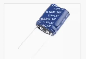
How Long Can It Run and Shine?
Formula: t=(C * V) / I
T = discharge time (in seconds)
C = capacitance (in Farads)
V = voltage of the capacitor (in volts)
I = discharge current of the capacitor (in Amperes)
C = 1.5F
V = 2.8V
I = 20mA = 0.02A
Substituting these values into the formula calculates the discharge time
t = (1.5 * 2.8) / 0.02 ≈ 210 seconds
Inductor
The Relationship Between Electricity and Magnetism
When we throw a stone into water, it creates ripples that spread outward from the stone; electricity and magnetism are similar. When current flows through a wire, it creates a magnetic field around it, like throwing a stone into water. When this magnetic field changes, it creates ripples that move surrounding electrons, generating a magnetic field; this is the principle of electromagnetic induction.
Electricity and Magnetism Can Be Converted
In motors, electric current flows through coils, generating a magnetic field that drives rotating parts (including the motor shaft); this is an application of electromagnetic induction.
Generators, in contrast, convert mechanical energy into electrical energy through rotating magnetic fields.
What is an Inductor?
Key Points:
-
Stores energy through a magnetic field
-
Prevents sudden changes in current
An inductor is an electronic component used to store and release energy in a circuit. It consists of a coil, usually made of copper wire, often with an iron core. When current flows through the inductor, it generates a magnetic field that stores energy. When the current stops flowing, the magnetic field collapses, causing the inductor to release the stored energy.
The main function of an inductor is to regulate the rate of change of current in a circuit. It can filter out high-frequency noise in the circuit, and the current across the inductor does not change suddenly, protecting other electronic components from electromagnetic interference.

Ideal Inductor Has No Energy Loss
Inductors are electromagnetic components that create magnetic fields when electricity flows, and the magnetic field resists changes in current. Unlike resistors, inductors do not dissipate energy as heat.
Inductors use enameled wire, insulated wire, etc., wound around an iron core. The unit of inductance is Henry (H).
The basic unit of inductance is H (Henry), which, like capacitance, is a very large unit. Other units include mH (millihenries), uH (microhenries), and nH (nanohenries).
The functions of inductors:
-
Inductors can be part of stabilizers in circuits, resisting changes in current to maintain stability and reliability in the circuit.

Inductors and Capacitors Form LRC Oscillator Circuits
Oscillator Circuit Principle
LRC oscillator circuits are basic oscillators consisting of inductor L, resistor R, and capacitor C, capable of producing stable AC signals. In LRC oscillator circuits, inductors and capacitors interact through resonance, causing charge to flow back and forth between the capacitor and the inductor, generating periodic current and voltage signals.
The working principle of LRC oscillators is that when the capacitor discharges, the current in the inductor begins to increase while the charge in the capacitor decreases. When the capacitor’s charge reaches 0, the current in the inductor reaches its maximum and flows back to the capacitor, causing the capacitor’s charge to start increasing. When the capacitor’s charge reaches maximum again, the inductor reaches 0 and starts to oscillate back and forth again, forming a periodic AC signal.
The frequency of LRC oscillators is determined by the values of inductor L and capacitor C, and the output signal frequency can be changed by adjusting the values of the inductor and capacitor.

Fuse/Circuit Breaker
Fuses and circuit breakers are devices used to protect circuits from overloads or electrical faults.
A fuse is an electrical component typically made of metal wire or copper foil, which disconnects current when it is overloaded to protect other components in the circuit. When the current reaches or exceeds the rated current of the fuse, the metal wire inside the fuse heats up and eventually burns out, interrupting the circuit to avoid fire hazards.
A circuit breaker is similar to a fuse but can reset and be reused. Circuit breakers usually respond to electrical faults faster than fuses, thus providing better protection for the circuit.

Important Parameters
The most important factors when purchasing components are the parameters.
Tripping speed: slow, medium, fast, super fast.
Fast tripping speed: Tripping time less than 0.001 seconds.
Rated voltage: The maximum voltage it can withstand.
Rated current: The maximum current it can withstand.
Tripping characteristics: Fast tripping is suitable for situations where high protection is required, able to cut off overload or short-circuit currents in a short time, while slow tripping is suitable for situations where protection requirements are not high, able to withstand 2-3 times the rated current for a certain time.
Buzzer
A small component that produces a beeping sound.
Sound is produced by the vibration of objects; all sound-emitting objects vibrate, and different frequencies of vibration produce different pitches.
Buzzers are divided into active buzzers that sound when powered and passive buzzers that do not sound until a high voltage signal is provided.
The audio frequency of a buzzer refers to the frequency of the sound waves it produces, measured in Hertz (Hz). The human hearing frequency range is 20-20kHz; frequencies below 20Hz are infrasound, while those above 20kHz are ultrasound. The common vibration frequency of buzzer products is 2-4kHz.

Using a Multimeter
mAh and mWh
milliampere-hours (mAh) and milliwatt-hours (mWh) are two different physical quantities representing units of electric charge and energy.

Left: 3400mAh means a current of 3400mA can discharge continuously for one hour.
Right: 12580mWh means a power output of 12.580W for one hour.
For example, if an LED operates at a current of 20mA, the left battery can work continuously for: 3400/20=170 hours.
Power calculation gives milliampere = 12580mWh / 3.7V = 3400mAh.
How Much Power Does a AA Battery Contain?
A AA battery contains 800mAh.
The voltage of a AA battery is 1.5V. 1.5V multiplied by 0.8 gives 1.2Wh, indicating that a AA battery can output 1.2Wh of power for one hour. One kilowatt-hour is 1000Wh, so 1000/1.2 ≈ 833 AA batteries = one kilowatt-hour.
Switch Circuit
A switch circuit is a basic circuit that can control the flow and output of current or voltage, simply controlling the output of load current or voltage.
Switch circuits have wide applications in modern electronic technology and are an essential part of electronic circuit design and implementation.
Using electricity to control electricity is also the core principle of computer operation.
Relay
The principle of a relay is that electricity generates magnetism, which attracts the components inside the relay to connect with another circuit.

-
Pin 1 and Pin 4 are the electromagnetic coil. Connect positive and negative terminals to generate magnetism, which connects Pin 3 with Pin 2. If no positive and negative terminals are connected to Pin 1 and Pin 4, then Pin 3 and Pin 5 will connect.
-
Pin 2 and Pin 5 are normally open switches.
-
Pin 3 and Pin 5 are normally closed switches.

Analog Circuit
-
On

-
Off

Diode
A diode is an electronic component made of two different semiconductor materials arranged to form a P-N structure, allowing current to flow in only one direction while blocking the other direction.
Because diodes only allow current to flow in one direction, they have many applications in electronics, such as making battery chargers, power adapters, and many other electronic devices.

Transistor
Working Principle of Transistors
We can compare a faucet to the circuit of a transistor; water flow is analogous to current, and the faucet switch corresponds to the control signal of the transistor.
When we turn on the faucet, water flows through the pipe. When the faucet switch is on, water flows smoothly from the faucet; when the switch is off, the water flow stops.
Similarly, when we connect the power supply in the circuit to the transistor, current will flow. When the control signal (such as a control voltage) is sent to the transistor’s base, the transistor turns on, allowing current to flow from the collector to the emitter. When the control signal disappears, the transistor turns off, stopping the current flow.

NPN and PNP Transistors
Two different switching methods made from different materials:
-
NPN transistors turn on with a high voltage at the base, allowing current to flow from the collector to the emitter, and turn off with a low voltage.
-
PNP transistors turn on with a low voltage at the base, allowing current to flow from the collector to the emitter, and turn off with a high voltage.


MOSFET
Differences between MOSFET and Transistor:
-
MOSFETs have higher voltage ratings, capable of accepting hundreds of volts.
-
MOSFETs are more energy-efficient; they are controlled by voltage, while transistors require current.

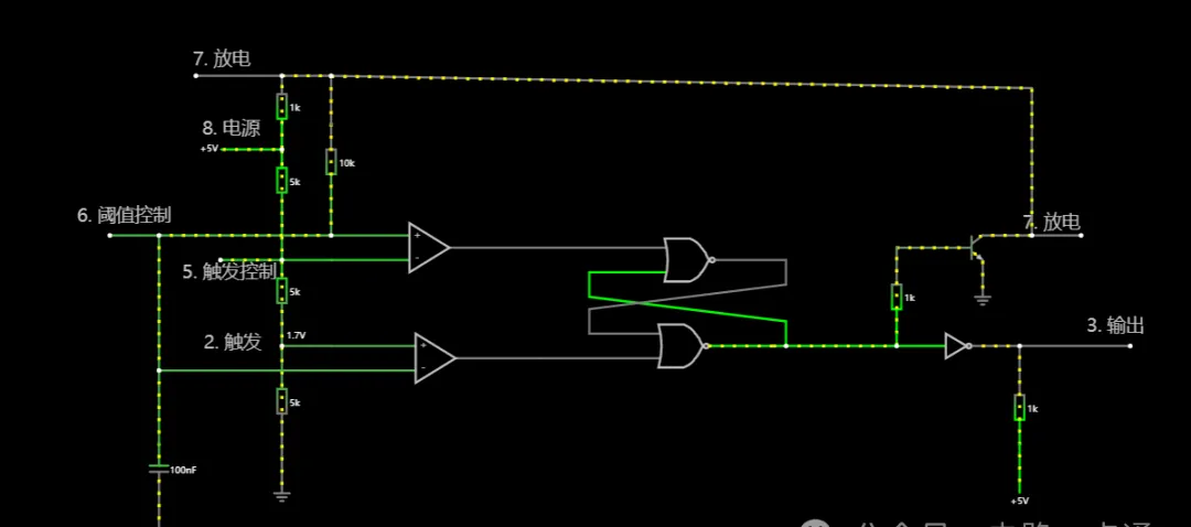
The God of Circuits: NE555
The NE555 was invented in the 1970s by the National Semiconductor Corporation and is still very popular today.
The NE555 is an integrated circuit, also known as the 555 timer, widely used in analog circuits. The NE555 has multiple applications, including square wave generators, multivibrators, pulse width modulators, timers, etc. It is a versatile, reliable, and economical circuit component used in various analog circuit designs.
The NE555 integrated circuit is one of the most important components in analog circuits, and its multiple applications make it widely used in various electronic devices.

Logical Inputs and Outputs


The effects of output and input are the same
Comparator (Operational Amplifier)
Operational amplifiers are circuit components that can process two electrical signals.
Operational amplifiers generally produce output signals by comparing the voltage levels of the input signals at their differential input ports, typically connecting two voltage signals, one being (+IN) and the other being (-IN). The operational amplifier amplifies and compares these two voltage signals’ relationships to produce an output voltage signal.
High and low output voltages need to be configured, and the larger the resistance, the smaller the impact of the operational amplifier on the circuit.

Operational Amplifier +
The output voltage value is modified within the operational amplifier component.
When the voltage at the + terminal is lower than that at the – terminal, the output is low voltage (L = low voltage, H = high voltage).

When the voltage at the + terminal is higher than that at the – terminal, the output is high voltage (L = low voltage, H = high voltage).


Inverter (NOT Gate)
High voltage becomes low voltage, low voltage becomes high voltage.
A NOT gate is a type of logic gate with one input and one output; its output is the inverse of the input, meaning when the input is high, the output is low, and vice versa. Therefore, a NOT gate is sometimes referred to as an inverter.


NOR Gate
A common component in electronic circuits.
Only when all inputs are low will it output high voltage; otherwise, it outputs low voltage in any other situation.
A NOR gate is a common type of logic gate in electronic circuits. The output signal of a NOR gate depends on the state of all input signals; as long as one input signal is high, the output signal will be low. Only when all input signals are low will the output signal be high.
In other words, a NOR gate is like a large door that only opens (outputs high voltage) when all inputs are closed (low voltage); otherwise, the door remains closed (outputs low voltage).
Flip-Flop (Latch)
A common component in electronic circuits.
-
Has two stable states, low voltage (0 state) and high voltage (1 state).
-
Can reset to 0 and 1 state based on input signal S.
-
After the input signal disappears, it can be reset to 0 or 1 state and retains that state.
-
It has memory functionality, knowing when the R terminal (reset terminal) is high voltage to reset.
-
The output voltage depends on the first input voltage, having memory functionality until the R terminal is reset by high voltage.

NE555 Schematic

Application Circuit

Analog circuit, drawing

Disclaimer:This article is reproduced from the internet, and the copyright belongs to the original author. If there are copyright issues, please contact us in time. Thank you!
