Abstract:To launch vehicles without hardware and software defects, semiconductor suppliers, original equipment manufacturers (OEMs), and tier-one OEM suppliers must work closely together to provide safety mechanisms and related safety implementation methods. Virtual Prototypes (VP) and Fault Injection (FI) are two of the various existing methods recommended by the ISO 26262 standard for verifying safety requirements. This paper presents a fault injection method process based on virtual prototypes to verify the safe execution of automotive system software. We explain our approach through a safety monitoring software example implementing a three-level electronic throttle (E-Gas) concept running on a powertrain Electronic Control Unit (ECU) model, highlighting the limitations of semiconductor and tier-one OEM virtual prototype products and future work directions.
Original Authors: Ons Mbarek, Dineshkumar Selvaraj, Romero Chica Jose Miguel, Rajagopal Shenoy, Holger Riethmueller
Original Title: Efficient Fault Injection Methods for Safety Software Testing Based on Virtual Prototypes: Application to Powertrain ECU
Compiled by: Yuan Dongdong, Yuan Xixi


01. Introduction
To comply with the ISO 26262 automotive safety standard, hardware and software components and their development processes must adhere to the ISO 26262 standard. In automotive systems, each Electronic Control Unit (ECU) consists of a set of hardware elements (e.g., microcontrollers (MCUs), application-specific integrated circuits (ASICs), sensors) on which a complex software stack runs. Due to the high complexity of such systems and the high interdependence between different software modules in an ECU stack, system software testing should begin in the early development stages. It should be executed according to a well-defined method suitable for the incremental process of software package integration and configuration. This high complexity leads to intricate system safety concepts, necessitating the development of software that activates and configures safety hardware mechanisms and responds to software errors. Using ECU virtual prototypes (VP) in conjunction with fault injection (FI) mechanisms helps accelerate the development and testing of safety-related software before real devices are available. In this paper, we propose a well-structured method for constructing fault injection (FI) test cases based on virtual prototypes. Mapping rules are defined to facilitate the transformation of existing safety-related test software and should be applied alongside the proposed method. We illustrate our approach using a Bosch MDG1 powertrain ECU virtual prototype based on the Infineon AURIX™2G microcontroller, along with a specific example of a three-level (L3) electronic throttle monitoring concept.

02. Related Work
Since the first release of the ISO 26262 automotive safety standard, a large number of fault injection techniques for software safety testing have been published. Many of these techniques target software-level simulation-based fault injection. They primarily rely on adding additional fault detectors and injectors in different software layers to perform offline instrumentation on the software. A major drawback of these methods is their invasiveness and interference with the original software under test, which has not been validated. Furthermore, most of these methods depend on additional fault injection software components at the highest application level. Therefore, their use in the incremental development and integration process of ECU software, especially in the pre-silicon phase, is limited. At the hardware level, there are various methods for simulation-based fault injection, ranging from gate-level (GL) to register-transfer level (RTL) and transaction-level modeling (TLM). In the proposed TLM techniques, non-invasive models for error injection and detection are added to the system hardware model. In practice, these techniques ensure high safety confidence in virtual prototypes, provided that these techniques are applied during the design and deployment process of the virtual prototypes. This paper elucidates this requirement with specific examples based on real industrial use cases. These techniques also target fault injection methods aimed at hardware virtual prototype validation. In contrast, the work presented in this paper aims to test software functionality on virtual prototypes. Researchers have proposed four fault injection methods based on virtual prototypes and demonstrated their application using examples based on the Infineon AURIX™ microcontroller. Overall, the research techniques lack well-defined fault injection methods. Therefore, our work supplements this by defining such a method.

03. Background
A. Electronic Throttle Monitoring Concept
The electronic throttle (E-Gas) monitoring concept is a safety concept standardized by the AKEGAS working group, applicable to gasoline and diesel ECUs. It describes the monitoring system structure that ensures the safety of automotive ECUs. Since 2013, the electronic throttle concept has complied with the ISO 26262 standard, allowing any powertrain ECU to claim compliance with the ISO 26262 standard based on it. As shown in Figure 1, the electronic throttle concept consists of three levels (L1, L2, and L3) and relies on two independent hardware components: the functional controller (FC) and the monitoring module (MM). The hardware-related monitoring (L3) within the FC includes self-checks between the FC and MM. The MM consists of an independent silicon chip (e.g., ASIC or small MCU). It contains an external watchdog for the FC, permanently using L3 query-response communication with the FC and controlling an independent disable path. L1 is the quality management software (QM), which includes the main functions of engine control. L2 monitors the performance adjustment functions of L1. The same controller (FC) typically runs L1 and L2. L3 spans the FC and the monitoring module (MC). Thus, it is a combination of software monitoring tasks and hardware monitoring structures.
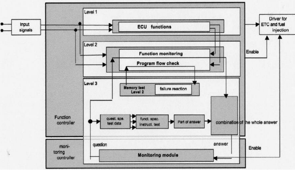
Figure 1. Block diagram of the three-level electronic gas monitoring concept
B. Challenges of Functional Safety-Compliant ECU Platforms
Figure 2 describes the hardware and software composition of the ECU. The hardware typically consists of a main controller (e.g., MCU) connected to dedicated control units (e.g., ASIC or MCU) for sensor measurement processing and actuator control. AUTOSAR-based software includes application layer (ASW), runtime environment (RTE), and basic software (BSW). Complex device drivers (CDD) provide a means to implement project-specific functions across layers, allowing direct access to RTE and ECU hardware. Complex drivers for sensors and ASICs are typically implemented in CDD while adhering to AUTOSAR port and interface specifications. AUTOSAR-based software is developed according to the safety mechanisms specified in AUTOSAR, commercially available, and ISO certified (e.g., Bosch’s CUBAS, Vector’s MICROSAR Safe, etc.). This significantly reduces their safety assessment workload. In contrast, the safety assessment of CDD software and its interference with AUTOSAR layers poses a challenge for tier-one suppliers. Therefore, not only the definition of hardware safety mechanisms but also the configuration and monitoring of these hardware mechanisms and the software’s response to detected errors should be developed according to ISO 26262 standards (e.g., electronic throttle monitoring). Typically, L3 monitoring software relies on hardware, usually developed as part of the CDD layer, while L2 and L1 software are part of the QM application layer (ASW).
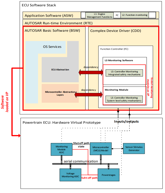
Figure 2. Hardware and software components of the powertrain ECU

04. Virtual Prototype of Powertrain MDG1 ECU
Executing automotive safety software on virtual prototypes requires modeling specific functionalities. Below, we describe our modeling approach for the virtual prototype use case from functional and safety perspectives.
A. Overview of Virtual Prototype Use Case Structure
Figure 2 shows the basic structure of our virtual prototype use case. It is based on the TLM model of the Bosch MDG1 ECU powered by the Infineon AURIX™2G microcontroller. The components of this virtual prototype come from different suppliers: the microcontroller model is provided by Infineon, while the ASIC models for the power stage and stimulus generator are developed by Robert Bosch based on software testing-driven requirements. The assembly of the complete virtual prototype is done according to project-specific layouts. The AURIX™2G microcontroller model is based on Synopsys®’s 32-bit TriCore™ fast timing model (FTM), along with a mix of loosely timed (LT) and approximately timed (AT) memory and peripheral IP models from Synopsys, Infineon, and Robert Bosch (e.g., memory). The microcontroller model achieves a good balance between timing and functional accuracy and simulation speed. Compared to RTL, the processor model’s verification achieves over 90% timing accuracy. Key IP models are co-simulated with their corresponding RTL unit test environments and calibrated according to the system RTL test platform. To run unmodified automotive software, the AURIX™ virtual prototype extends a set of ASIC LT models for external monitoring, low-side and high-side power stages, ignition/injection, and power.
B. Safety Mechanisms of the Virtual Prototype Use Case
The MDG1 ECU series is a scalable multi-core processor system designed to simplify the development of safety systems compliant with ISO 26262 standards, up to Automotive Safety Integrity Level (ASIL) -D. Based on the L3 monitoring concept, its safety concept includes hardware-integrated safety mechanisms that support checks through software, error detection hardware, or a combination of both. In the AURIX™2G microcontroller, dedicated hardware logic blocks (e.g., lockstep cores, built-in self-test (BIST), error code detection and correction (ECC)) are directly embedded in the hardware, saving the effort of developing software functional tests (e.g., instruction set and memory tests). However, the configuration of hardware-integrated safety mechanisms and error software responses still need to be protected and checked by software at runtime. At the ECU level, additional hardware safety mechanisms (e.g., watchdog timers, shutdown decoupling) should also be configured and controlled by safety software to ensure the specific product’s ASIL level. Therefore, conducting safety software testing on ECU virtual prototypes requires providing safety hardware-related functionalities in the microcontroller model related to safety software verification. For example, the Safety Management Unit (SMU) is a core module of the AURIX™2G microcontroller responsible for capturing all hardware safety errors during software execution, which needs to be modeled in the virtual prototype. Depending on the software configuration, the SMU can notify software or hardware in the event of an error or directly respond by resetting certain modules or the entire system.

05. Mapping Rules and Fault Injection Method Process
To test safety software on new hardware devices, software programmers tend to maximize the reuse of software tests used for old device variants. These tests consist of original software with additional lines of code added at specific locations to either inject faults or check error impacts and responses. In this section, we introduce the method process for performing safety software testing based on virtual prototypes.
A. Efficient Safety Software Testing Mapping Rules Based on Virtual Prototypes
As shown in Figure 3, we distinguish four different mapping rules for effectively constructing safety test scenarios suitable for running on virtual prototypes. Below, we describe them using an L3 monitoring software example.
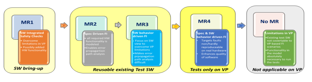
Figure 3. Classification of mapping rules and related analysis process
a) Mapping Rule 1 (MR1)
MR1 applies to the startup phase of safety software on virtual prototypes. Most periodic checks performed by such software rely on hardware and may be limited by the absence of functionalities in the virtual prototype model. A typical limitation is the stub model in the virtual prototype, where internal behaviors and/or communication side effects are not modeled. MR1 indicates that software modification is not required in the presence of alternative methods. Alternative methods include converting original software checks into alternative checks with the same verification purpose. These alternative methods intercept the real software flow at runtime and trigger monitoring checks in different ways. Figure 4 illustrates the real hardware design controlled by ADC monitoring software. This software is responsible for periodically controlling switch “sw0” by setting the test function register of the ADC module to pull down “sw0” and observing the software’s response to zero voltage. If such registers are absent in the virtual prototype, an alternative method is to set the ADC’s analog input (ANx) to zero before writing to the test function register.
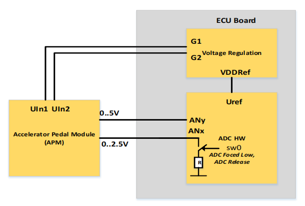
Figure 4. ADC monitoring hardware design
b) Mapping Rule 2 (MR2)
Software tests are typically implemented according to detailed specifications of safety requirements. Therefore, they encompass all intermediate steps from error creation and detection to effect checking. In the absence of limitations observed in the complete application scenario flow, it is recommended to directly map the software test code one-to-one to script-based fault injection scenarios. If this is not the case, MR3 should be considered. Figure 5 illustrates the test software flow for injecting double-bit ECC errors during program flash (PFlash) execution. Depending on the L3 monitoring software configuration, the response to this error can be handled by the kernel as a response to an interrupt received from PFlash or by the SMU, which issues an alert and causes a non-maskable interrupt (NMI). Figure 6 illustrates the hardware layout involving the aforementioned modules. Considering the configured response, this scenario can only be directly mapped one-to-one to a virtual prototype-based scenario if a write callback is present to set the DMU_HF_ECCS register in the PFlash module. Typically, status registers are read-only, such as DMU_HF_ECCS, and access to certain registers is restricted, only allowed under specific rules, such as safety protection registers. To facilitate fault injection based on virtual prototypes, it is still strongly recommended to be able to read and write registers that may be related to capturing safety violation conditions. Based on our experience, some IP model suppliers follow this recommendation, while others provide implementations based on customer requests due to the error-prone nature of this approach.
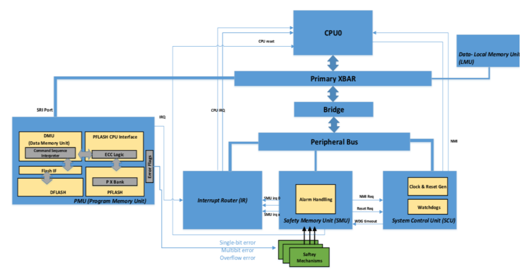
Figure 5. PMU safety test case flow
Figure 6. Interconnections between SMU, IR, CPU, and PMU in the AURIX™2G architecture
c) Mapping Rule 3 (MR3)
MR3 applies to situations where MR2 has limitations. It includes defining alternative methods to trigger error effects in different ways. This can be achieved by examining the error occurrence process and defining potential entry points for injecting faults that yield the same effects. It is generally unnecessary to execute all intermediate behaviors of the fault; more importantly, consider the parts of the fault that are directly visible to the software and respond to them. A common use case for MR3 is software testing using hardware error injection and detection logic. For example, in the AURIX™2G virtual prototype model, it is not possible to run software test cases that inject faults into the LMU safety control register to generate ECC errors. This is due to the absence of modeled error injection registers in the virtual prototype. An alternative method is to set memory control registers corresponding to the hardware detection logic for such internal ECC errors. This is also not feasible because the hardware error detection logic provided by the device does not exist in the virtual prototype. The only way to inject such faults is by triggering their direct impact on the software, including triggering the corresponding alert input signal of the SMU (see Figure 6).
d) Mapping Rule 4 (MR4)
MR4 is used to create new fault scenarios that are typically difficult to apply on real hardware, such as short circuits, open circuits, overvoltage, and undervoltage. The shutdown path testing in the electronic throttle L3 concept is a good candidate for MR4. Figure 7 illustrates this concept in the case of MDG1. MDG1 implements a decoupling mechanism between the power stage, external watchdog, and MCU controlled by a dedicated error pin set by the SMU in the event of a severe fault. It is up to the system programmer to configure which events lead to error pin events and how to recover to a safe state. These hardware safety features can enforce direct error responses, such as stopping CAN communication and shutting down the power stage. A simple way to test these error responses and the monitoring software’s dependency on other BSW packages is to pull down the error pin during CAN communication in one scenario and pull down the power stage error pin in another scenario.
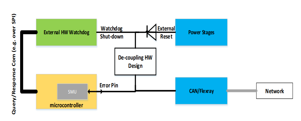
Figure 7. Shutdown path and query-response monitoring concept
e) No Mapping Rule (no MR)
Due to specific limitations of the ECU virtual prototype, it may sometimes be impossible to convert software tests into virtual prototype-based simulation tests or to conceive new purely virtual prototype-related test scenarios. A typical limitation is the absence of modeled functionalities within the virtual prototype model. For instance, while it is recommended to create overvoltage and undervoltage conditions on the virtual prototype (MR4), only a stub model of the power management system (PSM) module exists in the AURIX™2G virtual prototype, making it impossible to create such fault conditions.
B. Overall Approach for Constructing Fault Injection Testing Based on Virtual Prototypes
To construct fault models and libraries based on existing software test cases, a well-structured fault injection method based on virtual prototypes needs to be established and applied. Figure 8 illustrates the overall process of our proposed method. It consists of five sequential phases and one parallel phase. The parallel phase includes applying the previously explained mapping rules as guidelines while constructing virtual prototype-based fault injection scripts in the sequential phases. Below, we explain each sequential phase based on the example code in Figure 9, which implements the PMU fault injection test scenario based on the flow in Figure 5.
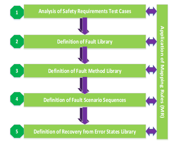
Figure 8. FI application method process
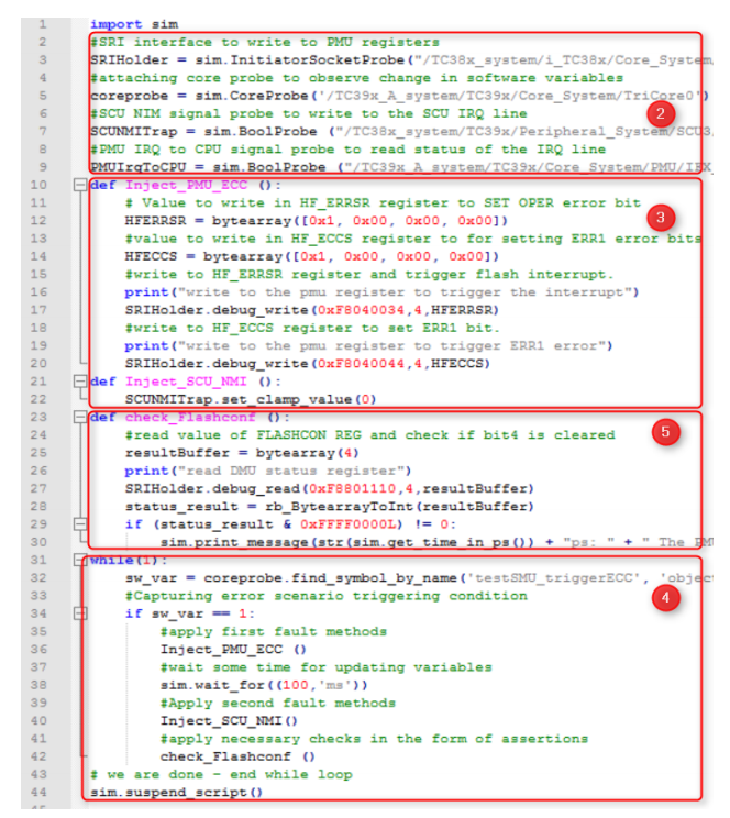
Figure 9. Application of the method in the instance
a) Step 1: Analysis of Safety Requirement Test Cases
The first step is to analyze the software test cases to identify the necessary means responsible for injecting faults in the existing implementation (e.g., registers, signals, software global variables, etc.). This requires understanding the expected software behavior that should trigger a safety error response. Mapping existing test scenarios to virtual prototypes requires applying the four mapping rules. The selection of appropriate mapping rules depends on examining the mechanisms and functionalities provided in the virtual prototype and comparing them with software response/error detection and response requirements, as previously described.
b) Step 2: Definition of Fault Library
Based on the selected mapping rules, a library specifying fault injection checkers should be defined. Fault injection checkers are responsible for either injecting faults into the target module or capturing events that determine the timing of fault injection. They are typically instances of monitoring modules attached to the hardware model interface. For example, these are the so-called “probes” in Synopsys® Virtualizer™ IDE, which can be created using a predefined Python API based on virtual prototype tools. For instance, to inject an OPER flag error in the PMU, a probe needs to be installed on the target socket of the system bus (SRI) (see Figure 9). Capturing the simulation timing point that changes the OPER flag requires creating a probe on the CPU (“coreprobe”). It monitors any changes to the “tewstSMU_triggerECC” software variable (thus indicating the start of the required monitoring task). This is an example of a dynamic event that triggers the fault injection scenario but cannot be predicted offline.
c) Step 3: Definition of Fault Model Library
This step involves defining the necessary set of callbacks that should be invoked when any probe capture event defined in Step 2 occurs. These callbacks are responsible for injecting faults by changing register or port values. They should run atomically, considering their timing processing delays and side effects. As shown in the example in Figure 9, non-invasive TLM debugging write and read interfaces that bypass the bus to directly get and set values in the model should be used to change register values. The limitations of updating register contents (e.g., read-only or safety protection registers) should be considered.
d) Step 4: Definition of Fault Scenario Sequence
Given the probes defined in Step 2 and the callbacks in Step 3, Step 4 specifies the test scenario flow (e.g., see the flow in Figure 5), starting from the trigger conditions for fault injection to the sequential calling of predefined callback functions in the correct order, and finally applying checks (Step 5) to verify specific conditions of error detection or response.
e) Step 5: Definition of Error State Recovery Library
Step 5 focuses on implementing a library for verifying the expected safety responses to injected faults. The callbacks constituting this library can then be invoked by the fault injection scenarios defined in Step 4. For example, the periodic monitoring task of L3 query-response communication between the external watchdog and MCU (see Figure 7) is accomplished by injecting faults into the responses to queries received by the external watchdog on the serial peripheral bus. The test software then checks the error software response by reading specific status registers of the MCU. Similar checks can be implemented in the virtual prototype-based fault injection scripts, ultimately checking for fault propagation in the dependency layer (see the check_Flashconf function in Figure 9).

06. Experimental Results
The aforementioned method and the fault injection error scenarios derived from original software test cases based on the four mapping rules have been applied to the AURIX™2G-based powertrain ECU virtual prototype. The main benefit is enabling system programmers to start examining issues related to safety monitoring and system responses to defects six months before real hardware is available, without being affected by hardware prototype delivery delays. Up to 40% of critical L3 software responses were tested on the virtual prototype. The remaining 60% of test cases were not applied, mainly due to the absence of functional behaviors in certain MCU sub-models and the lack of hardware safety mechanisms in the AURIX™2G model (e.g., lockstep cores, ECC logic, hardware error injection mechanisms). The flexibility provided by the virtual prototype model allows software testers to test up to six critical and important safety software error scenarios that are difficult to implement at the board level (e.g., shutdown paths, general timer module (GTM) tests) and achieve this through the application of MR4. Once the real hardware ECU is available, it ensures a rapid software startup without traps and incomplete shutdowns and resets, enabling the timely and safe release of software to OEMs with high quality.

07. Conclusion and Future Work
We presented a real industrial automotive use case for testing safety monitoring software based on virtual prototypes. We explained our fault injection method using examples based on the AURIX™2G microcontroller and the MDG1 ECU safety concept. Applying this method in the pre-silicon phase, we reported its benefits in improving software quality for release and shortening time-to-market (TTM) by quickly launching software on real ECUs. Nevertheless, we recognize the need for safety architecture exploration for the next generation of ECUs based on a well-established virtual prototype process. This will increase the testing bandwidth of safety software testing that relies on hardware. We also emphasize that virtual prototype vendors need to seriously consider the ISO 26262 certification of their tools and models. Due to the lack of virtual prototype certification and the conversion of certain test scenarios based on alternative methods, our approach is merely an efficiency measure; safety software testing must ultimately run on real silicon. Future work will focus on automating the application of mapping rules and developing a generic virtual prototype-based fault library for post-silicon virtual prototype applications, such as continuous regression testing of software variants.
Disclaimer: The views expressed in this article are for sharing and communication purposes only. The copyright and interpretation rights of the article belong to the original authors and publishing units. If there are any copyright issues, please contact [email protected], and we will address them promptly.
Related Recommendations ●●
|Functional Safety Considerations for Basic Steering Systems
|Documentation as Code in Automotive Systems/Software Engineering
|New Line Control Brake System Launched by Nexperia for Automotive Manufacturers
|AUTOSAR Methodology Analysis and Technical Implementation
|Safety Architecture for Evaluating Perception Performance in Assisted and Autonomous Driving
|ECU Hardware Foundation Design for Functional Safety of Vehicle Network Communication
|ISO 21434 Cybersecurity Engineering Method
|Using Fault Injection to Validate AUTOSAR Applications According to ISO 26262
|Achieving Functional Safety ASIL Compliance for Autonomous Driving Software Systems
|Software Architecture Design for Safety in Autonomous Driving Systems (Part 2)
|Overall Chiplet Solutions for Autonomous Vehicles (II): Communication Solutions