In software, the following image is often seen, where some information can help quickly understand the EtherCAT configuration status.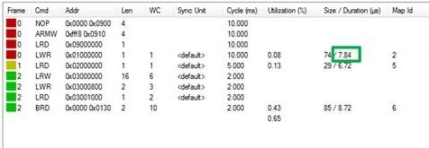 Among them,
- the “Cmd” column displays the types of EtherCAT commands.
|
Cmd |
Abbreviation |
Name |
Description |
|---|---|---|---|
|
0 |
NOP |
No Operation |
A slave ignores the command. |
|
1 |
APRD |
Auto Increment Read |
A slave increments the address. A slave writes the data it has read to the EtherCAT datagram if the address received is zero. |
|
2 |
APWR |
Auto Increment Write |
A slave increments the address. A slave writes data to a memory area if the address received is zero. |
|
3 |
APRW |
Auto Increment Read Write |
A slave increments the address. A slave writes the data it has read to the EtherCAT datagram and writes the newly acquired data to the same memory area if the received address is zero. |
|
4 |
FPRD |
Configured Address Read |
A slave writes the data it has read to the EtherCAT datagram if its slave address matches one of the addresses configured in the datagram. |
|
5 |
FPWR |
Configured Address Write |
A slave writes data to a memory area if its slave address matches one of the addresses configured in the datagram. |
|
6 |
FPRW |
Configured Address Read Write |
A slave writes the data it has read to the EtherCAT datagram and writes the newly acquired data to the same memory area if its slave address matches one of the addresses configured in the datagram. |
|
7 |
BRD |
Broadcast Read |
All slaves write a logical OR of the data from the memory area and the data from the EtherCAT datagram to the EtherCAT datagram. All slaves increment the Position field. |
|
8 |
BWR |
Broadcast Write |
All slaves write data to a memory area. All slaves increment the Position field. |
|
9 |
BRW |
Broadcast Read Write |
All slaves write a logical OR of the data from the memory area and the data from the EtherCAT datagram to the EtherCAT datagram; all slaves write data to the memory area. BRW is typically not used. All slaves increment the Position field. |
|
10 |
LRD |
Logical Memory Read |
A slave writes data it has read to the EtherCAT datagram if the address received matches one of the FMMU areas configured for reading. |
|
11 |
LWR |
Logical Memory Write |
Slaves write data to their memory area if the address received matches one of the FMMU areas configured for writing. |
|
12 |
LRW |
Logical Memory Read Write |
A slave writes data it has read to the EtherCAT datagram if the address received matches one of the FMMU areas configured for reading. Slaves write data to their memory area if the address received matches one of the FMMU areas configured for writing. |
|
13 |
ARMW |
Auto Increment Read Multiple Write |
A slave increments the Address field. A slave writes data it has read to the EtherCAT datagram when the address received is zero, otherwise it writes data to the memory area. |
- the “Addr” column provides the address of the EtherCAT slave device data area, which is used for addressing the corresponding command. If the corresponding EtherCAT command uses logical addressing (LRW, LWR, or LRD), the “Addr” column specifies the logical address.
- the “Sync Unit” column shows the name of the sync unit associated with the EtherCAT command.
- the “Cycle (ms)” column displays the cycle period (in milliseconds) for sending the transmission frame.
- the “Utilization (%)” column shows the load utilization of EtherCAT in percentage.
- the “Size” indicates the byte size of the EtherCAT frame. “Duration” indicates the time (in microseconds) required for the master to send a frame through the network card (excluding the propagation time of the frame in the network). The calculation is as follows:
|
Part of EtherCAT frame |
Size in byte |
|---|---|
|
Ethernet Header |
14 |
|
EtherCAT Header |
2 |
|
Datagram Header (10 byte/Datagram) |
4 * 10 = 40 |
|
Datagram Data (Len) |
4 + 4 + 1 + 1+ = 10 |
|
Datagram WKC (2 byte/Datagram) |
4 * 2 = 8 |
|
=> Size |
74 |
|
Ethernet FCS |
4 |
|
Ethernet Interpacket gap (12 byte) + Preamble (7 byte) + SOF (1 byte) |
20 |
|
=> Total frame size |
98 (784 bit) |
|
Duration: 784 bit / 100 Mb/s = 7.84 µs |