112023 Good News
© dream18560710



INVITATION
Embedded Systems
Design Teaching

Design of Embedded Intelligent Car Based on RTT-Thread (3)

Intelligent Car Practical Education Base
Design of Embedded Intelligent Car Based on RTT-Thread
Instructor:Gou Jun Nian



Practical Design Instructions

As part of the process assessment for the “Embedded System Design” course, the hands-on practical section involves designing and implementing an intelligent car based on RT-Thread, with the following specific requirements:
1. This section is a mandatory part of the process assessment, accounting for 20% of the total score;
2. This section is to be completed in groups (grouping organized by the instructor), with scores assessed by group;
3. The physical production of the car and a scenario-based demonstration are required;
4. Groups must complete design, integration, debugging, analysis, and summary report presentations (in video format, with a report video duration of no less than 15 minutes);
5. Specific requirements will be adjusted and explained by the relevant instructors.

1.2 Practical Operation Steps
As part of the process assessment for the “Embedded System Design” course, the hands-on practical section involves designing and implementing an intelligent car based on RT-Thread, with the following specific requirements:
1. This section is a mandatory part of the process assessment, accounting for 20% of the total score;
2. This section is to be completed in groups (grouping organized by the instructor), with scores assessed by group;
3. The physical production of the car and a scenario-based demonstration are required;
4. Groups must complete design, integration, debugging, analysis, and summary report presentations (in video format, with a report video duration of no less than 15 minutes);
5. Specific requirements will be adjusted and explained by the relevant instructors.

Design Scheme and Principles

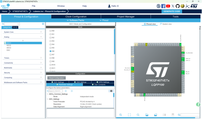
This scheme uses an ADC device to measure voltage, performing conventional BSP configuration related to ADC for the project. The STM32 chip’s analog-to-digital converter ADC1 channel 6 samples the voltage on the pin, and the terminal command reads the ADC device’s sampling value. The voltage is read through the ADC interface, and the raw ADC value is converted using the formula voltage = sampling value * reference voltage / digital value to obtain the actual voltage value. The overall design block diagram is shown in Figure 1.
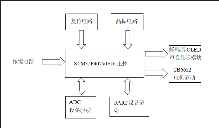
Experimental Principles:
(1) Digital-to-Analog Conversion: The ADC (Analog-to-Digital Converter) converts analog voltage signals into digital quantities for computer processing. In this experiment, the STM32’s ADC1 channel 6 collects the pin voltage, which is converted into a digital value and read by the terminal. The STM32’s ADC uses a successive approximation conversion method, comparing the input voltage with the reference voltage successively, ultimately outputting a binary digital code.
(2) BSP Configuration Principles: Configure ADC1 channel 6 through CubeMX, setting parameters such as sampling period, conversion mode, and reference voltage, generating low-level driver code to ensure correct configuration of hardware registers. In the RT-Thread system, by enabling the “ADC Device Driver” component, the system kernel can recognize the ADC hardware and provide a unified interface through the device abstraction layer.
(3) Sampling and Data Reading: The driver program starts sampling on ADC1 channel 6, and the analog voltage is sampled and held before being converted by the ADC. The converted digital value is read from the ADC data register, which is proportional to the input voltage, and the actual voltage value is calculated using the reference voltage.

Hardware Design


3.1 Hardware Selection
(1) Microcontroller: The STM32F407VGT6 microcontroller chip is used, featuring a 32-bit ARM Cortex-M4 processor core, with single-cycle MAC instructions, and up to 1MB of flash memory and 192KB of SRAM. It supports various communication interfaces such as USB OTG FS, CAN, I2C, SPI, USART, etc., allowing easy connection to various peripheral devices. Additionally, this microcontroller provides rich analog and digital peripheral functions, such as ADC, DAC, timers, PWM, and GPIO, providing strong support for implementing complex functions.
(2) Motor Driver Module: The TB6612FNG is a DC motor driver device produced by Toshiba Semiconductor, featuring a high-current MOSFET-H bridge structure with dual-channel circuit output, capable of driving 2 motors simultaneously. It has a high level of integration while providing sufficient output capability, with advantages in operational performance and energy consumption, making it an ideal motor driver device for integrated and miniaturized motor control systems.
(3) Display Module: OLED, or Organic Light Emitting Diode. OLEDs are considered the next generation of flat display technology due to their self-emitting nature, high contrast, thin thickness, wide viewing angles, fast response times, suitability for flexible panels, wide operating temperature range, and simpler construction and processing.
(4) Temperature Measurement Module: The DS18B20 single-bus digital temperature sensor is used, with a measurement range of -55℃ to 125℃, programmable for 9 to 12 bits of A/D conversion precision, achieving a temperature resolution of 0.0625℃. The CPU only requires one pin to communicate with the DS18B20, minimizing the number of CPU pins used and saving a significant amount of wiring and logic circuitry.
(5) Line Tracking Module: The XD393 photoelectric sensor module. Each XD393 provides two sets of comparators, with 1IN+, 1IN-, and 1OUT as one set, and 2IN+, 2IN-, and 2OUT as another set. Vcc connects to the power supply, and GND connects to ground. When the potential of 1IN+ is higher than that of 1IN-, 1OUT outputs a high level; otherwise, it outputs a low level. When the potential of 2IN+ is higher than that of 2IN-, 2OUT outputs a high level; otherwise, it outputs a low level. The levels of 1OUT and 2OUT can only be high (VCC) or low (0V, GND).
(6) Others: A matrix keypad composed of 16 independent keys is used to expand functional debugging.

3.2 Circuit Connection Part
(1) Capacitor filtering circuit connection schematic, as shown in Figure 2.
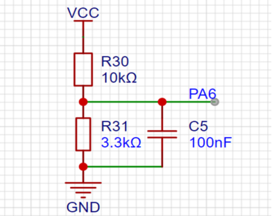
The voltage signal after voltage division filtering is connected to pin PA6 (STM32’s ADC1 channel 6).
GND: Ground signal, connected to ground.
VCC: Power supply, connected to 5V power supply.
(2) OLED display, as shown in Figure 3.
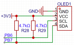
SCL: Used as a locking pin or simultaneously for I2C and SPI communication, connected to PB6 of STM32F407.
SDA: Used as the data pin for the module, for I2C communication, connected to PB7 of STM32F407.
(3) TB6612 driver circuit, as shown in Figure 4.
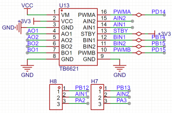
1) AINI/AIN2, BIN1/BIN2, PWMA/PWMB are control signal input terminals.
2) AO1/A02, B01/B02 are the two motor control output terminals.
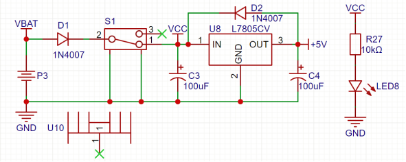
(4) Power input circuit, as shown in Figure 5.
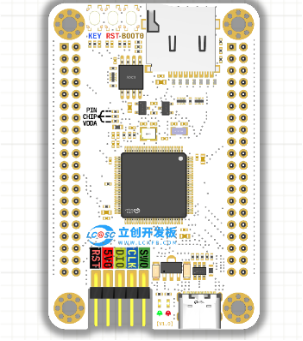
(5) STM32F407VGT6 microcontroller module, as shown in Figure 6.

3.3 Voltage Measurement Experiment – Hardware Principles
(1) Resistor voltage division sampling: Two resistors R30 and R31 form a voltage divider circuit, ensuring that the divided voltage is within the measurable range of the ADC.
(2) Capacitor filtering: The circuit uses a 100nF capacitor to filter the sampled voltage, reducing ripple interference and allowing the ADC to acquire a more stable voltage signal.
(3) ADC conversion and processing: The voltage signal after voltage division filtering is connected to pin PA6 (STM32’s ADC1 channel 6), where the internal ADC module of the microcontroller converts the analog voltage signal into a digital quantity. By calculating the value corresponding to the digital quantity, the actual voltage is obtained.
(4) Characteristics: Resolution is expressed in terms of the number of bits in binary (or decimal), typically 8, 10, 12, 16 bits, etc. It indicates the ability of the ADC to resolve the input signal; the more bits, the higher the resolution, resulting in more accurate recovery of the analog signal. Accuracy indicates the maximum error between the analog value corresponding to all digital points and the true value, which is the greatest distance the output value deviates from linearity. Conversion rate refers to the reciprocal of the time required for the A/D converter to complete one conversion from analog to digital.

3.4 Design Process
(1) Clarify collection requirements and indicators: Determine the voltage range to be collected, the input range of the ADC chip, and the ADC resolution;
(2) Voltage divider circuit design: Select and calculate resistors to ensure that the input voltage does not exceed the ADC range;
(3) Filter circuit design: Parallel a 100nF capacitor to filter out high-frequency noise and reduce signal ripple;
(4) Match with the main control chip pins: Determine the pins corresponding to the ADC channel (select PA6 of STM32);
(5) Hardware debugging and verification: Connect a known voltage, measure the divided voltage with a multimeter, and verify whether it matches the theoretical value;

Software Design


4.1 ADC Configuration

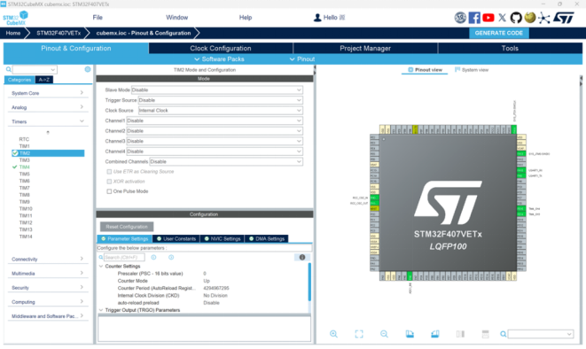
4.2 Clock Configuration
Set the clock source of TIM2 to the internal clock.

4.3 Kernel Configuration
Enable the external high-speed crystal oscillator.
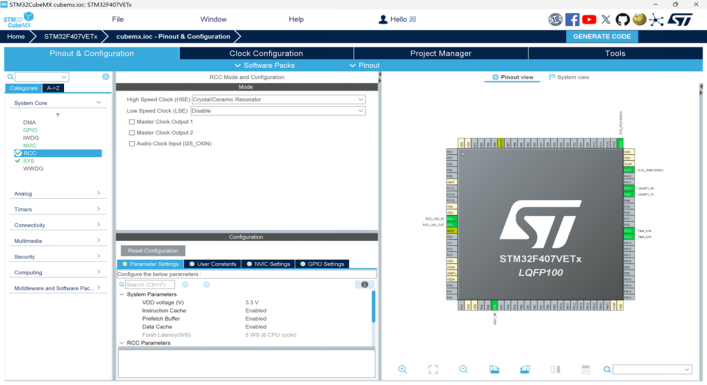
Configure the debugging interface.
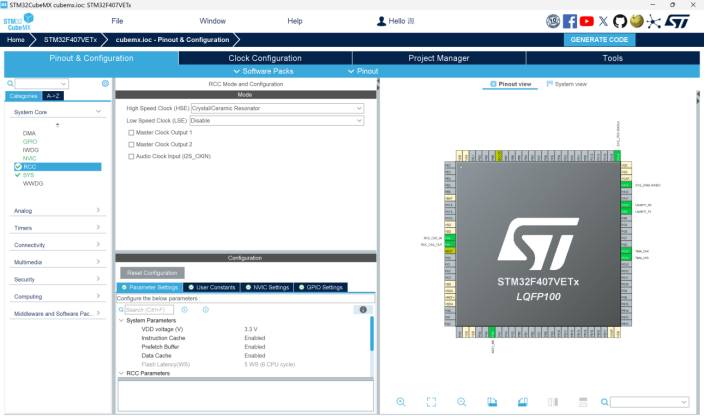

Actual Debugging and PCB Circuit Diagram


5.1 Physical Debugging Result Images
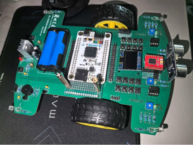

Conclusion

Through this embedded intelligent car design, I gained valuable learning experiences. Here are some key takeaways:
Hardware Design: While designing the car hardware, I realized that what seems simple is not easy to accomplish: when selecting motors, I only considered the power, forgetting whether the battery could handle it; when soldering the circuit board, I made mistakes due to shaky hands, and only after disassembling did I realize how easily the copper foil can come off.
Software Design: The most challenging part for me was multitasking scheduling: I thought it would be enough to write functions for motor control and sensor reading, but the task priorities were not set correctly, causing the car to crash while running. Later, by monitoring the task stack depth table and adjusting parameters, I understood that even millisecond-level delays in real-time systems can cause the wheels to slip.
Physical Debugging: During the debugging of the physical car, I realized that the beautifully drawn designs on paper faced many “unexpected” issues on the ground;
Report Writing: This improved my logical expression skills and laid a foundation for my future graduation design defense. Additionally, through communication with teachers and classmates, I gained valuable knowledge and advice. Writing the report not only familiarized me with the thesis format but also cultivated my rigorous work attitude.
In summary, this embedded car design not only enhanced my professional skills but also trained my logical thinking and expression abilities, greatly benefiting my future academic and career development.