

\
Recently, I have been researching microcontrollers and the security of IoT devices. Therefore, I started considering building a small home automation system. Although it is not yet complete, I would like to share how I use Raspberry Pi 2 and some other electronic components to control the lights in a room. Of course, I will not introduce the initial setup of the Raspberry Pi here, as you can find various tutorials online.
 Cautions
Before we proceed with the experiment, I think it’s necessary to remind you about the dangers of “current” in the experiment. In the worst-case scenario, you could die or burn down your house. So, please do not attempt to complete anything mentioned in this article that you do not understand, or seek help from an experienced electrician while making it.
Alright, let’s start DIY!
Preparation for the Experiment
Hardware Requirements
1. Raspberry Pi 2 (or any model with 5V output power)
2. USB wireless dongle
3. 8-channel relay
4. Some Female-Female jumper wires (40 PCS FEMALE TO FEMALE JUMPER WIRES)
5. Lamp socket wiring
(All the above hardware is available for sale on Taobao)
Other Requirements
1. Basic understanding of Python or any other language (I will be using Python)
2. Basic understanding of Linux systems
3. Focus and dedication
Process Requirements
First, connect to the Raspberry Pi via ssh and install “apache” and “php5”:

You will need to install the Python GPIO library to control the GPIO pins of the Raspberry Pi:

Understanding the Components
Now, before we continue with the production, you need to understand the electronic components we will be using.
1. Relay
A relay is an electrical device that uses very low voltage input to control high voltage electricity. It consists of a closed circuit with a metal rod wound with a coil and two small metal nodes. One node is fixed, and the other is movable. Whenever current flows through the coil, it generates a magnetic field that attracts the movable node towards the static node, completing the circuit. By supplying a small voltage to the coil, we can complete the high voltage circuit. At the same time, the static node is not physically connected to the coil, so if something goes wrong, the microcontroller-driven coil rarely fails.
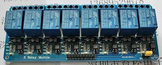
In the experiment, I used an 8-channel relay, which can control 8 devices simultaneously. You can choose your relay or relay board, but make sure you operate within the relay’s rated voltage to avoid any accidents.
2. Jumper Wires
Jumper wires are the simple connecting wires we use to link the Raspberry Pi GPIO pins to the relay.
3. Raspberry Pi 2
We use the Raspberry Pi 2 as a microcontroller to manipulate the relay. It has 40 GPIO (General Purpose Input/Output) pins. You can see the layout of these pins below, and we will use these interfaces to power the relay and control the switches.

Connecting the Circuit
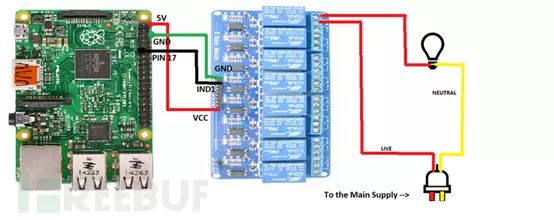
The circuit is very simple. We will connect the GPIO pins to the relay board. First, connect the “GND” on the relay board to any “GND” on the Raspberry Pi. Then link the relay’s “IND1” to GPIO PIN 17, where we will use GPIO PIN 17 as an output to control the first relay. Finally, connect the relay’s “VCC” to the Raspberry Pi’s “5V” GPIO pin. Let’s set it up simply and directly:

Now we have reached the most challenging part, we need to connect the relay to the lamp socket that powers the main circuit. However, I would like to first introduce a simple operation to turn the light on and off using a DC power supply.
We usually connect two wires to the bulb to provide current supply. One wire is the “neutral” wire, and the other is the actual “negative” wire carrying the current, and there is also a switch that controls the entire circuit. Therefore, when the switch (closed) connects to the current flowing through the bulb and the negative wire, the circuit is complete, and the bulb lights up. When the switch (open) breaks the circuit and the current to the bulb, the bulb does not light up. Here is a small circuit diagram to explain the situation:

When we are in the experiment, we need the “negative wire” to break the circuit through our relay, thus using the relay switch to control the current flowing. Therefore, when the relay is open, the bulb should light up in the closed circuit, and vice versa. Please refer to the complete circuit below:
Control Script
Now, finally, we reach the software part. I have written a simple Python script to control the relay switch, using GPIO PIN 17, and a PHP code that can run the Python script on any mobile terminal. You can find this code on my Github (and CSS).


Note: You will need to add the “www-data” user to the sudoers file.
Note+: The PHP code is only for testing, and we do not recommend running it in a public environment.
I will soon complete this setup and hope to return with an update in a new post. In the meantime, please try controlling the lights yourself, but be sure to pay attention to safety.
P.S: I am not very experienced with circuits, so if there are any mistakes or missed points, I would be glad to know. Please feel free to share your valuable opinions in the comments 🙂 (The editor will select excellent comments to translate for the original author)
Video demonstration:
1.
2.
This article is reprinted from FreeBuf hackers and geeks, please indicate the source when reprinting
http://www.freebuf.com/news/topnews/72796.html
This article is reprinted from the internet, copyright belongs to the original author. If you find it unsatisfactory, please leave a message to contact us for deletion!