What is the difference between static and dynamic displays? How can we distinguish between common anode and common cathode? How do we calculate the segment codes? This article will clarify everything, and you will be able to get started after reading!
1. Static Display vs Dynamic Display: It’s not about “motion” but the “wiring logic” difference
Many people mistakenly believe that “static display means the numbers do not move, and dynamic display means the numbers scroll”. In fact, the core difference lies not in whether the numbers move, but in the hardware control logic.
1. Static Display: Each 7-segment display has its own control
– Principle: Each segment selection pin (which controls the display content) of the 7-segment display is connected separately to the controller, while the common terminal is fixed to a voltage level (common anode connected to positive, common cathode connected to ground). Once a signal is sent, it will display stably until the signal changes.
– Hardware Requirement: An 8-digit display requires 64 segment selection pins (8 digits × 8 segments) + 8 common terminals, making the circuit complex and only suitable for simple scenarios with 1-2 digits (like a single temperature display).
– Characteristics: Simple control but consumes many pins, not suitable for multi-digit displays.
2. Dynamic Display: “Time Division Multiplexing” saves hardware, relies on “persistence of vision” to trick the eyes
– Principle: All 7-segment displays share 8 segment selection pins, with the common terminal connected separately to the controller. The 8 digits “light up in turns”: first, the common terminal of the first digit is selected, and the first signal is sent; then the second digit is selected, and the second signal is sent… As long as the refresh rate is ≥50 times per second, the human eye perceives them as lit simultaneously (persistence of vision effect).
– Hardware Requirement: Only 16 pins are needed (8 segment selection + 8 digit selection), saving hardware and suitable for scenarios with more than 3 digits (like an 8-digit counter).
– Characteristics: Saves pins but requires continuous refreshing; too slow will cause flickering.
In summary:
Static means “each digit occupies a line separately”, simple but pin-consuming; dynamic means “lines are shared in turns”, trading speed for resources, suitable for multi-digit displays.
2. Common Anode vs Common Cathode: The “positive and negative terminals” of the 7-segment display, wrong connections will result in no light!
The 7-segment display essentially consists of 8 LEDs (corresponding to segments a~g and the decimal point dp), classified into common anode and common cathode types based on the common terminal, with completely opposite logic. Incorrect connections will result in no light:
Common Anode Display
The common terminal connects all LED anodes together, connected to the positive power supply (e.g., +5V)
Common Cathode Display
All LED cathodes connect together, connected to the ground (GND)
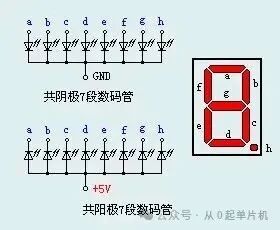
Segment Selection Lighting Logic
Common Anode: Lights up when the segment selection is connected to low level (positive → negative conduction)
Common Cathode: Lights up when the segment selection is connected to high level (positive → negative conduction)
Digit Selection Effective Signal
Common Anode: When selecting a certain digit, the common terminal is connected to high level
Common Cathode: When selecting a certain digit, the common terminal is connected to low level
3. Segment Code Derivation: Calculate the “display code” in 3 steps
Segment codes are the “binary codes” that control the display (usually converted to hexadecimal for use), with 8-bit binary corresponding to segments a→b→c→d→e→f→g→dp.
Step 1: Determine the lit segments
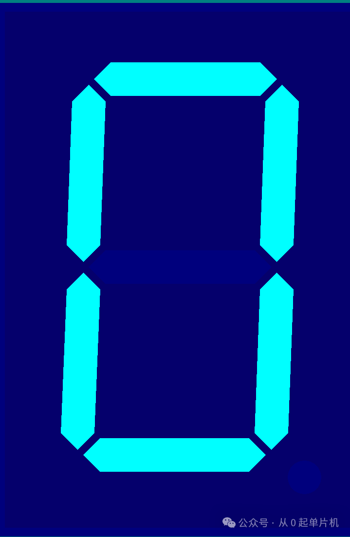
For example, the number “0” requires lighting segments a, b, c, d, e, and f (g and dp are off).
Step 2: Assign 0/1 based on type
– Common Cathode: Lit = 1, Off = 0 → Lit segments a/b/c/d/e/f correspond to 1, g/dp correspond to 0 → Binary: 11111100.
– Common Anode: Lit = 0, Off = 1 → Lit segments a/b/c/d/e/f correspond to 0, g/dp correspond to 1 → Binary: 00000011.
Step 3: Convert to hexadecimal
– Common Cathode “0”: 11111100 → 0xFC.
– Common Anode “0”: 00000011 → 0x03.
4. Conclusion
The core knowledge of 7-segment displays consists of three points:
– Static/Dynamic: Check if “time division multiplexing” is used; static consumes more lines, dynamic saves lines;
– Common Anode/Common Cathode: Check whether the common terminal is connected to positive or ground; the logic of lit segments is opposite;
– Segment Code Derivation: Achieve it in 3 steps, assign 0/1 based on the type of lit segments, convert to hexadecimal.
5. Implementing 8-Digit Dynamic Display in Proteus Simulation (Example of Common Anode)
Simulation Version 8.17 Program Version Keil5
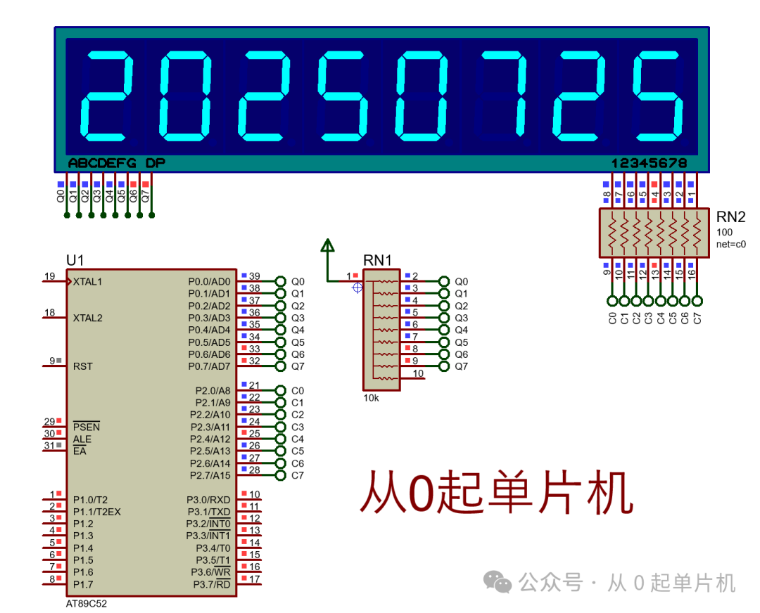
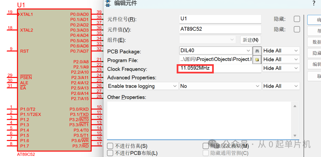
1. The simulation environment is ideal, so the minimum system peripheral circuit can be omitted; only the chip clock frequency needs to be configured.
2. Search for “7seg” in the simulation library to find the 7-segment display; CC indicates common cathode, CA indicates common anode.
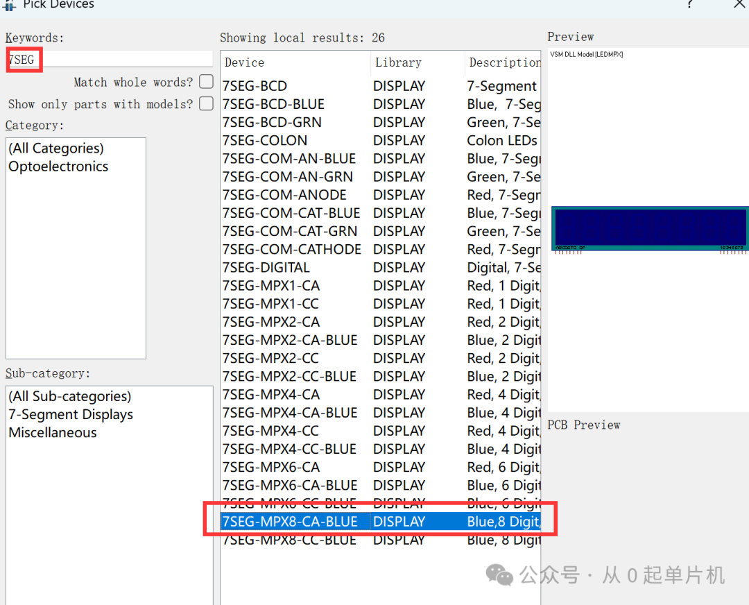
3. Connect the lines and import the program to achieve functionality.
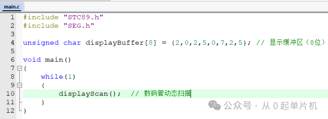
4. Some program content
1) Main function
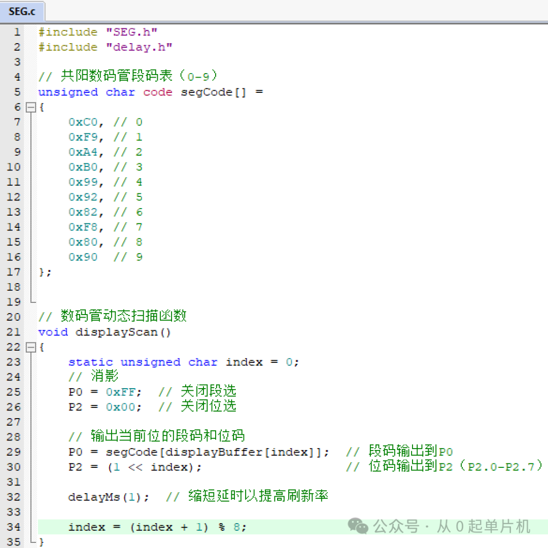
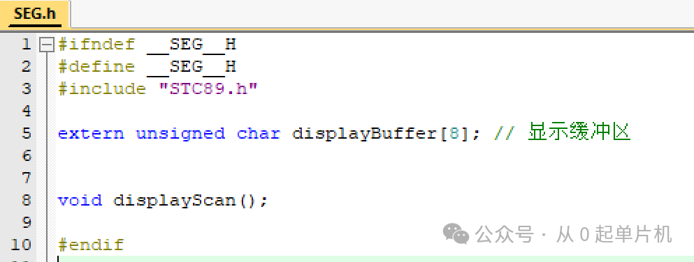
2) Common Anode Display Driver Function
Feel free to follow (this public account regularly shares microcontroller examples to help everyone grow from 0 to 1). Click the blue text “From 0 to Microcontroller” at the top or long press to identify the QR code to follow.

Reply in the public account
FZ_STC89C52_002#
After receiving, a link to this project will be automatically sent.