The creative prototype of the Fun Clock originated from an Arduino project abroad. After watching it, I was deeply impressed by its quirky charm, so I designed my own version, improving the structure and adding some extra functions.
3 x 9g servos – 10 yuan
1 whiteboard marker – 3 yuan
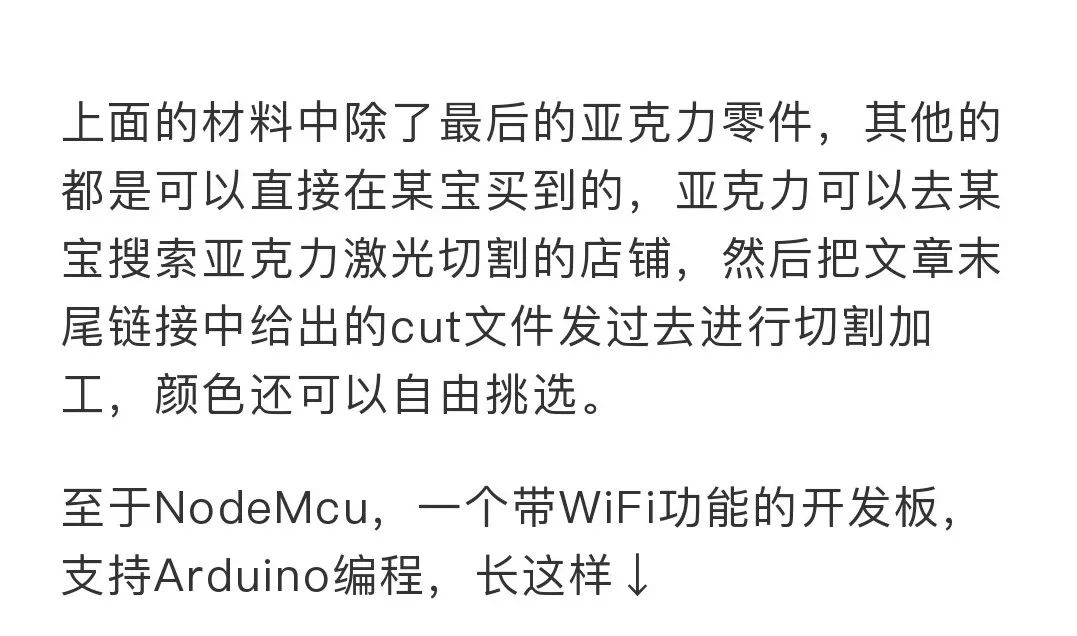
1 NodeMcu ESP8266 development board – 15 yuan
1.2MM Z-shaped steel wire for servo rods – 1 yuan
Several M3x3 flat head screws
Several M3 nuts
Several M3x12 screws
Several M3x6 T-type connecting screws
A batch of acrylic laser-cut parts
After obtaining the materials, you can assemble it according to the 3D model file. Assembly is straightforward, but some parts require attention to the order.
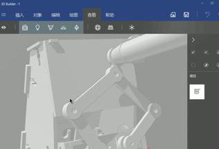
Some may not know how to view 3D model files. It’s quite simple.Windows 10 has a built-in 3D file viewer, as shown below, several software can be used to open STL format 3D files.
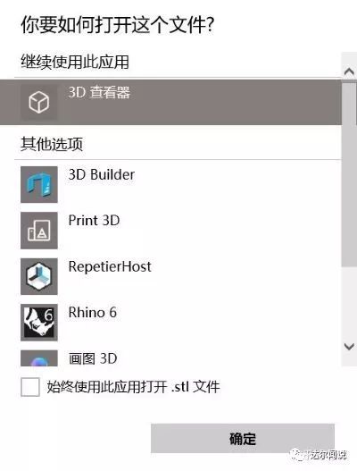
Here I recommend using 3D Builder to view; after opening, you can freely rotate and zoom to see details ↓
A video of an exploded view for reference:
Below is a bunch of acrylic parts I processed:
First assemble the servo arms. Note that some parts of the body are fixed with screws and nuts, while others may need to be glued with 502 glue.Be careful not to misalign the servo’s direction ↓
Then install the gantry and pen-lifting servo ↓
Next, install the left and right arms. The arm’s hinge is fixed using the connecting screws mentioned above. Both the large and small arms are 3mm thick, so the length of the connecting nut is 6mm, which fits perfectly;the large arm and servo are bonded with the connecting piece that comes with the servo and 502 glue ↓
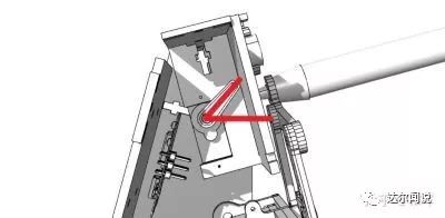
It is important to note that the screws for the arm and servo shaft, which are circled above, should not be installed yet, as there is a calibration process for the servo angles later. After calibration, the screws can be fixed.
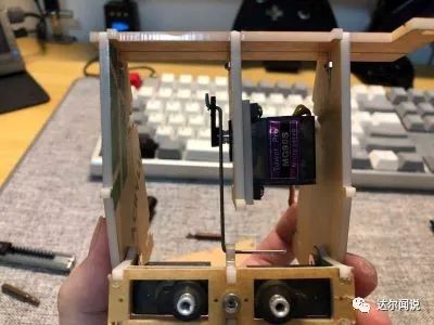
The appearance after installing the servo arm on the frame. The connecting hinge uses the connecting screws from the arm.
The pen-lifting servo and arm are connected using a servo connecting rod wire, which needs to be bent with pliers. Similar to the arm servo, the fixing screws for the arm plastic parts should not be installed yet; they will be fixed after the program calibration is done.
The final completed product. The back is made of transparent acrylic, and a light-sensitive resistor is added on the PCB, which allows it to automatically stop working when the lights are off. ↓↓↓
Hardware assembly is complete; next is the circuit connection. As shown above, I used a small PCB circuit board of my own design. The schematic and PCB files are open source, and you can download them by replying “Fun Clock” on the “Darwen Says” WeChat public account.
If you don’t want to process the PCB yourself, I will introduce the circuit connection method using NodeMcu:
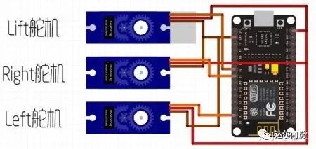
As shown above, the yellow signal wires of the left, right, and pen-lifting servos are connected to the D1, D5, and D6 pins of the NodeMcu, respectively. The black Gnd wires of the servos are connected to Gnd, which is the negative power supply, and the red Vcc wires are connected to the positive power supply input.
No other connections are needed; nice & easy~
The next step is to upload the program to the development board. If you have used Arduino, it should be no pressure. First, install the ESP8266 board package and the two required library files (both can be downloaded by replying “Fun Clock” on the “Darwen Says” WeChat public account).
Open the Arduino IDE, select the board and port, and click upload. The IDE configuration is as follows, where the port should be selected based on your actual port ↓
For those unfamiliar with Arduino, first download the IDE from the Arduino website, link is:
www.arduino.cc/en/Main/Software
Then, extract the files from my project:
Arduino\Libraries\If the Arduino IDE has not installed ESP8266\Arduino15.zip
Extract the file to this directory on your computer:
C:\Users\[Your Username]\AppData\Local
Extract the downloaded Arduino IDE, right-click the provided project file:
Arduino\DoubiBot_Firmware\DoubiBot_Firmware.ino
Select: Open with – Choose another app – Find arduino.exe in the IDE directory, and then configure it as shown in the configuration image above. Plug in the development board and click the upload arrow in the top left corner; wait for the upload to complete, and it’s done.
Here is an explanation of some contents in the code:
//#define DRAW_WEATHER//#define DRAW_TIME
These two lines are commented out, so after downloading the program, there will be no action by default. If you want to write the time, remove the // before the second line; if you want to draw the weather, remove the // before the first line.
const char* SSID = "***"; // Name of the WiFi to connect toconst char* PASSWORD = "***"; // Password of the WiFi to connect toconst char* CITY = "shanghai";
This is understandable; just change it to your WiFi name and password. If using the weather feature, change the CITY to the lowercase pinyin of your city.
// uncommet this to do calibration, code will be blocked herecontrol.Calibrate();
This line is crucial. The calibration mentioned earlier is set here. First, after modifying the code as described above and downloading, when the servo powers on, it will turn to a position and then stop because the code will be blocked here.At this point, you need to adjust the positions of the three servo arms to the following state:
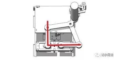
The two arms should be in an L shape.
The pen-lifting servo should be at a 45-degree angle.
Once everything is adjusted, uncomment this line:
// uncommet this to do calibration, code will be blocked here// control.Calibrate();
Upload the program again, and you will see the robot start to draw things. Mission accomplished~
The following video demonstrates the effect of sending commands to the Fun Clock via the computer’s serial assistant. Note that the bottom left corner of the whiteboard is the zero point.
For detailed code comments, you can refer to the project files I provided. Have fun!
Darwen shares the “Zhi Hui” series – I am Zhi Hui, regularly sharing cutting-edge knowledge about artificial intelligence on “Darwen Says”.
 I just follow “Darwen Says”
Zhi Hui’s personal website: www.pengzhihui.xyz
Review of Zhi Hui’s past articles:
-
Should beginners play with embedded hardware using microcontrollers or Raspberry Pi?
-
How to make a “Raspberry Pi” – DIY ARM-Linux card computer
-
Do you have interesting projects made with microcontrollers or open-source hardware?
-
Is it feasible to make a magnetic levitation device for graduation design? PID algorithm enhances stability
-
How to make a super mini voice assistant?