Click the “blue words” above to follow us!
2025.06.18
Word count: 5056
Estimated reading time: 13 minutes
Abstract
This article proposes a design for a secure and trusted circuit based on the security requirements of the boot process for embedded devices, achieving a trusted embedded system. The design method of this secure and trusted circuit is analyzed, starting with interactive verification after powering on the embedded device, followed by using a security module to measure the integrity of the data during the boot process, thus realizing a trusted embedded system. Experimental results show that the security module features security and low latency. Integrity measurement can be achieved in trusted embedded systems, ensuring the secure boot of embedded devices.
Keywords
Uboot; Secure Boot;STM32; Security Module; Trusted Embedded System
Authors: Zhao Hua1,2, Zhang Yuxin1,2, He Yingli1,2
Classification Number: TP368.1
Document Identification Code: A
0 Introduction
Currently, with the increasing performance of embedded processors, embedded technology has developed rapidly, and embedded systems are widely used in people’s daily lives. The security of embedded devices is facing more intense attacks, and the threats to embedded systems are continuously increasing. Existing embedded systems lack practical trusted measurement mechanisms and data confidentiality protection methods, making devices vulnerable to attacks. Security has become one of the main factors restricting the rapid development of embedded systems.
To address the above issues, trusted computing technology can be introduced into the embedded field. At the beginning of the embedded device’s boot process, the Bootloader is first executed, initializing hardware devices and establishing a memory mapping to bring the system’s software and hardware environment to a secure and trusted state, preparing the correct environment for the final invocation of the operating system kernel. References
Using a SHA-1 algorithm security module, without changing the original hardware structure of the embedded device, research has been conducted on integrity measurement of the boot code. First, the article uses an external communication interface for interactive verification to ensure the boot process of the embedded device, which is easily tampered with. Secondly, in 2005, cryptanalysts discovered effective attack methods against SHA-1, indicating that this algorithm may not be secure enough for continued use. Finally, the article lacks research on attack code identification and dynamic measurement of the operating system. References
Focusing on the research of trusted roots under the x86 architecture and BIOS integrity verification, it does not address security protection during the operating system’s runtime and kernel parameter protection. References
Only focusing on security protection during the operating system’s runtime and kernel parameter protection, detecting legitimate logins and attack code identification, without studying whether the operating system image has been tampered with or damaged. This article combines practical applications to improve embedded devices and designs an embedded secure boot system.
1 Design of Secure Boot Module
The secure module is a system with independent functions, built-in cryptographic computation engine, and storage area, providing encryption and data protection functions independent of the main processor. The microcontroller has EEPROM/Flash for users to store programs and working data. To prevent unauthorized users from accessing or copying the internal programs of the microcontroller, most microcontrollers come with encryption lock positioning or encrypted bytes to protect the internal programs. If the encryption lock positioning is enabled (locked) during programming, the program inside the microcontroller cannot be read directly with a regular programmer, which is called microcontroller encryption or chip encryption. However, existing microcontroller chip design vulnerabilities or software defects can be exploited by attackers, who can use specialized or homemade devices to crack or decrypt these locks. To enhance the security of the internal program code, STC has launched MCS-51 compatible chips, and ST’s STM32 series chips, all of which have a unique chip ID. Therefore, this feature can be fully utilized in the control program to enhance the protection of the control program code, and the encryption steps can be carried out as shown in the flowchart in Figure 1.
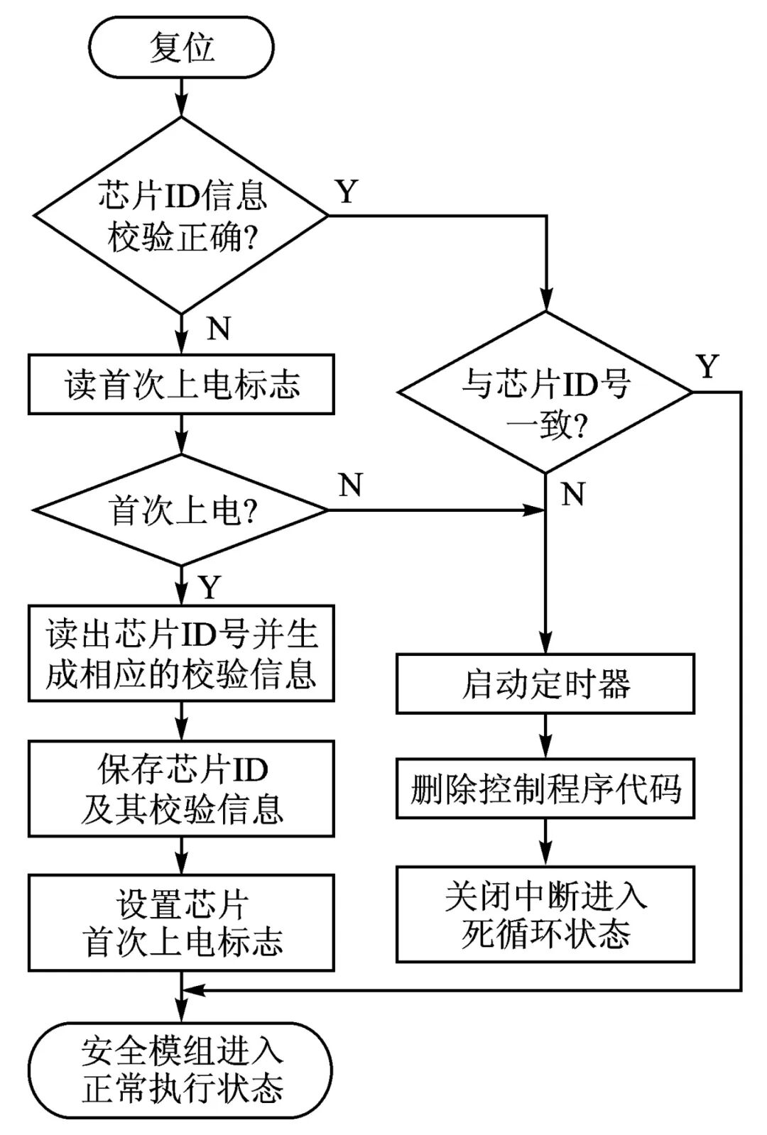
Figure 1 Unique ID Encryption Flowchart
Setting the first power-on flag is to facilitate determining whether it is the first startup after programming. On the first power-on, the chip’s ID number is read and saved. To prevent attackers from finding the chip ID information through simulation, the design does not store the original code of the ID number but instead encrypts it and disperses it into different Flash ROM storage units; the verification method should not use common, simple verification rules but should adopt some special verification methods to make it difficult for attackers to quickly determine the verification algorithm. To prevent attackers from obtaining useful code in the control program segment, once an inconsistent ID number is detected, the control program code is deleted using the IAP programming method.
2 Establishing a Trusted Chain for Embedded Systems
This article fully studies the particularities of embedded devices and draws on the trusted PC trust chain technology structure from TCG specifications to construct a trust chain model suitable for industrial control platforms. This trust chain structure optimizes and improves the trusted PC trust chain structure based on the characteristics of intelligent devices.
After powering on the embedded system, it first boots from the Bootloader. In this article, before the Bootloader, the hardware circuit is optimized, and the security module is designed as the starting point of the system’s trust chain, making the security module a hardware and software module with measurement functions. At the same time, the boot system will start from the security module, first measuring the trustworthiness of the Bootloader and Uboot. The security module will make a judgment based on the measurement results; if both are secure and trusted, it will then reset the embedded CPU.
2.1
Hardware Structure Design with Specific Interfaces
In response to the logical structure of the trust chain of embedded platforms and the diversity and scalability characteristics of current embedded mobile platforms, a hardware structure of the security module with specific interfaces has been designed, as shown in Figure 2. Like other hardware modules, the security module is equipped with a microcontroller, ROM, and RAM. A high cost-performance, low-power STM32 microprocessor is used, and an OTP chip serves as the trusted root.
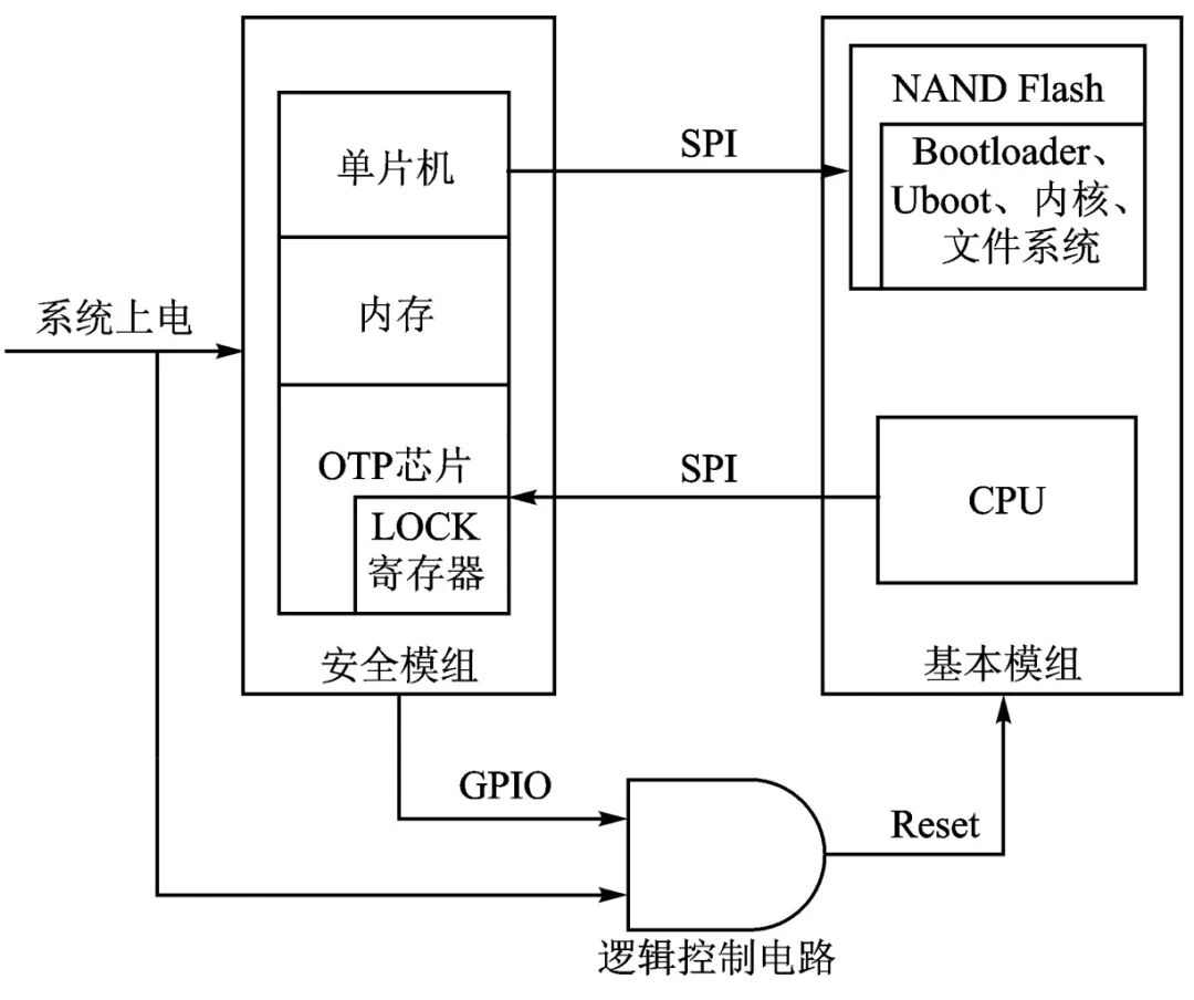
Figure 2 Hardware Structure of the Security Module
Currently, most TPMs compliant with TCG specifications use interfaces such as LPC, which are clearly not suitable for embedded mobile platforms. The startup circuit of the security module uses the SPI bus to communicate with the embedded mobile platform. SPI stands for Serial Peripheral Interface, which allows the MCU to communicate with various peripheral devices serially to exchange information. The SPI interface is used for synchronous serial data transmission between the CPU and peripheral low-speed devices. Under the shift pulse of the master device, data is transmitted bit by bit, and full-duplex communication can be achieved, with data transmission speeds reaching tens of Mbps.
Based on the functional characteristics of traditional TPMs and the actual working mode of embedded mobile platforms, the logical structure of the trusted hardware circuit security module for embedded platforms has been designed (as shown in Figure 3), including the trusted root, cryptographic engine, measurement values and event descriptions, computing engine, measurement result area, and measurement event storage.
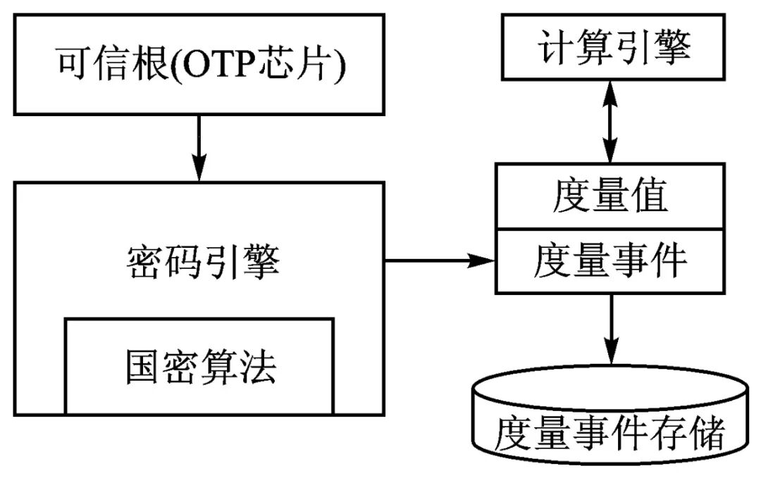
Figure 3 Logical Structure Design of the Security Module
The trusted root is used to store the measured initial software and hardware, and the trusted root is stored in an OTP (One Time Programmable) chip with security features. The OTP chip provides multiple protections and a LOCK register. Each bit of the LOCK register corresponds to an OTP chip. If the bit (BIT) corresponding to the OTP is written from 1 to 0, it means that the locked OTP can no longer be written, even if the current value of the OTP is 0xFFFFFFFF, its value cannot be rewritten.
2.2
Signature Verification Process
Signature verification is conducted through the OTP register and LOCK register, where the factory public key information is stored in the OTP. The public key is stored in a hardware-protected secure area within the OTP chip. This secure area is write-protected by the characteristics of the OTP chip, preventing the possibility of illegal tampering with the public key. The OTP chip serves as the trusted root, and the signature process is illustrated in Figure 4.
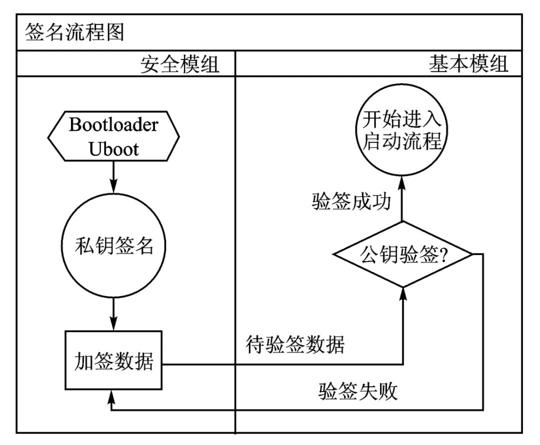
Figure 4 Signature Process Flowchart
The signature process is as follows:
① The device manufacturer generates a pair of keys (public and private keys), keeping the private key confidential. The public key is stored in the secure module’s OTP chip and can be read.
② The device manufacturer signs the Bootloader and Uboot with the private key, forming a signature, and stores the signed message and the message in the embedded device’s NAND Flash.
③ During device startup, the security module first powers on and resets, reads the data from the embedded device’s NAND Flash, and verifies the signature using the public key in the OTP chip. If the verified content matches the message itself, it proves that the signature is successful, and the embedded device begins to reset.
In this process, even if a third party intercepts the public key, there is no risk because only the device manufacturer’s private key can sign the message. Even if the message content is known, it cannot forge the signature, thus preventing content tampering. The above signature has two effects: first, it can confirm that the information content is indeed signed and sent by the device manufacturer, as no one can impersonate the device manufacturer’s signature; second, the digital signature can ensure the integrity of the information.
2.3
Integrity Protection of Measurement Evidence Information
The measurement information of the embedded platform is stored in the secure module’s OTP chip via the SPI interface. In trusted embedded devices, measurement evidence information is stored in the platform configuration registers (PCR) inside the TPM chip, while the root key is stored in the non-volatile memory of the TPM, protected by TPM hardware, ensuring high security. The security module designed in this article does not require a TPM chip; to ensure the security and trustworthiness of its measurement evidence information, this article adopts a digital signature method to achieve integrity protection of measurement evidence information. In the security module system, the root key (SRK) is stored in the OTP chip. The storage root key is protected by the hardware of the OTP chip, ensuring the absolute security of the SRK. Each time the reference value is extracted, it is signed for verification to ensure the integrity of the reference information, as shown in Figure 5.
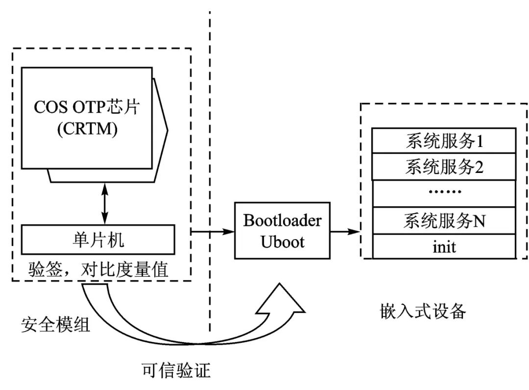
Figure 5 Trust Chain of Embedded Platform
3 Implementation of Secure Boot for Trusted Embedded Systems
A trusted embedded system is constructed by adding hardware with security protection functions to embedded devices, creating a trusted computing environment through a combination of hardware and software. The trusted embedded system in this article enhances the security of embedded devices by incorporating a security module. The security module connects to the embedded device via the SPI interface, providing security functions. The security of the boot process of embedded devices is the foundation of runtime security, so the trusted embedded system must ensure the security of the system’s boot.
In embedded devices, the system’s bootloader, operating system kernel, and file system are typically stored in external memory outside the microprocessor. After powering on, the system boots from external memory, first running the bootloader, which reads and copies the operating system kernel into memory, and finally starts the kernel to complete the system boot.
In trusted embedded systems, to achieve secure boot of embedded devices, integrity measurement of the program code during the boot process is primarily conducted. Only program code that has passed integrity verification is allowed to run in the processor, thus avoiding threats to the system from tampered boot processes. However, since the trusted embedded system in this article does not alter the original hardware structure of the embedded device, the security module cannot directly read the program code located in external memory for integrity measurement via the SPI interface. Therefore, it must utilize the processor to read from external memory and then complete communication with the security module through the external communication interface. Because the original hardware structure of the embedded device has not changed, the system boots from its external memory. During the secure boot process, the STM32 security module must first measure the integrity of the bootloader. If the boot process has already been tampered with, there may be a situation where the SHA-1 module is not called for integrity verification and runs directly, leading to an insecure boot process.
This article conducts interactive verification of the embedded device and the security module after powering on the entire system, ensuring that the boot process of the embedded device proceeds as planned, and that the bootloader and other runtime calls utilize the STM32 module for integrity verification. The interactive verification process guarantees that the embedded device is connected to the security module upon power-up, and after completing the interactive verification, integrity measurement is performed. The interactive verification flowchart after powering on the system is shown in Figure 6.
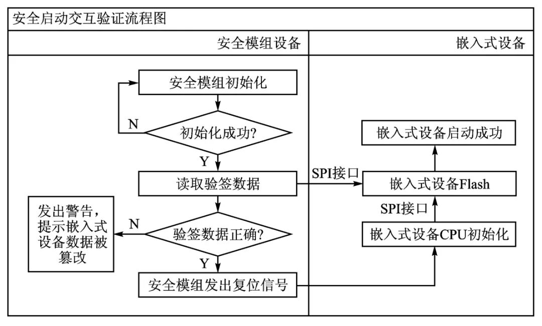
Figure 6 Interactive Verification Flowchart
The author applied the designed security module to the NXP1021 hardware platform and verified the proposed secure boot process. In the NXP1021 platform, the bootloader, operating system kernel, etc., are stored in NAND Flash. After powering on, the NXP1021 reads and copies Uboot and Kernel from NAND Flash, then waits to receive interactive verification commands. The NXP1021 receives the interactive verification command and checks its correctness. After passing the interactive verification, it calls the encryption module in the security module to perform integrity measurement on the Uboot and Kernel data. If the integrity verification passes, as shown in Figure 7.
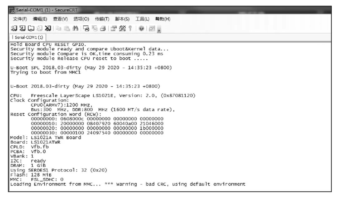
Figure 7 Integrity Verification Passed
If the integrity verification fails, the system startup is prohibited. The NXP1021 is prohibited from running, and the system startup fails, as shown in Figure 8.
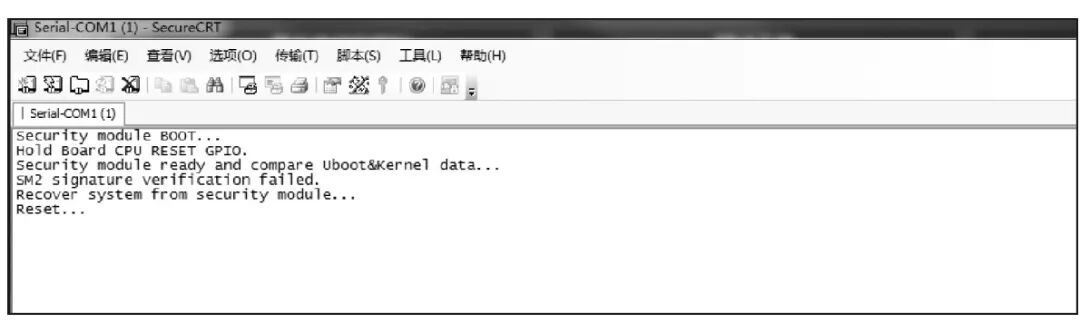
Figure 8 Integrity Verification Failed
4 Conclusion
The secure boot method utilizing integrity verification can maintain the original hardware structure of existing embedded devices, providing universal adaptability. To enhance the security of existing embedded devices, a trusted embedded system is constructed by adding a security module. Based on this structure, the author proposed a secure boot design for embedded devices and modified it on the hardware platform, verifying that interactive verification is conducted after powering on the embedded device, ensuring that the embedded device operates as planned while connected to the security module, and utilizing the STM32 module for integrity measurement of the program code during the boot process, ensuring that the system’s boot process has not been tampered with.
References

[1] Luo Jun, Jiang Jingqi, Min Zhisheng, et al. Secure Boot Method for Trusted Embedded Systems Based on SHA-1 Module[J]. Shandong University Journal (Natural Science Edition), 2012(9):1-2.
[2]] Shi Jiangyi, Hao Yue, Zhu Zhiwei, et al. Synchronization Design Method of IP Cores in SoC[J]. Electronic Devices, 2007,30(3):984-987.
[3]] Feng Dengguo. Trusted Computing Theory and Practice[M]. Beijing: Tsinghua University Press, 2013.
[4]] Gu Liang, Guo Yao, Wang Hua, et al. Runtime Software Trusted Evidence Collection Mechanism Based on TPM[J]. Journal of Software, 2010,21(2):373-387.
[5]] Zhao Bo, Fei Yongkang, Xiang, et al. Research and Implementation of Secure Boot Mechanism for Embedded Systems[J]. Computer Engineering and Applications, 2014,50(10):72-77.
[6]] National Cryptography Administration. SM3 Cryptographic Hash Algorithm[EB/OL]. [2021-05]. http://www.oscca.gov.cn/News/201012/News-1199.html.
[7]] Wei Hang, Cui Huili, Lü Xiaoqing. Differential Algebraic Analysis of SMS4 Block Cipher Algorithm[J]. Journal of Chengdu University (Natural Science Edition), 2012,31(2):158-160.
(Author Affiliation: 1. NARI Group Corporation (State Grid Electric Power Research Institute Co., Ltd.), Nanjing 211106; 2. Nanjing NARI Information Communication Technology Co., Ltd.)
(This article is authorized for publication by the “Microcontroller and Embedded System Applications” magazine, originally published in the 11th issue of 2021)
END
[Click the above👆🏻search term to view more other content in the account]

Follow us to learn more exciting content
 Share, like, and check it out?