Tan Zengqiao, Lu Zhengliang, Zhang Xiang
(Nanjing University of Science and Technology, School of Mechanical Engineering, Jiangsu Nanjing 210094)
Abstract: In order to meet the requirements of CubeSats for high performance, low power consumption, and rich peripheral interfaces for attitude control computers, this paper designs a CubeSat attitude control computer based on the low-cost, low-power STM32 chip. First, a comprehensive analysis of the CubeSat mission is conducted, and a general design scheme for the attitude control computer is proposed; then, based on the requirements, the hardware system of the attitude control computer is designed, focusing on the selection of the main control chip, the design of the basic peripheral circuits of the main chip, and the interface circuit design between the main chip and various components of the attitude control; finally, the physical prototype of the attitude control computer is experimentally verified. The results show that the modular CubeSat attitude control computer designed based on the STM32 chip has advantages such as high integration, low cost, low power consumption, high performance, lightweight, and strong engineering applicability.
Keywords: CubeSat; Attitude Control Computer; STM32; Hardware System Design; Hardware Testing; Interface Circuits; Simulation Verification; Embedded Design
Classification Number: TN927⁃34; TP311 Document Identification Code:A
Article Number:1004⁃373X(2022)02⁃0057⁃05
0 Introduction
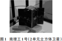
The CubeSat[1](CubeSat) originated from a scientific research project at California Institute of Technology and Stanford University in 1999, where scholars at Stanford proposed the concept of a CubeSat and defined the mass of a one-unit CubeSat as1kg, with structural dimensions of100mm×100mm×100mm, making CubeSats a universal standard for nanosatellites, as shown in Figure1[2]. With the miniaturization and integration trends in mechanical and electronic industries, as well as the diversification of space missions, CubeSats have gradually become a research hotspot in the aerospace field both domestically and internationally due to their low development cost, short development cycle, high functional density, and flexible deployment[3].
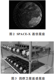
 As space technology matures, CubeSats can achieve complex technical operations such as wide-range orbital maneuvers, formation control, rendezvous proximity operations, and space capture[4], making them widely used in communication (as shown in Figure2), remote sensing (as shown in Figure3), environmental monitoring, scientific experiments, and space offense and defense tasks[5⁃7]. The realization of these technologies imposes increasingly high requirements on satellite attitude control. The attitude control computer serves as the control center of the Attitude Determination and Control System (ADCS), responsible for tasks such as sensor data acquisition, data processing, attitude determination, and attitude control. Currently, attitude control computers used in large satellites have developed relatively maturely, but in the miniaturization process, conflicts arise between computational capability, control capability, power consumption, and cost. Therefore, how to design a low-cost, low-power, high-performance attitude control computer has become an urgent problem to solve.
 Currently, domestic attitude control computers have been designed using chips such as386,DSP,FPGA[8⁃10]: the 386 CPU has a low computation speed and is not ideal in terms of structure and power consumption; DSPs, while having fast computation speeds, face issues such as loose coupling and long hardware debugging cycles; FPGAs, although flexible in design, have weak control capabilities due to the lack of an instruction system. In contrast, STM32[11⁃12] chips are compact, highly integrated, low-cost, low-voltage, low-power, have strong data processing and computational capabilities, and possess strong control capabilities. Therefore, this paper designs a low-cost, low-power, high-performance attitude control computer with rich peripheral interfaces suitable for CubeSats based on the STM32 chip. The article first analyzes the requirements for the attitude control computer based on CubeSat missions, and then completes the overall design of the attitude control computer; next, the hardware design of each part of the attitude control computer is completed; finally, the hardware implementation and testing of the attitude control computer are completed.
1 Overall Design Scheme
The main function of the attitude control computer is to determine the current attitude of the satellite through the measurement information from multiple attitude sensors onboard, and then control the actuators based on the current attitude information through attitude control algorithms to achieve satellite attitude control. Currently, for attitude control systems of small satellites such as CubeSats, the mainstream configuration of attitude sensors includes magnetometers, gyroscopes, sun sensors, andGPS. If high precision is required for attitude determination, star sensors can be added to enhance attitude determination accuracy; commonly used actuators in attitude control include magnetic torquers and momentum wheels. Based on these configurations of the attitude control system, the overall design scheme of the attitude control computer proposed in this paper is shown in Figure4.
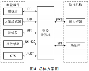 In Figure4: The attitude control computer is mainly responsible for determining and controlling the satellite’s attitude; the magnetometer is used to measure the Earth’s magnetic field at the satellite’s location, transmitting data to the attitude control computer via the I2C communication protocol, designed with a cold backup method; the sun sensor measures the angle between the satellite surface and sunlight, generating corresponding quadrant currents, which are converted into I2C signals input to the attitude control computer, requiring a total of 3 paths of I2C; the gyroscope measures the satellite’s three-axis angular velocity, transmitting data to the attitude control computer via SPI; the star sensor determines the satellite’s current attitude through star map comparison, transmitting data to the attitude control computer via RS 422; the GPS module provides the attitude control computer with UTC time, position, and velocity information, transmitting data via UART; the momentum wheel outputs torque to counteract disturbance torques, thus achieving satellite attitude control, with the attitude control computer controlling the momentum wheel’s drive chip via 1 path of SPI; the magnetic torquer is mainly used for angular velocity damping after satellite separation and for unloading the momentum wheel during three-axis stabilization, with the attitude control computer’s I/O port outputting PWM waves to control the magnetic torquer’s drive chip, thus controlling the output torque of the magnetic torquer. Since the satellite attitude control system involves multiple attitude sensors, a large amount of rapid attitude information reading is required, which demands high real-time performance for data transmission and processing; additionally, it involves complex calculations for attitude determination and control algorithms, as well as actuator control. Therefore, the attitude control computer must have high data computation and control capabilities, with peripheral interfaces requiring fast data transmission speeds. Comprehensive analysis of satellite mission requirements leads to the following performance requirements for the attitude control computer: computation speed ≥150MHz, SRAM=2MB, FLASH=1MB, mass ≤0.5kg, power consumption ≤2W (for long-term three-axis stabilization); interface requirements mainly include: 12 paths of 12-bit A/D, 2 paths of 12-bit D/A, 4 paths of I2C, 2 paths of SPI, 1 path of RS 422, and 4 paths of RS 232.
2 Hardware Design of the Attitude Control Computer
2.1 Core Microcontroller Selection
The STM32 series microcontrollers are 32-bit microcontrollers based on the ARM Cortex-M core, launched by ST (STMicroelectronics), supporting a wide range of 32-bit applications. Literature[13] describes the design of a high-precision solar tracking system based on a fiber array using the STM32F1 series chip; literature[14] describes the design of an X-type quadrotor UAV based on the STM32F4 series chip. The STM32F4 series chip is a high-performance microcontroller based on the ultra-low power ARM Cortex-M4 core, with the STM32F407 operating at a frequency of up to 168 MHz, featuring 140 fast I/O ports and up to 15 standard communication interfaces, 2 CAN interfaces, 4 USART, 2 UART, 3 I2C interfaces, 3 paths of SPI, and 1 SDIO interface, capable of operating at low voltages (1.8~3.6 V). Based on these resources and characteristics of the STM32F407, it meets the requirements of low power consumption, high performance, and rich interfaces for the attitude control computer. Additionally, the normal operating temperature range of this chip is -40~+85 ℃, suitable for satellite working conditions. Therefore, this paper selects the STM32F407 as the main chip, along with peripheral circuits to implement the design of the attitude control computer.
2.2 Basic Peripheral Circuit Design
A CC5V⁃TIA⁃32.768 chip is used to provide a frequency of 32.768 kHz as the external clock for the system, configurable through phase-locked loop and pre-dividers into two AHB buses, high-speed APB (APB2, highest frequency up to 84 MHz) and low-speed APB (APB1, highest frequency up to 42MHz).
In Figure4: The attitude control computer is mainly responsible for determining and controlling the satellite’s attitude; the magnetometer is used to measure the Earth’s magnetic field at the satellite’s location, transmitting data to the attitude control computer via the I2C communication protocol, designed with a cold backup method; the sun sensor measures the angle between the satellite surface and sunlight, generating corresponding quadrant currents, which are converted into I2C signals input to the attitude control computer, requiring a total of 3 paths of I2C; the gyroscope measures the satellite’s three-axis angular velocity, transmitting data to the attitude control computer via SPI; the star sensor determines the satellite’s current attitude through star map comparison, transmitting data to the attitude control computer via RS 422; the GPS module provides the attitude control computer with UTC time, position, and velocity information, transmitting data via UART; the momentum wheel outputs torque to counteract disturbance torques, thus achieving satellite attitude control, with the attitude control computer controlling the momentum wheel’s drive chip via 1 path of SPI; the magnetic torquer is mainly used for angular velocity damping after satellite separation and for unloading the momentum wheel during three-axis stabilization, with the attitude control computer’s I/O port outputting PWM waves to control the magnetic torquer’s drive chip, thus controlling the output torque of the magnetic torquer. Since the satellite attitude control system involves multiple attitude sensors, a large amount of rapid attitude information reading is required, which demands high real-time performance for data transmission and processing; additionally, it involves complex calculations for attitude determination and control algorithms, as well as actuator control. Therefore, the attitude control computer must have high data computation and control capabilities, with peripheral interfaces requiring fast data transmission speeds. Comprehensive analysis of satellite mission requirements leads to the following performance requirements for the attitude control computer: computation speed ≥150MHz, SRAM=2MB, FLASH=1MB, mass ≤0.5kg, power consumption ≤2W (for long-term three-axis stabilization); interface requirements mainly include: 12 paths of 12-bit A/D, 2 paths of 12-bit D/A, 4 paths of I2C, 2 paths of SPI, 1 path of RS 422, and 4 paths of RS 232.
2 Hardware Design of the Attitude Control Computer
2.1 Core Microcontroller Selection
The STM32 series microcontrollers are 32-bit microcontrollers based on the ARM Cortex-M core, launched by ST (STMicroelectronics), supporting a wide range of 32-bit applications. Literature[13] describes the design of a high-precision solar tracking system based on a fiber array using the STM32F1 series chip; literature[14] describes the design of an X-type quadrotor UAV based on the STM32F4 series chip. The STM32F4 series chip is a high-performance microcontroller based on the ultra-low power ARM Cortex-M4 core, with the STM32F407 operating at a frequency of up to 168 MHz, featuring 140 fast I/O ports and up to 15 standard communication interfaces, 2 CAN interfaces, 4 USART, 2 UART, 3 I2C interfaces, 3 paths of SPI, and 1 SDIO interface, capable of operating at low voltages (1.8~3.6 V). Based on these resources and characteristics of the STM32F407, it meets the requirements of low power consumption, high performance, and rich interfaces for the attitude control computer. Additionally, the normal operating temperature range of this chip is -40~+85 ℃, suitable for satellite working conditions. Therefore, this paper selects the STM32F407 as the main chip, along with peripheral circuits to implement the design of the attitude control computer.
2.2 Basic Peripheral Circuit Design
A CC5V⁃TIA⁃32.768 chip is used to provide a frequency of 32.768 kHz as the external clock for the system, configurable through phase-locked loop and pre-dividers into two AHB buses, high-speed APB (APB2, highest frequency up to 84 MHz) and low-speed APB (APB1, highest frequency up to 42MHz).
2.2.2 Power Supply Circuit
To simplify the power supply circuit, when selecting components such as sensors and actuators, devices with power supply voltages in the same range are chosen as much as possible, so the entire attitude control system only requires two power supply standards:5V and 3.3V. The external bus power supply voltage is 7.4 V, thus requiring a voltage conversion chip. This paper uses both ADP3303 and LMZ12001 chips to achieve 5V and 3.3V supply. To ensure stable input and output, capacitors are connected in series between the input/output pins and ground.
The TPS382X series monitors provide circuit initialization and timing monitoring mainly for DSPs and processor-based systems. This series of devices has an internal voltage divider setting a fixed detection threshold voltage; when the power supply voltage exceeds the threshold voltage, a reset signal is generated. When the power supply voltage falls below the threshold voltage, it remains effective. This paper selects the TPS3823⁃3.3 chip from this series, which also includes a manual reset input pin that is activated when at a low level.
 as shown in Figure5.
2.3 Interface Design of Attitude Control Components
2.3.1 Magnetic Torquer Drive Circuit
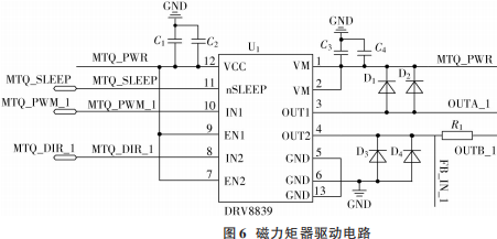
Magnetic torque is generated by the Ampere force produced by an energized coil in a magnetic field, and the magnitude of the magnetic torque can be adjusted by controlling the current in the coil. The CubeSat uses a drive chip to output current to drive the magnetic torquer,
The drive chip outputs PWM waves controlled by the main chip STM32F407’s I/O ports, and the output current can be controlled by adjusting the duty cycle of the PWM wave[15]. The driving current required for the magnetic torquer is below 1A, and the output voltage range of the main chip’s I/O ports is 0~3.3V. Therefore, this paper selects the DRV8839 chip as the drive chip for the magnetic torquer, which can provide output current up to 1.8 A, has strong driving capability, and meets the driving requirements for the magnetic torquer; the working voltage range is 1.8~7V, and it can be directly controlled by the main chip’s I/O ports. The design of the magnetic torquer driving circuit is shown in Figure6.
2.3.2 Momentum Wheel Drive Circuit
The momentum wheel selected in this paper is the 2610012B model from Follhabe Company, which operates at 12V with a maximum speed of 6400V/min, maximum torque of 3.1mN·m, rated torque of 2.85mN·m, and speed constant of 543min-1/V. The speed is controlled by the output voltage of the drive chip, which receives control instructions from the attitude control computer via SPI and converts them into voltage output to drive the momentum wheel.AD5664 is a low-power, 16-bit DAC, operating voltage is between 2.7~5.5V, and is compatible with standard SPI interfaces, meeting the above requirements.
2.3.3 Sun Sensor and Magnetometer Interface Circuit
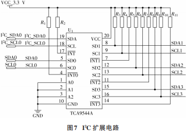
Both the sun sensor and the magnetometer communicate with the attitude control computer via I2C. This paper considers installing sun sensors on three faces of the CubeSat, with one on each face, each sun sensor generating quadrant currents, which are collected and converted into digital signals by two current acquisition chipsINA3221Q1, and exchanged with the attitude control computer via the I2C interface; the signals generated by the magnetometer are converted into data after amplification and by the A/D conversion chipADS1115, and exchanged with the attitude control computer via I2C. The main chip STM32F407 has 3 internal I2C channels, which do not meet the system requirements, and the integrated I2C is not stable enough, so this paper designs an expansion chip to extend the internal I2C. The TCA9544A is a four-channel bidirectional switching I2C multiplexer with a maximum frequency of 400kHz, and this paper uses it to extend 1 path of I2C into 4 paths for the use of 3 sun sensors and a magnetometer. The expansion circuit is shown in Figure7.
as shown in Figure5.
2.3 Interface Design of Attitude Control Components
2.3.1 Magnetic Torquer Drive Circuit
Magnetic torque is generated by the Ampere force produced by an energized coil in a magnetic field, and the magnitude of the magnetic torque can be adjusted by controlling the current in the coil. The CubeSat uses a drive chip to output current to drive the magnetic torquer,
The drive chip outputs PWM waves controlled by the main chip STM32F407’s I/O ports, and the output current can be controlled by adjusting the duty cycle of the PWM wave[15]. The driving current required for the magnetic torquer is below 1A, and the output voltage range of the main chip’s I/O ports is 0~3.3V. Therefore, this paper selects the DRV8839 chip as the drive chip for the magnetic torquer, which can provide output current up to 1.8 A, has strong driving capability, and meets the driving requirements for the magnetic torquer; the working voltage range is 1.8~7V, and it can be directly controlled by the main chip’s I/O ports. The design of the magnetic torquer driving circuit is shown in Figure6.
2.3.2 Momentum Wheel Drive Circuit
The momentum wheel selected in this paper is the 2610012B model from Follhabe Company, which operates at 12V with a maximum speed of 6400V/min, maximum torque of 3.1mN·m, rated torque of 2.85mN·m, and speed constant of 543min-1/V. The speed is controlled by the output voltage of the drive chip, which receives control instructions from the attitude control computer via SPI and converts them into voltage output to drive the momentum wheel.AD5664 is a low-power, 16-bit DAC, operating voltage is between 2.7~5.5V, and is compatible with standard SPI interfaces, meeting the above requirements.
2.3.3 Sun Sensor and Magnetometer Interface Circuit
Both the sun sensor and the magnetometer communicate with the attitude control computer via I2C. This paper considers installing sun sensors on three faces of the CubeSat, with one on each face, each sun sensor generating quadrant currents, which are collected and converted into digital signals by two current acquisition chipsINA3221Q1, and exchanged with the attitude control computer via the I2C interface; the signals generated by the magnetometer are converted into data after amplification and by the A/D conversion chipADS1115, and exchanged with the attitude control computer via I2C. The main chip STM32F407 has 3 internal I2C channels, which do not meet the system requirements, and the integrated I2C is not stable enough, so this paper designs an expansion chip to extend the internal I2C. The TCA9544A is a four-channel bidirectional switching I2C multiplexer with a maximum frequency of 400kHz, and this paper uses it to extend 1 path of I2C into 4 paths for the use of 3 sun sensors and a magnetometer. The expansion circuit is shown in Figure7.
2.3.4 Gyroscope Interface Circuit
The gyroscope selected in this paper is the ADIS16465 from ANALOG DEVICES, which is a precision micro-electromechanical system (MEMS) inertial measurement unit (IMU), with a measurement range of ±250 (°)/s, motion bias stability of 12 (°)/hr (1σ), and angle random walk of 0.56 hr (1σ). It integrates a signal processing module and SPI communication interface, eliminating the need for external conversion chips for level conversion, allowing direct communication with the attitude control computer’s main chip via SPI.
2.3.5 Star Sensor Interface Circuit
The star sensor selected in this paper is the NST-4 from Tianyin Space (TY-SPACE), which is compact, lightweight (<200g), low power consumption (<0.6W), high precision (5″, 3σ), and has high dynamic performance (2(°)/s) and strong anti-glare performance. The communication interface is RS422. The main chip STM32F407 does not integrate an RS422 communication interface, so a conversion chip is needed to convert 1 serial port to RS422 levels for communication with the star sensor. The MAX3488 is a low-power transceiver for RS485 and RS422 communication, operating voltage of 3.3V. This chip features a slew-rate limited driver that minimizes electromagnetic interference and reduces reflections caused by incorrect cable ends, allowing error-free data transmission rates of up to 250 Kb/s, meeting the requirements of this paper. Therefore, this paper selects the MAX3488 to complete the level conversion for RS422.
2.3.6 GPS Interface Circuit
The GPS module is designed based on STM32F205, and communicates with the attitude control computer via UART; both STM32F205 and the main chip STM32F407 have UART communication interfaces. This paper uses USART1(PA9,PA10) from STM32F205 and UART4(PC10,PC11) from STM32F407 for communication.
3 Hardware Implementation and Testing
3.1 Hardware Implementation
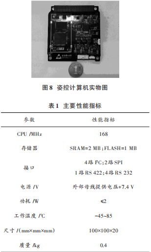
Based on the overall design scheme and hardware circuit design mentioned above, the final physical prototype of the attitude control computer is shown in Figure8, connected to other components onboard via PC104 and connected to the hardware interfaces of various components through Molex connectors. The performance indicators of the attitude control computer are shown in Table1, meeting the requirements of the attitude control system for the attitude control computer.
3.2 Testing Results and Analysis
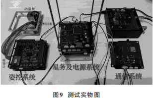
The attitude control computer was connected to the overall satellite for system testing, as shown in Figure9.
In the figure, the left part shows the attitude control system, including the magnetic rod board, attitude control computer, and magnetometer board, with the momentum wheel connected via an adapter board; the middle part shows the power supply system and satellite computer, responsible for power supply and task management onboard; the right part shows the communication module, responsible for the transmission and reception of remote control telemetry information. The testing results are shown in Figure10.
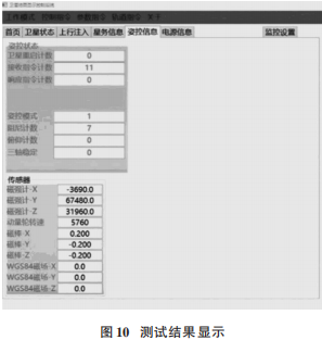
The testing results indicate that the readings from all sensors in the attitude control system are normal, the actuators are functioning properly, and the attitude control computer is in good working condition, meeting the design requirements.
4 Conclusion
This paper designs a CubeSat attitude control computer based on the STM32F407 chip, mainly including some basic peripheral circuits of the main chip and the interface designs between the attitude control computer and the attitude control components. The design scheme considers various commonly used attitude sensors and actuators on CubeSats, enabling it to adapt to the requirements of multiple attitude control configuration modes; the main chip’s powerful computing and control capabilities can meet the real-time requirements of complex attitude control algorithms and the multitasking capabilities of the system. Practical testing applications indicate that the attitude control computer designed in this scheme possesses strong practicality, reliability, and stability, with low cost and low power consumption, making it a standard component for CubeSat attitude control systems.
[1] Liao Wenhe. Development and Application of CubeSat Technology [J]. Journal of Nanjing University of Aeronautics and Astronautics, 2015, 47(6):792⁃797.
[2] SHKOLNIK, EVGENYA L. On the verge of an astronomyCubeSat revolution [J]. Nature astronomy, 2018, 2(5):374 ⁃378.
[3] Shi Peng, Su Xiaohua, Wang Qin, et al. The Development Trends and Insights of International Space Science Based on CubeSat Platforms [J]. Science and Technology Review, 2019, 37(21):63⁃72.
[4] Jia Ping. Analysis of the Development and Application Modes of Foreign CubeSats [J]. China Aerospace, 2016(2):19⁃22.
[5] YU H X, WANG M Q, XU L Y, et al. Application of Bayesian Super-Resolution Imaging Algorithm to Micro-Nanosatellite Images [J]. Journal of Applied Remote Sensing, 2019, 13(3):1.
[6] SAEED N, ELZANATY A, ALMORAD H, et al. CubeSat communications: recent advances and future challenges [J]. IEEE Communications Surveys & Tutorials, 2020(99):1.
[7] CHAHAT N, HODGES R E, SAUDER J, et al. The Deep Space Network Telecommunication CubeSat Antenna: Using the Deployable Ka-Band Mesh Reflector Antenna [J]. IEEE Antennas & Propagation Magazine, 2017, 59(2):31⁃38.
[8] Li Xingwei, Bai Bo, Zhou Jun. Research on Reconfigurable Onboard Processing System Based on FPGA [J]. Computer Measurement and Control, 2018, 26(8):172⁃176.
[9] Zhang Mingdong. Design of a High-Reliability Onboard Floating Point Computing Platform Based on DSP [J]. Modern Industrial Economy and Informationization, 2019, 9(4):32⁃33.
[10] Kang Guohua, Xia Qing, Cheng Jing. Design and Implementation of Micro-Satellite Attitude and Orbit Control Computer Based on SoPC [J]. Journal of Nanjing University of Aeronautics and Astronautics, 2013, 45(6):763⁃768.
[11] Song Kainan, Huang Qiaoliang. Design of 3U CubeSat Satellite Management and Attitude Controller Based on STM32 [J]. Marine Electronic Engineering, 2020, 40(3):48⁃53.
[12] Li Shiguang, Wang Wenwen, Shen Mengqian, et al. Design of Attitude Measurement System Based on STM32 [J]. Modern Electronic Technology, 2016, 39(9):12⁃14.
[13] Duan Huan, Huang Huilan, Li Gang. High-Precision Solar Tracking System Based on Fiber Array and STM32 [J]. Control Engineering, 2017, 24(12):2424⁃2429.
[14] Pan Chunrong, Xu Hua. Design of an X-Type Quadrotor UAV Based on STM32 [J]. Journal of Engineering Design, 2017, 24(2):196⁃202.
[15] Jiang Di, Zhang Ke. Design of CubeSat OBC Board Based on MSP430 [J]. Modern Electronic Technology, 2014, 37(8):58⁃60.
Author Information:
Tan Zengqiao (1996—), male, master’s student, research direction in testing measurement technology and instruments.
Lu Zhengliang (1990—), male, lecturer, research direction in micro-nanosatellite attitude and orbit control, semi-physical simulation technology, etc.
Zhang Xiang (1973—), male, associate researcher, research direction in micro-nanosatellite overall design technology, stealth technology, etc.
-End-
Click the link below to view historical articles
Good papers are “revised”!
CNKI’s annual price increase suspected of monopoly, how should academia and business balance?
The 2019 Issue 12 Directory of Modern Electronic Technology
Which universities published the most SCI papers and authorized patents in 2017?
Modern Electronic Technology Selected for Overview of Chinese Core Journals
Academician of the Chinese Academy of Sciences: The dominance of SCI in papers stifles scientific creativity
How to write a “Nature” article in one night, listen to what the academicians say!