1 Introduction
The Hardware Abstraction Layer (HAL) is an interface layer located between the operating system kernel and the hardware circuitry, aimed at abstracting the hardware. It hides the hardware interface details specific to a platform, providing a virtual hardware platform for the operating system, making it hardware-independent and portable across various platforms. The HAL is a programming layer that allows the operating system to interact with hardware devices at a logical level rather than a hardware level. The HAL is closely related to hardware; it is independent of the operating system; the functionality defined by the HAL interface should encompass all functions required by the hardware or system-supported hardware; the definition of the HAL interface should be simple and clear; defining too many interfaces will increase the complexity of software emulation; interfaces designed with testability in mind facilitate the testing and integration of both hardware and software systems.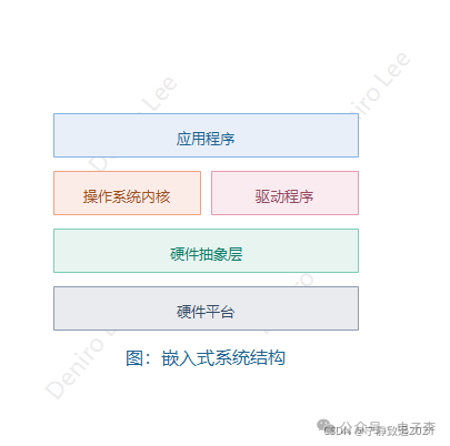
1.1 Hierarchical Design Concept
The hierarchical design is reflected in the vertical structure of embedded operating systems. To adapt to various hardware platforms, a level is separated from the operating system that can directly communicate with the hardware, providing abstract support for the upper layer, while the lower layer offers services to the upper layer in the form of APIs. This way, the upper layer does not need to understand the specific details of the devices when performing hardware operations, significantly reducing the complexity of system understanding and development. Therefore, the hierarchical approach has the following advantages: cost savings, ease of understanding, ease of expansion, and ease of debugging.
1.2 Modular Design Concept
The greatest feature of modularity is the separation of interfaces and implementations, hiding specific functional blocks behind abstract interfaces to ensure that each module can change without affecting other modules. In this way, the dependencies between modules are limited solely to interfaces. The modular approach differs from the hierarchical approach in that software modules are independent of each other, rather than being interdependent across layers.
1.3 Object-Oriented Design Concept
For the current purpose, an object is a structured way of using modules. The object-oriented design method encapsulates data and operations on that data within the object module entity, preventing external access and manipulation of the object’s internals, which can only be accessed indirectly through messages. Therefore, the object-oriented design method makes it easier for software developers to understand and also enhances the software’s extensibility, maintainability, and reusability.
The following describes the principles behind these functional implementations.
First, to better isolate the hardware-related and hardware-independent parts of the program code in embedded systems, the HAL provides an interface that masks hardware differences for upper-layer software. The HAL can be further refined into several sub-layers, adopting a hierarchical design approach. In this hierarchical design, unified interface calls are defined between the sub-layers. These interfaces are coded in C/C++, meaning that the functional implementation of the lower layer must comply with the interface specifications determined with the upper layer. The interfaces between these layers are defined using macro definitions. Macro definitions are replaced at pre-compilation, incurring no performance loss during execution. At the system initialization stage, chip-level initialization, board-level initialization, and system-level initialization essentially utilize this characteristic of macro definitions.
Secondly, to ensure the portability of the development language, object-oriented concepts are introduced. Although C does not directly support object-oriented data structures, such as dynamic binding of data types, polymorphic functions, or class inheritance, it can still borrow features from object-oriented languages to implement object-oriented designs based on C without relying on them. This significantly reduces the difficulty of system development.
2 Board Support Package (BSP)
The Board Support Package (BSP) is a commonly used form of hardware abstraction in embedded systems, serving as a software layer between the operating system and hardware. This section introduces the functions and characteristics of BSP and presents general methods for designing BSP based on practical work; finally, feasible solutions to the issues faced in the current design methods of BSP in embedded systems are proposed.
With the rapid development of computer hardware technology, an increasing number of portable and smart devices have emerged. These devices typically include a CPU for control and a corresponding operating system; such special computer systems are called embedded real-time systems. Embedded real-time systems are widely used in fields like computing and communication due to their simplicity and efficiency.
Due to the unique application environment of embedded real-time systems, many special issues arise during the design and implementation process. Among them, the interface forms between the operating system and other system software modules and hardware are key characteristics of embedded real-time systems and necessary steps in the system design process, which also affect the application prospects of embedded systems. After years of development, with the maturity of general embedded operating system technology and the continuous expansion of applications, a unified interface form has gained widespread recognition and application, commonly referred to as the Board Support Package (BSP).
3 Principles of the Hardware Abstraction Layer in Embedded Systems
3.1 Introduction of the Hardware Abstraction Layer
The embedded real-time system, as a special type of computer system, consists of three parts from bottom to top, as shown in Figure 1.
(1) Hardware Environment: The hardware platform on which the real-time application of the embedded real-time operating system runs; different applications typically have different hardware environments; the diversity of hardware platforms is a major characteristic of embedded systems.
(2) Embedded Real-Time Operating System – RTOS: Responsible for core functions such as task scheduling and control for embedded real-time applications, characterized by a streamlined kernel, configurability, and close association with high-level applications. The embedded operating system is relatively invariant.
(3) Embedded Real-Time Application: Runs on top of the operating system and utilizes the real-time mechanisms provided by the operating system to accomplish specific functions. Different systems require the design of different embedded real-time applications.
Due to the significant differences in the hardware environments of embedded systems, how to effectively and efficiently enable embedded systems to operate in various application environments is a key issue that must be addressed in their development.
Through continuous development, the original three-layer structure of embedded systems has gradually evolved into a four-layer structure. The newly added intermediate layer is located between the operating system and the hardware, encompassing most of the hardware-related functions in the system. It interacts with the operating system through specific upper-layer interfaces, providing low-level hardware information to the operating system; and performs direct operations on the hardware as required by the operating system. By introducing an intermediate layer, the diversity of underlying hardware is concealed, and the operating system no longer directly faces the specific hardware environment but instead interacts with a logically represented hardware environment represented by this intermediate layer. Therefore, this intermediate layer is called the Hardware Abstraction Layer (HAL). In the current embedded field, HAL is often referred to as the Board Support Package (BSP). Figure 2 illustrates the structure of embedded systems after the introduction of HAL. The introduction of BSP significantly promotes the generalization of embedded real-time operating systems, thereby enabling the widespread application of embedded systems.
3.2 Characteristics and Functions of BSP
The proposal of HAL/BSP allows general embedded operating systems and high-level embedded applications to effectively run on specific, application-related hardware environments, enabling the system and application programs to control and operate specific hardware devices to accomplish specific functions. Therefore, in the vast majority of embedded systems, BSP is an essential layer.
Due to its special position in the system, BSP has the following main characteristics:
(1) Hardware Relevance
Because the hardware environment of embedded real-time systems has application relevance, the BSP, as the interface between high-level software and hardware, must provide methods for the operating system to operate and control specific hardware.
(2) Operating System Relevance
Different operating systems have their own software layer structures; therefore, different operating systems have specific hardware interface forms.
In implementation, BSP serves as a software layer between the operating system and the underlying hardware, including most of the hardware-related software modules in the system. Functionally, it consists of two parts: system initialization and hardware-related device drivers.
3.3 Design and Implementation of BSP
To achieve the above two functions, designing a complete BSP requires completing two parts of work:
(1) Designing the initialization process to complete the initialization of the embedded system;
(2) Designing hardware-related device drivers to enable the operating system and applications to operate specific hardware.
The initialization process of the embedded system is a process that includes both hardware initialization and software (mainly operating system and system software modules) initialization; the initialization operations prior to the operating system startup are one of the main functions of BSP. Due to the diversity of hardware environments in embedded systems and the configurability of software, the content involved in the initialization of different embedded systems varies, and the complexity also differs. However, the initialization process can always be abstracted into three main environments, in a bottom-up order from hardware to software: chip-level initialization, board-level initialization, and system-level initialization.
(1) Chip-Level Initialization: Mainly completes the initialization of the CPU, including setting the CPU’s core registers and control registers, the core operating mode of the CPU, and the local bus mode of the CPU, etc. Chip-level initialization gradually sets the CPU from its default state upon power-up to the working state required by the system. This is a purely hardware initialization process.
(2) Board-Level Initialization: Completes the initialization of other hardware devices apart from the CPU. In addition, it sets certain software data structures and parameters to establish the hardware and software environment for subsequent system-level initialization and application program execution. This is an initialization process that includes both hardware and software.
(3) System-Level Initialization: This is a primarily software initialization process, mainly conducting the operating system initialization. BSP hands control over to the operating system, which performs the remaining initialization operations. This includes loading and initializing hardware-independent device drivers, establishing system memory areas, loading and initializing other system software modules, such as network systems, file systems, etc.; finally, the operating system creates the application environment and hands control over to the entry point of the application.
After these three levels of operations, the hardware and software environments required for the operation of the embedded system have been correctly set up, allowing high-level real-time application programs to run.
It is important to note that system-level initialization is not the responsibility of BSP. However, the success of system-level initialization hinges on the correct settings of software and hardware during the first two initialization processes of BSP, and system-level initialization is also initiated by BSP. Therefore, the design focus of the initialization function in BSP primarily concentrates on the first two steps. Figure 3 illustrates the initialization process of the embedded system.
Hardware-related device drivers
Another main function of BSP is hardware-related device drivers. In contrast to the initialization process, the initialization and use of hardware-related device drivers typically follow a top-down approach.
Although BSP includes hardware-related device drivers, these drivers are generally not directly used by BSP; instead, they are associated with general device drivers in the operating system during the system initialization process and are subsequently called by these general device drivers during applications to operate hardware devices. Designing hardware-related drivers is another key aspect of BSP design. Figure 4 illustrates the relationships among various layers in the system when calling device drivers.
3.4 Methods for Designing and Implementing BSP
The general methods for designing and implementing BSP
Since BSP has both hardware relevance and operating system relevance, it serves as an intermediate layer between hardware and software. Therefore, BSP development requires certain hardware knowledge, such as CPU control, interrupt controller settings, memory controller settings, and related bus specifications; it also requires mastery of the BSP interfaces defined by the operating system. Additionally, the initialization portion of BSP often contains some assembly code, so familiarity with the assembly instructions of the used CPU, such as x86 assembly and PowerPC assembly instructions, is also necessary; for some complex BSPs, knowledge of the development tools used, such as GNU and Diab Data, is required.
In summary, developing BSP requires a comprehensive understanding of both software and hardware knowledge, as well as necessary programming experience. Due to the complexity of design and implementation, specific BSPs are rarely designed from scratch, but rather the following two shortcut methods are employed.
Method 1: Referencing Classic BSPs
When designing a BSP, the first step is to select a reference design that resembles the application hardware environment most closely, such as Motorola’s ADS series evaluation boards. Different operating systems will provide complete BSPs for these evaluation boards, which serve as the best reference for learning and developing one’s own BSP. Necessary modifications and additions can be made to the reference design BSP based on the specific environment of the application, thus completing a simple BSP design.
Taking the BSP initialization process of the pSOS operating system as an example, the initialization levels are very clear, corresponding to the following three files:
1) init.s: Corresponds to chip-level initialization; completes the CPU initialization operations and sets the CPU’s working state;
2) board.c: Corresponds to board-level initialization; continues CPU initialization and sets hardware devices other than the CPU;
3) sysinit.c: Corresponds to system-level initialization; completes the operating system initialization and starts the application.
By using the reference BSP as a starting point, modifications to certain parameters and additions of functions can be made within the corresponding files to achieve the system initialization functionality of the BSP.
Because BSP has operating system relevance, different operating systems will use different files to complete similar initialization operations.
Hardware-related device drivers in BSP vary significantly depending on the operating system, and the design process should reference the corresponding interface specifications of the operating system.
Method 2: Using BSP Templates Provided by the Operating System
In addition to providing certain evaluation board BSPs, many operating systems also provide corresponding BSP templates (a set of files to be written), which can also gradually complete specific BSP designs according to the prompts of the templates.
Comparatively, the first method is the simplest and quickest. Therefore, in actual design processes, the first method is usually the primary approach, while the second method is used in conjunction.
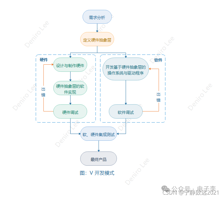
When designing and implementing the two functions of BSP, the following two different methods should be adopted:
(1) Implementing the initialization operations in BSP from the “bottom-up” approach: starting from chip-level initialization to system initialization;
(2) Designing hardware-related drivers from the “top-down” approach: starting from the API, then to the general device drivers within the operating system, then to the hardware-related device drivers within the BSP, and finally to the specific hardware devices at the bottom layer.
3.5 Limitations and Improvements of BSP Design Methods
From the two design methods introduced above, it can be seen that the current design and implementation of BSP mainly involve modifying certain specific files. This method is somewhat primitive, as it requires designers to understand the various components of BSP and the specific meanings of the corresponding files and related parameters, while also necessitating a comprehensive understanding of software and hardware. Directly modifying relevant files can easily lead to inconsistencies in code, increasing hidden errors in software design, and subsequently complicating system debugging and code maintenance. As the underlying hardware functions become increasingly complex, the content involved in developing BSP is also growing. The shortcomings of this primitive method are becoming more pronounced. Innovating BSP design methods and tools has become an increasingly prominent issue.
A feasible solution to this problem is to design a graphical interface BSP development guide that guides designers step by step through the design and development of BSP, ultimately generating the corresponding BSP files without direct modification of the source files by designers. This not only significantly shortens the BSP development cycle and reduces code inconsistencies, but also simplifies system debugging, troubleshooting, and maintenance. Therefore, this method is a trend and research direction for BSP design in the embedded field at present. However, due to the diversity of hardware environments in embedded systems, several key issues still need to be resolved in the implementation of the design guide.
————————————————
Disclaimer: The source of this article is CSDN’s BinaryStarXin. This account maintains neutrality regarding all original and reprinted articles, and the articles are pushed solely for readers’ learning and communication. The copyrights of articles, images, etc., belong to the original authors. If there is any infringement, please contact us for deletion.
Original link: https://blog.csdn.net/m0_46577050/article/details/121050054