Introduction
Back when I was in elementary school, I would run around the neighborhood with a paper lantern every New Year.
With the Spring Festival approaching, I decided to make a lantern for myself, which would also contribute a theme to my Arduino project.
As for the functions of the lantern, I considered many possibilities, including lighting up when picked up, voice control, broadcasting New Year blessings, and timed switches.
Faced with these options, I chose the simple and practical function of “lighting up when picked up” based on my technical level.My goal is to achieve the effect: when I pick up the lantern, the light will turn on; when I put it down, the light will turn off.
A lantern with such functionality can be hung in a fixed place and will light up when the wind blows.
I can also pick up the lantern to light it up and carry it around;when I place the lantern on a table or the ground, it can automatically turn off without me having to toggle a switch.
To meet the above requirements, I can use an accelerometer to detect whether the lantern has been picked up, and control the LED light in the lantern using an Arduino Nano development board.
Experimental Materials
Lantern shell (purchased online)
ADXL345 accelerometer
Arduino Nano development board
Breadboard
Jumper wires
Switch
PN2222A transistor
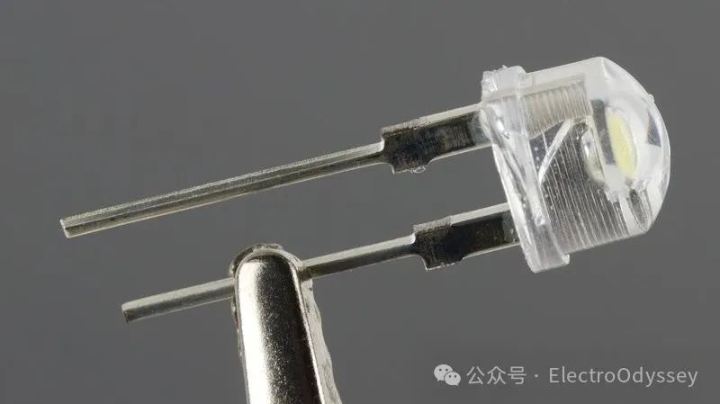
0.25W 3V white LED
Fishing line
Needle-nose pliers
7.2V lithium battery
Computer
Data cable
Soldering tools
Safety goggles
Theoretical Preparation – Hardware Part
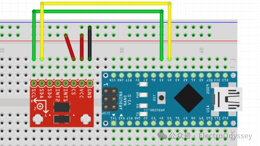
The ADXL345 accelerometer can send signals to the Arduino Nano via the I2C communication protocol.The I2C protocol requires two connection lines: Serial Clock Line (SCL) and Bidirectional Serial Data Line (SDA).
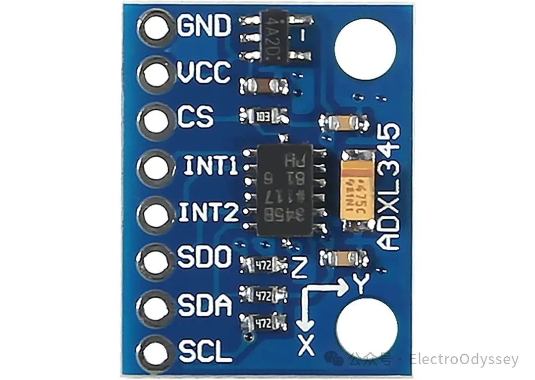
ADXL345 Accelerometer Module
The I2C ports of the ADXL345 can be directly referenced according to the markings on the circuit board.The I2C ports of the Arduino Nano are A4 (connects to Bidirectional Serial Data Line) and A5 (connects to Serial Clock Line).
Since this circuit will only communicate with the accelerometer, the sensor’s Chip Select (CS) interface can be directly connected to a 5V high level to keep it selected. The other two ports on the sensor, VCC and GND, must be connected to the positive and negative terminals of the power supply, respectively.
To ensure brightness, this circuit uses a 0.25W 3V LED, which requires around 80mA of current. However, each digital output port on the development board can provide a maximum of 40mA of current, which is insufficient to achieve the expected brightness for the LED.
Therefore, I connected the LED directly to the 5V power circuit of the development board, and built a transistor circuit to control the LED light.
This circuit allows me to control a large current from the collector to the emitter with a small current from the base to the emitter, controlling the LED light without overloading the development board.
After confirming the design scheme for the sensor and LED light, I needed to consider the power supply issue. This circuit needs to be installed in the lantern for a long time and used in various locations. USB power supply is obviously not suitable for such a scenario.
To solve this, I found a 7.2V lithium battery, connected the positive terminal to the power input (Vin) of the Arduino Nano, and the negative terminal to the ground (GND) of the development board, allowing the board to operate normally without the data cable.
However, the battery’s wiring uses an XH2.54 male connector, which cannot be directly connected to the breadboard. To solve this problem, I found an XH2.54 socket and soldered a Dupont wire to each of the positive and negative terminals.
This way, the positive and negative terminals of the battery are connected to the breadboard via Dupont wires. Just connect the pins to the correct positions on the breadboard to successfully connect the power supply.
After the above process, the hardware part of the lantern core is complete. Next, I need to consider the software part.
Code Writing
Regrettably, I still have not fully understood the structure of the I2C communication protocol and cannot comprehend the I2C communication flow in the ADXL345 data manual.
To read data from the sensor, I copied a piece of code from the internet and uploaded it directly to the Arduino Nano.
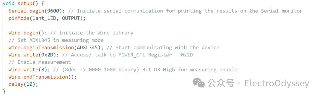
Code found online (partial)
Soon, the development board returned the correct sensor readings.
Then, I used the method learned in math class to calculate the length of the vector and converted the readings from the sensor’s x, y, and z axes into the magnitude of the acceleration vector.

While monitoring the values on the computer screen, I rotated the accelerometer and found that this value remained below 1.1 when stationary, while it would rise above 1.4 when accelerating upwards or shaking.
So, I set the trigger value for the sensing light to 1.2, allowing the development board to light up the LED when the lantern is lifted.
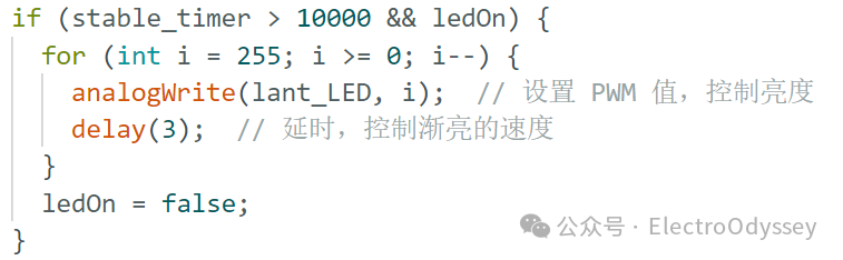
Finally, I added a few lines of code to make the lantern automatically turn off after being stationary for 10 seconds.
Debugging Phase
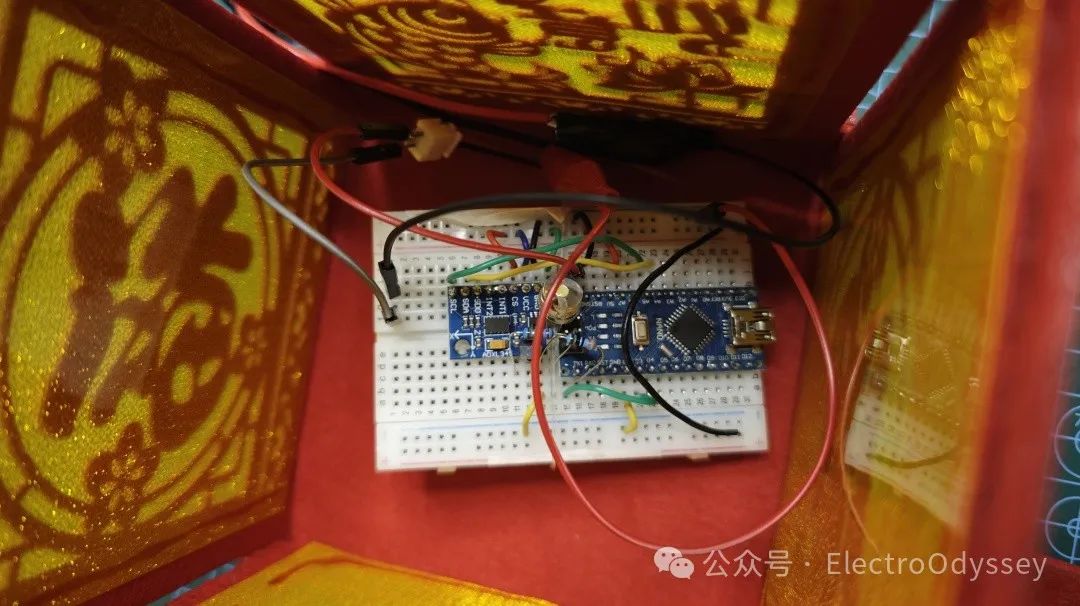
This is the version 1.0 of my lantern core.
In the following days, I successively added an energy-saving switch and a gradual light dimming effect, and tied the breadboard to the bottom of the lantern with a piece of fishing line.
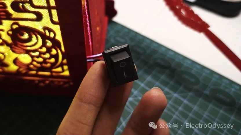
Worried that the Arduino Nano would drain the battery while in standby, I installed an energy-saving switch in the lantern core, allowing me to manually cut off power after using the lantern.
Then I placed the breadboard into the lantern shell for debugging and found that the breadboard was wobbling inside the lantern and could not maintain a fixed position. I used fishing line to tie the breadboard to the center of the lantern base.
Tying knots in fishing line is a laborious task. The surface of the fishing line is smooth and elastic. If not careful, the line will bounce out of the knot. Following a video online, it took me nearly half an hour to secure the breadboard.
After the final test, I covered the lantern’s lid.The lantern that lights up when picked up is finally complete.
Result Display
One More Thing
Although this lantern is themed for the Spring Festival, in order to reuse the electronic components inside, I may have to dismantle it before the holidays.