
MAKER: Action-Script/ Translator: QunWujin
Using a Raspberry Pi and a thermal printer to create an instant camera is not a difficult task. Many makers have already practiced similar projects.
In this project, I referenced other related projects and added my own ideas to create a satisfying Raspberry Pi instant camera. Let’s take a look together.
This project uses a Raspberry Pi and a thermal printer. Most other Raspberry Pi instant camera projects use Raspberry Pi 2 (currently not supporting Raspberry Pi 3 version), wide-angle lenses, and camera modules.
I chose the Raspberry Pi Zero W and a medium focal length lens.
The Raspberry Pi Zero W is compact and practical, including a camera interface and onboard Wi-Fi, as well as many other features.
Most Raspberry Pi camera modules come with wide-angle lenses. I chose the M12 lens, which has a field of view of 40°, achieving a similar effect to a 45mm full-frame camera, making the image more natural and less distorted. It supports remote control shooting due to its wireless connection.

Material List
Hardware:Raspberry Pi (Raspberry Pi) Zero W × 1 Mini TTL thermal printer × 1 Raspberry Pi camera module × 1 Mini camera (CSI) 15-pin soft ribbon cable × 1 M12 camera lens × 1 M12 board lens holder × 1 button × 15v/3.5A mobile power supply (minimum 3A) × 1 4700uF electrolytic capacitor × 1 right-angle USB adapter (male to female) × 1 12.1mm jack connected to USB adapter port × 1 adapter (2.1mm jack) × 1 single row pin × 1 single row socket × 1 double row pin connector × 3 breadboard × 1 wire × several screws M3 x 6mm (6mm~10mm) × 2 square nuts (M3 1.8mmx5.5mm) × 2 screws M2 x 6mm (6mm~10mm) × 2 thermal paper roll (57mm) × several 8GB MicroSD cards × 1 Mini HDMI adapter (ZERO W connecting to the monitor) × 1 Mini USB to USB (ZERO W connecting to keyboard) × 1 15v USB charger × 1 Prusa i3 mk3 3D printer × 1 cable crimper (SN-28B) × 1 pliers × 1 digital caliper × 1 screwdriver × several
Software:Fusion 360 Raspbian Jessie Lite ImageMagick
Software Setup and Code

In this step, you need a USB keyboard and HDMI display. Install the camera module to the Raspberry Pi, test and check if it works properly. Run the system setup with raspi-config:
$ sudo raspi-config
For this project, the following options are required:Interfacing Options -> Enable Camera Interfacing Options -> Disable Serial Advanced Options -> Expand Filesystem
Use raspi-config to set up the Wi-Fi connection. Use the network connection to upgrade the system and download the necessary software.Network Options -> Wi-fiYou can also enable SSH for remote access to the system and make quick changes.Interfacing Options -> Enable SSH
Install SoftwareYou can refer to this tutorial: learn.adafruit.com/instant-camera-using-raspberry-pi-and-thermal-printer
sudo apt updatesudo apt install git cups wiringpi build-essential libcups2-dev libcupsimage2-devInstall CUPS raster filter from Adafruit’s GitHub.
git clone https://github.com/adafruit/zj-58cd zj-58
make
sudo ./installInstall on the CUPS system and set the printer as the default.
Adjust the “baud rate” value to 9600 or 19200 depending on the specific printer. (My project uses 19200)
sudo lpadmin -p ZJ-58 -E -v serial:/dev/ttyAMA0?baud=19200 -m zjiang/ZJ-58.ppd
sudo lpoptions -d ZJ-58
Camera Script
sudo apt-get install imagemagickUse ImageMagick to enhance contrast and set the camera to default contrast and brightness. The shooting command sequence is as follows:
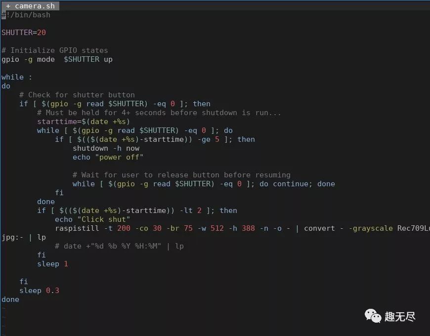
raspistill -t 200 -co 30 -br 75 -w 512 -h 388 -n -o - | convert - -grayscale Rec709Luminance -contrast jpg:- | lpThese are the best values for my parameters, you can modify them according to your situation.
I use the same button to take photos and shut down the system. The script requires a long press of 4 seconds. camera.sh (for the complete code, please click the original text at the end)
Automatically set the script to start when the system is powered on.Modify the file /etc/rc.local before the last “exit 0” line and execute the following command:
sh /home/pi/camera.sh
Use the path where the script file is saved.
Enable Serial Compatibility for Raspberry Pi Zero W
pi3-miniuart-bt switches the Bluetooth function of Raspberry Pi Zero W to use mini UART (ttyS0), and restores UART0/ttyAMA0 to GPIO14 and 15.
Disable onboard Bluetooth and restore UART0/ttyAMA0 through GPIO14 and 15, modify to:
sudo vim /boot/config.txtAdd to the end of the file
dtoverlay=pi3-disable-btDisable the system service that initializes the modem, not using UART:
sudo systemctl disable hciuartFor more information on this configuration, please refer to: https://www.raspberrypi.org/documentation/configuration/uart.md
3D Printed Shell
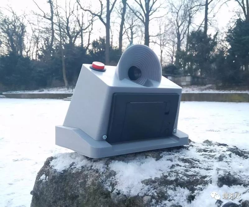
 The camera’s shell is tightly fitted, compact, and minimizes the design of screws.
The design is divided into three parts:
1. Bottom, mainly for installing the power supply.
2. Main part, installing the Raspberry Pi, printer, and most of the wiring.
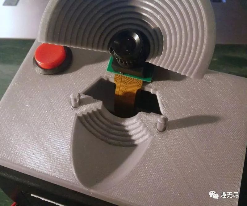
3. Lens barrel, mainly for installing the camera lens.
Download the files needed for printing from the project file library.https://maker.quwj.com/project/100


The main part and lens barrel are optimized mainly for printing functions and do not require support structures. The bottom of the shell is printed with internal support material as a single item. I made a sturdy sample to support the camera structure. STL files are provided in the project file library, you can print or modify them as needed.
Wiring

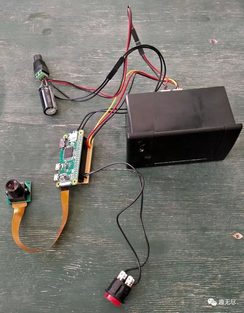

1. Solder the header pins to the IO interface of the Raspberry Pi. 2. Insert the Raspberry Pi into the breadboard and start testing the setup. 3. To connect components, I used 2Pin crimp terminals for separate connections. This way, components can be individually connected to the shell during assembly. Easy installation allows for convenient replacement when components fail or hardware is upgraded. 4. Connect the 4700uF capacitor to the + and – terminals using round connectors. This will help maintain stable voltage when the thermal printer is running. Ensure that the negative leg (shorter) of the capacitor connects to the negative terminal instead of the other end. 5. Connect the round connector and capacitor, printer power line, and Raspberry Pi Zero W. 6. Solder +5V to PP1 and ground from the power supply to PP6 on the back of the circuit board, just below the USB power supply, to power the Raspberry Pi. 7. Solder the dual-row socket to the breadboard, connecting Raspberry Pi IO pins. On the breadboard, you can connect the button and printer data line. 8. Connect the button to ground GND (pin 34) and BCM20 (pin 38) 9. The printer connection is as follows:
Printer GND –> Raspberry Pi GND (pin 6) Printer RX –> Raspberry Pi TXD (pin 8, BCM14, UART send) Printer TX –> Raspberry Pi RXD (pin 10, BCM15, UART receive)
Raspberry Pi 40Pin pinout
Assembly

The assembly process is very simple.


The mobile power supply is fixed at the bottom of the case. But it can be easily charged, removed, or replaced.
 I printed several pins to connect the Raspberry Pi board to the shell and connected the lens to the rest of the shell.
 There is not much space for all cables and components. You should make good use of space and arrange the internal layout well. To close the case, the bottom and main parts have two matching latches. There is a screw bag on the front to secure the box.


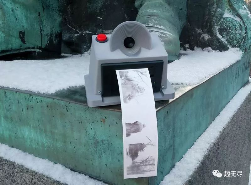
Done, you can start taking pictures now!


What?! Do you still need beauty filters? Just wait… In the world of makers, nothing is impossible!
The project file library address:
http://maker.quwj.com/project/100
via instructables.com/id/Portable-Instant-Pi-Camera
Links in the article can be clicked to read the original text at the end

More exciting content
DIY “Pop” sound control switch with Raspberry Pi
Create a laser cat toy with ESP8266
Make a fully automatic color sorter with Arduino
Raspberry Pi 3 Model A+ released
Homemade rechargeable 18650 lithium battery pack with infinite expansion
Make an LED scrolling display with Arduino
