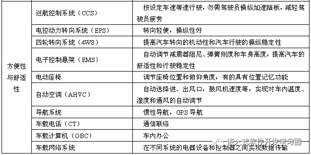
The Development of Automotive Electronic Control Technology
The rapid development of automotive electronic control technology mainly depends on three factors: first, the rapid advancement of transistor technology, large-scale integrated circuit technology, computer technology, and network technology has continuously reduced costs and enhanced control functions, providing favorable conditions for the development of automotive electronic control technology; second, increasingly stringent regulations set by governments around the world force automobile manufacturers to adopt advanced electronic control technologies to meet regulatory requirements regarding fuel economy, safety, and emissions performance; third, the increasing demand from users for automotive safety, comfort, power, and economy prompts automobile manufacturers to adopt more electronic control technologies to enhance their products’ competitiveness in the market.
The development process of automotive electronic control technology can be roughly divided into three stages: electronic circuit control, microcomputer control, and onboard local area network control.
• First Stage (1953–1975): Analog electronic circuit control stage, where discrete electronic components or integrated circuits were used to form electronic controllers for control. Automotive electronic devices mainly used discrete electronic components to form electronic controllers, marking the dawn of the automotive electronics era.
• Second Stage (1976–1999): Microcomputer control stage, where analog or digital computers were used for control, and control technology developed towards intelligence. Automotive electronic devices commonly used 8-bit, 16-bit, or 32-bit microprocessors for control, primarily developing dedicated independent control systems and integrated control systems.
• Third Stage (2000 to Present): Onboard local area network control stage, where onboard LAN (Local Area Network) is used to control automotive electrical and electronic control systems. Mid-to-high-end cars both domestically and internationally have begun to adopt onboard LAN technology.
Trends in Automotive Electronic Control Technology
1. Integration of Control Systems
Modern vehicles increasingly integrate single control systems into centralized control systems, which simplifies the overall system and facilitates comprehensive coordination control of complex systems with multiple variables and objectives. However, integration of control systems requires microprocessors with greater computational power and faster speeds, leading to the development of microprocessors from 8-bit, 16-bit, and 32-bit to 64-bit.
2. Networked Information Transmission
Due to the sharp increase in the number of electronic devices in vehicles, automotive circuits are becoming increasingly complex. To reduce the number of connection wires, modern vehicles widely adopt onboard network technology, transforming the previous point-to-point dedicated line system into a multi-use line system. Network technology can connect various electronic control units, intelligent sensors, and smart instruments within the vehicle, forming an internal controller local area network that enables information resource sharing between systems. This not only simplifies wiring, reduces the number of electrical nodes and the amount of wiring, but also increases the reliability of information transmission.
3. Intelligence of Vehicles and Traffic
Intelligent vehicles are comprehensive systems that integrate environmental perception, planning and decision-making, and multi-level assisted driving functionalities. They utilize technologies such as computers, intelligent sensors, information fusion, communication, artificial intelligence, and automatic control, making them typical high-tech composites.
Intelligent Transportation Systems (ITS) effectively integrate advanced information technology, communication technology, sensing technology, control technology, and computer technology into the entire transportation management system, establishing a real-time, accurate, and efficient comprehensive transportation and management system. The combination of intelligent transportation technology with intelligent vehicle technology can achieve automatic selection of the best driving routes and autonomous driving of vehicles. The intelligence of vehicles and traffic represents the future direction of automotive and transportation development.
4. Modular Design of Electronic Control Systems
Modular design refers to the development of various products with multiple functions without the need for separate designs for each product. Instead, multiple modules are carefully designed and combined in different ways to form different products, addressing the conflicts between product variety, specifications, manufacturing cycles, and costs. With the increasing competition in the automotive market, to meet users’ personalized needs, automobile manufacturers need to introduce more new models, and the development cycle of new models is becoming shorter. The use of modular design technology for electronic control systems can shorten the development cycle, improve the quality of developed products, reduce development costs, and effectively enhance the reliability of automotive electronic control systems and the entire vehicle.
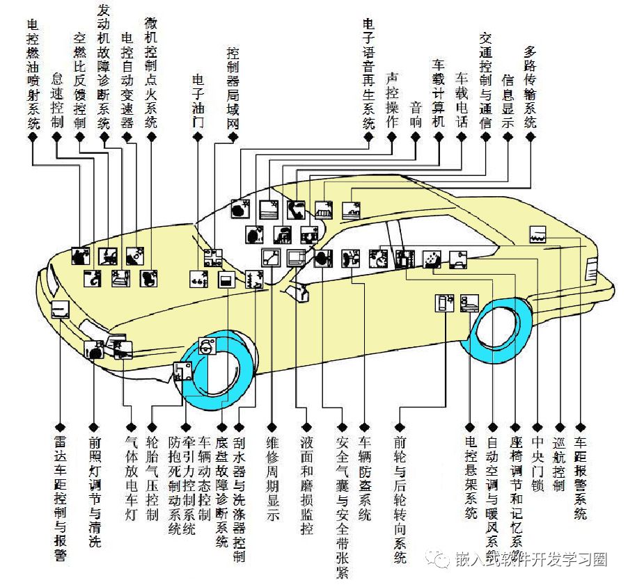
Basic Components of Automotive Electronic Control Systems
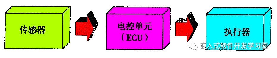
Each electronic control system in a vehicle consists of three parts: sensors and switches, electronic control units (ECU), and actuators (executive components), which are interconnected through wires to form an electronic control system.
1. Sensors
(1) Flow Sensor
Detects the flow of gases and liquids being measured, such as the air flow sensor used in the engine’s electronic fuel injection system; refrigerant flow sensor used in automatic air conditioning systems, etc.
(2) Position Sensor
Detects the angle of rotating objects or the displacement of moving objects, such as the crankshaft position sensor, camshaft position sensor, and throttle position sensor used in the engine’s electronic fuel injection and microcomputer-controlled ignition systems; steering wheel angle sensor for electronic stability programs; body height sensor for electronic control suspension systems; and EGR valve position sensor for exhaust gas recirculation systems, etc.
(3) Pressure Sensor
Detects the pressure of the measured medium, such as the manifold absolute pressure sensor, atmospheric pressure sensor, and exhaust pressure sensor used in the engine’s electronic fuel injection system; and oil pressure sensor in the anti-lock braking system, etc.
(4) Temperature Sensor
Detects the temperature of the measured medium, such as the engine coolant temperature sensor, intake temperature sensor, exhaust temperature sensor, and fuel temperature sensor used in the engine’s electronic fuel injection and microcomputer-controlled ignition systems; and the interior temperature sensor used in automatic air conditioning control systems, etc.
(5) Concentration Sensor
Detects the concentration of the measured medium, such as the oxygen sensor used in the engine’s electronic fuel injection system; and alcohol concentration sensor used in safety control systems, etc.
(6) Speed Sensor
Detects the speed of rotating objects or moving objects, such as the engine speed sensor used in electronic fuel injection and microcomputer-controlled ignition systems; wheel speed sensor used in anti-lock braking systems; and vehicle speed sensor used in electronic automatic transmission systems, etc.
(7) Acceleration Sensor
Detects the acceleration of the measured object, such as longitudinal and lateral acceleration sensors used in electronic stability programs; and vertical acceleration sensor used in electronic control suspension systems, etc.
2. Electronic Control Unit (ECU)
The automotive electronic control unit, abbreviated as ECU, is also known as the automotive electronic controller or automotive electronic control component, commonly referred to as the “car computer.”
The ECU is an electronic control device centered around a microcontroller, with powerful capabilities for mathematical computation, logical judgment, data processing, and data management.
The ECU is the control center of the automotive electronic control system, primarily responsible for analyzing and processing various information collected by sensors and issuing control commands to the controlled devices (i.e., actuators or executive components).
3. Actuators
Actuators, also known as executive components, are the executing mechanisms of the electronic control system. The function of actuators is to receive commands from the ECU and perform specific actions. The actuators in automotive electronic control systems typically include electric motors, solenoid valves, etc. The number and type of actuators used vary with different automotive electronic control systems.
For example, the actuators in the engine’s electronic fuel injection system include electric fuel pumps and solenoid injectors; the actuator in the engine idle control system is the idle control valve; the actuator in the gasoline vapor pollution control system is the activated carbon canister solenoid valve; the actuators in the microcomputer-controlled ignition system include the ignition controller and ignition coil; the actuators in the anti-lock braking system include two-way two-port solenoid valves or three-way three-port solenoid valves, and return pump motors; the actuator in the airbag system is the airbag igniter; the actuators in the electronic automatic transmission system include shift solenoid valves, oil pressure control solenoid valves, and lock solenoid valves; and the actuators in the electronic control suspension system include air compressors, shock absorber damping and spring stiffness adjustment motors, and height control solenoid valves, etc.
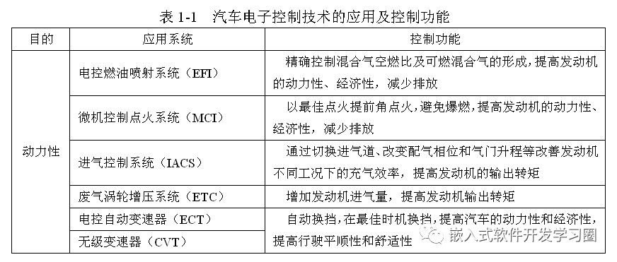
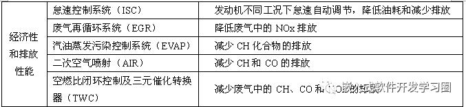
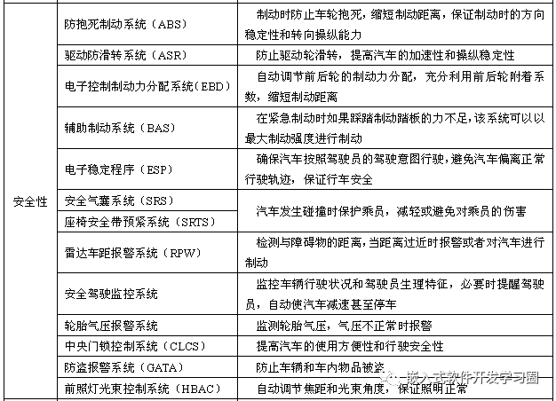
Engine Electronic Control System
Classification and Basic Composition of Electronic Fuel Injection Systems
1. Classification of Electronic Fuel Injection Systems
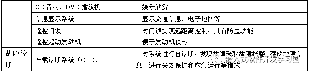
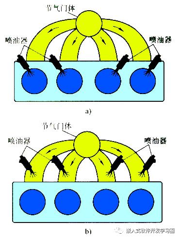
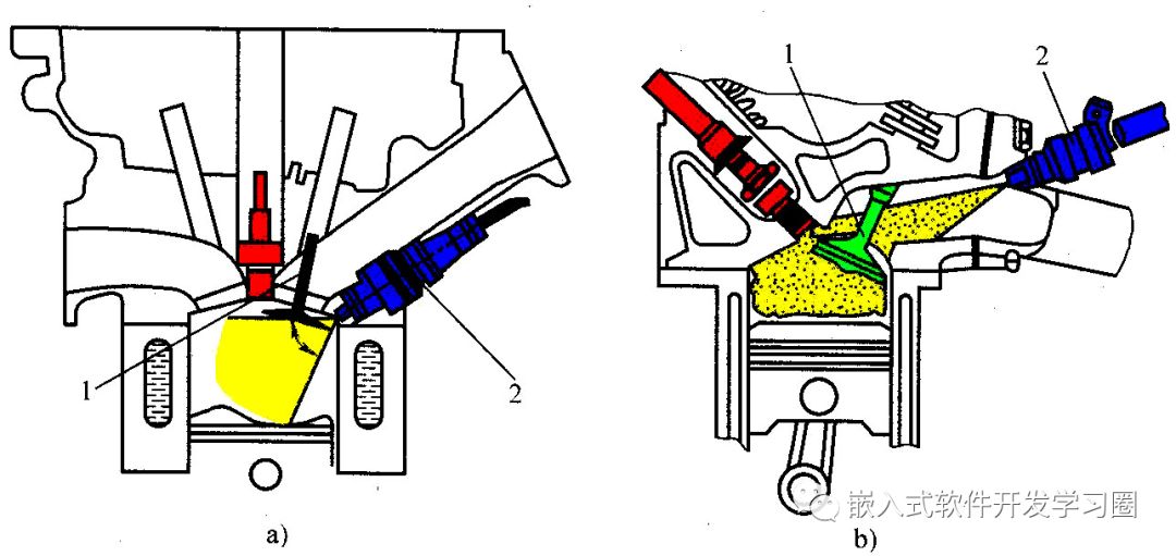
(1) Classification by Fuel Injection Location
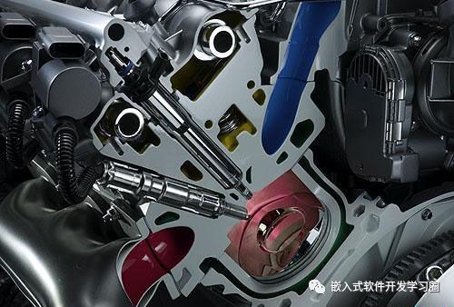
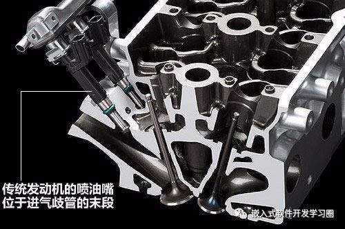
According to the different locations where fuel injectors inject fuel, electronic fuel injection systems can be classified into direct injection and port injection types.
(2) Classification by Air Intake Measurement Method
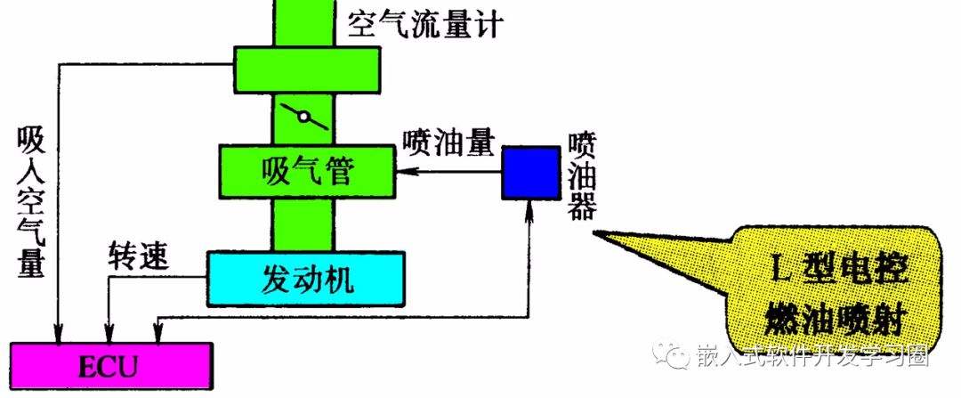
According to the different methods of measuring air intake, electronic fuel injection systems can be classified into D-type (speed-density control type) and L-type (mass flow control type).
D-type electronic fuel injection system composition

L-type electronic fuel injection system composition
2. Basic Composition of Electronic Fuel Injection Systems
Electronic fuel injection systems mainly consist of an air supply system, fuel supply system, and electronic control system.
(1) Air Supply System
The function of the air supply system is to provide the necessary air for the formation of the combustible mixture for the engine and to measure the amount of air entering the cylinder. The air supply system mainly consists of air filters, air flow sensors (L-type) or manifold absolute pressure sensors (D-type), throttle bodies, throttle position sensors, intake manifolds, etc. Additionally, the intake temperature sensor and idle control valve in the idle control system are also installed in the air supply system.
(2) Fuel Supply System
The function of the fuel supply system is to supply fuel to the engine’s cylinders for combustion of the mixture, consisting of the fuel tank, electric fuel pump, fuel distribution pipe, fuel filter, pressure regulator, injectors, and return pipe. Fuel is pumped from the tank by the fuel pump, and the fuel under certain pressure flows through the fuel filter to the fuel distribution pipe, which delivers fuel to each injector. The injector opens the fuel valve based on the ECU’s injection command, releasing an appropriate amount of fuel to mix with air and form a combustible mixture.
(3) Electronic Control System
The electronic control system consists of the electronic components that function in various systems of the engine. The hardware structure of the electronic control system generally consists of sensors, electronic control units (ECU), and actuators.
Air Supply System
1. Air Flow Sensor
The air flow sensor detects the amount of air entering the engine and converts the air flow information into an electrical signal input to the ECU, which uses it to calculate the injection time (i.e., injection amount) and ignition timing. The air flow signal is the primary basis for the control unit to calculate the injection time and ignition timing.
The air flow sensor comes in various types, including vane-type, Karman vortex-type, and hot wire or hot film type. Among these, the vane-type and Karman vortex-type are volume flow types, while the hot wire and hot film types can directly measure the mass flow of air by electronic components, avoiding measurement errors caused by altitude changes, thus being classified as mass flow types.
(1) Hot Wire Air Flow Sensor
An electric heating element placed in the air passage experiences a temperature drop due to heat transfer with the air. When the air flow is large, more heat is carried away, requiring more current to maintain the temperature of the heating element; conversely, when the air flow is small, less current is needed. The hot wire (or hot film) air flow sensor operates based on this principle to detect air flow.
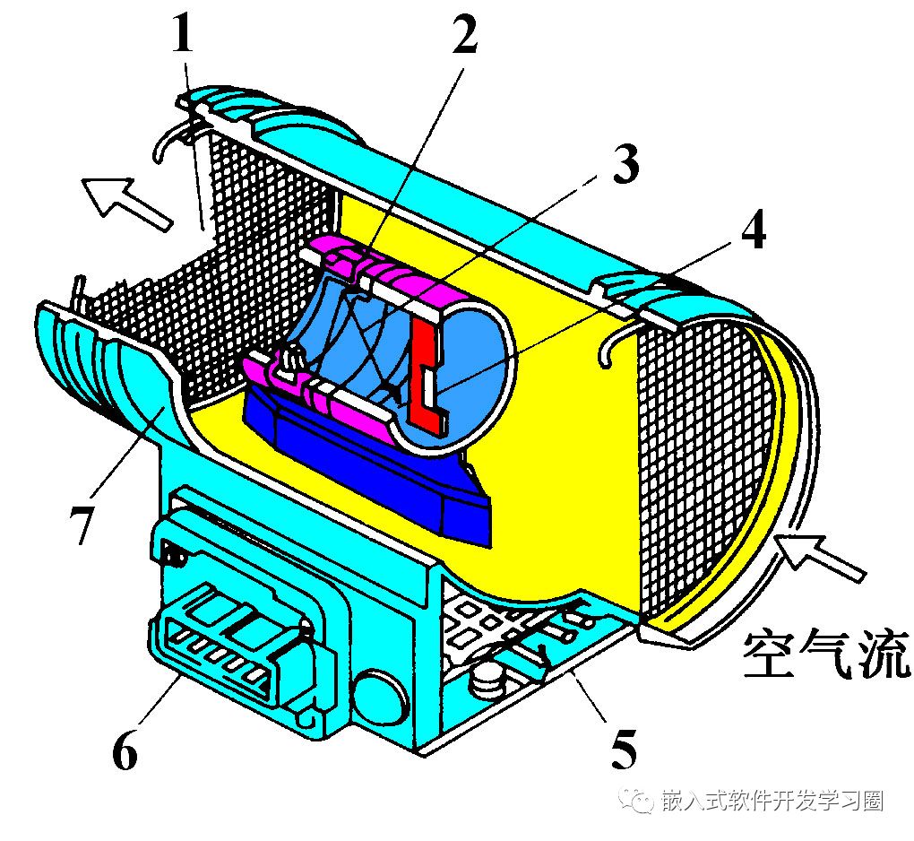
1—Protective mesh 2—Sampling tube 3—Platinum wire (hot wire) 4—Temperature compensation resistor (cold wire) 5—Control circuit board 6—Electrical connector 7—Housing
A hot wire air flow sensor circuit with a self-cleaning heating resistor set separately from the single-arm bridge.
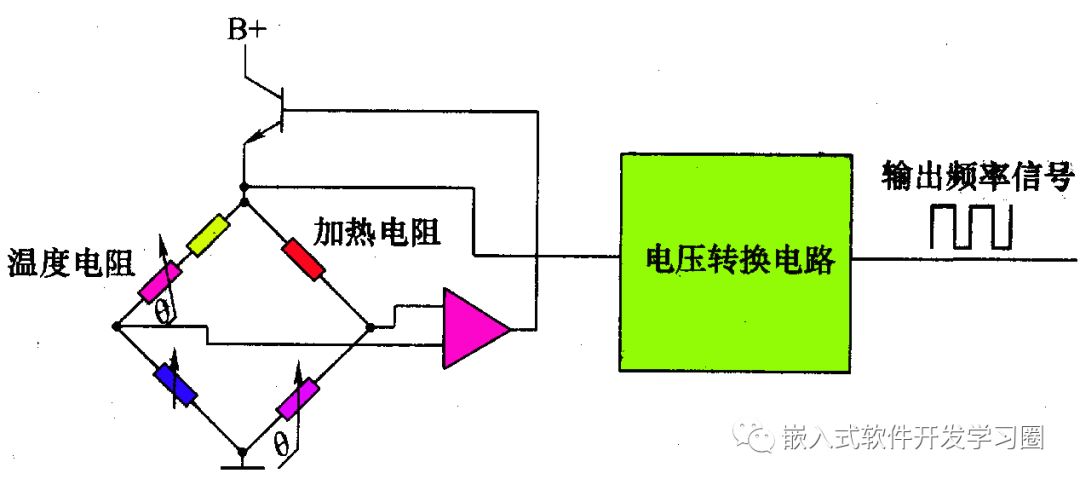
The working principle of the hot wire air flow sensor from General Motors is essentially the same as described above, but General Motors’ hot wire air flow sensor converts the output signal to a frequency square wave signal, and the frequency change trend increases with the increase in air flow (the average frequency at idle is 32Hz, while at wide open throttle, the frequency is 150Hz).

(2) Hot Film Air Flow Sensor
The heating element is made of a platinum thin film, hence the name hot film resistor. A rectangular sheath (equivalent to a sampling tube) is set in the air passage inside the sensor, with the hot film resistor located within the sheath. To prevent dirt from accumulating on the hot film resistor and affecting measurement accuracy, an air filter is placed at the air inlet side of the sheath to filter out dirt in the air.
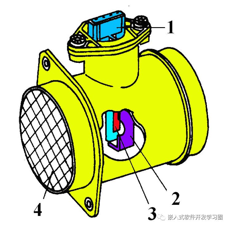
1—Connector 2—Sheath 3—Platinum film 4—Protective mesh
2. Manifold Absolute Pressure Sensor
In D-type fuel injection systems, the manifold absolute pressure sensor converts the absolute pressure (vacuum level) inside the engine’s intake manifold into a voltage signal, which is sent to the ECU along with the engine speed signal. The ECU calculates the air flow based on the absolute pressure inside the intake manifold and the engine speed signal, serving as the basis for determining the basic fuel injection amount and ignition timing. Thus, unlike the air flow sensor, which directly measures the engine’s intake amount, the manifold absolute pressure sensor is an indirect measurement sensor for the engine’s intake amount.
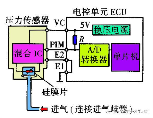
The structure of the piezoresistive type manifold absolute pressure sensor is shown in the figure, mainly consisting of a silicon diaphragm, vacuum chamber, mixed integrated circuit, vacuum tube connector, wire harness connector, and housing. The installation position of the manifold absolute pressure sensor is relatively flexible; as long as the intake pressure between the throttle and the intake manifold is introduced into the sensor’s vacuum chamber, the sensor can be placed anywhere.
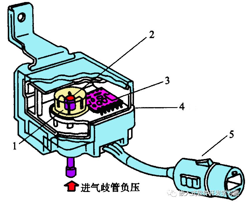
1—Vacuum chamber 2—Silicon diaphragm 3—Mixed integrated circuit 4—Housing 5—Wire harness connector
The length and width of the silicon diaphragm are approximately 3mm, with a thickness of about 16µm. A thin film with a diameter of 2mm and a thickness of about 5µm is made in the center of the thin silicon diaphragm using an etching method. On the surface of the thin silicon diaphragm, four strain resistors of equal resistance value are made using integrated circuit processing technology and surface diffusion technology (diffusion boron), which are connected to form a Wheatstone bridge circuit, and are then connected to the signal amplification circuit and temperature compensation circuit in the sensor.
1—Lead terminal 2—Housing 3—Silicon cup 4—Vacuum chamber 5—Silicon diaphragm 6—Solder seal
7—Strain resistor 8—Gold wire electrode 9—Electrode lead 10—Base 11—Vacuum tube
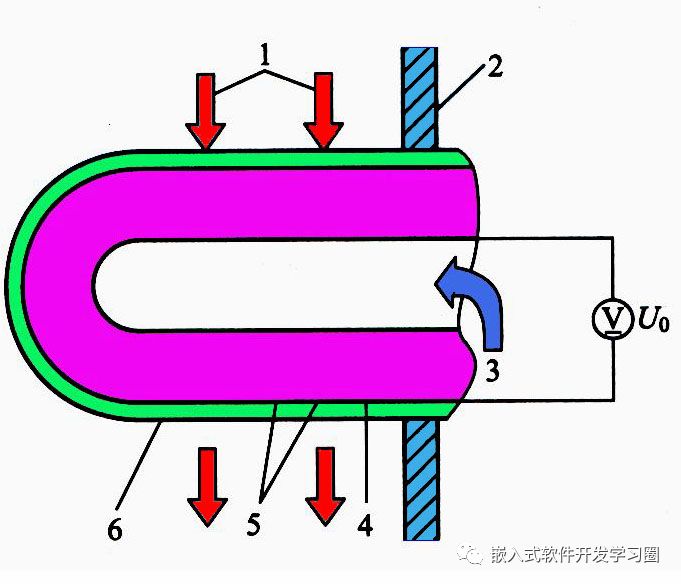
The working principle of the piezoresistive type manifold absolute pressure sensor is as follows: one side of the silicon diaphragm is connected to the vacuum chamber, while the other side is connected to the intake manifold pressure. When the engine operates, the intake pressure entering the manifold acts on the silicon diaphragm, causing it to deform under stress. Under this stress, the resistance of the strain resistors changes, leading to a change in resistance value, which disrupts the balance of resistance values in the Wheatstone bridge.
When a certain voltage or current is input to the input terminal of the bridge, a variable signal voltage or signal current can be obtained at the output terminal of the bridge. Based on the magnitude of the signal voltage or signal current, the pressure in the manifold can be calculated. When the structure of the sensor and the input power supply voltage Ucc are fixed, the output voltage U0 is proportional to the pressure acting on the circular silicon diaphragm; that is, the higher the pressure, the higher the output voltage.

3. Throttle Position Sensor
The throttle position sensor is installed at one end of the throttle shaft in the throttle body. Traditionally, it is controlled by the driver operating the throttle pedal via a cable to adjust the throttle opening. The throttle position sensor converts the throttle opening into an electrical signal sent to the ECU, which determines the operating condition of the engine and controls the injection timing based on the mixture concentration requirements under different engine conditions.
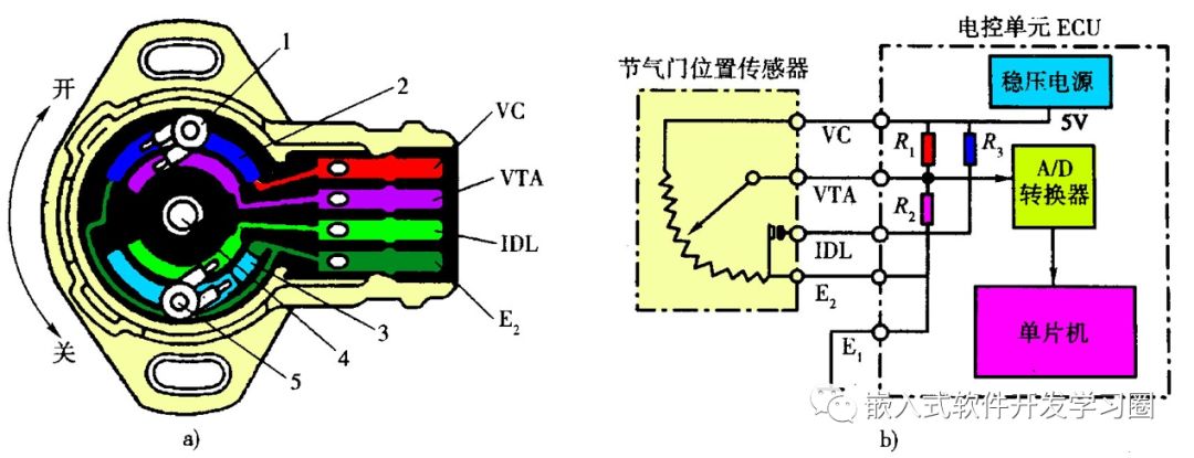
1—Variable resistor sliding contact 2—Power voltage input terminal (5V) 3—Insulation component 4—Throttle shaft 5—Idle contact
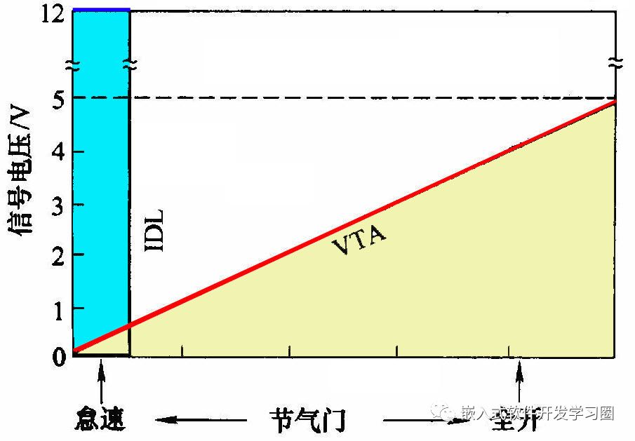
The output characteristics of the combined throttle position sensor are shown in the figure. When the throttle is closed or the opening is less than 1.2º, the idle contact closes, and the output terminal IDL outputs a low level (0V). When the throttle opening is greater than 1.2º, the idle contact opens, and the output terminal IDL outputs a high level (5V). As the throttle opening changes, the sliding arm of the variable resistor rotates with the throttle shaft, causing the signal voltage between the output terminal VTA and E2 to change. The greater the throttle opening, the higher the output voltage. The linear signal output by the sensor is converted into a digital signal by the A/D converter before being input to the ECU.
The Volkswagen engine control system often uses a combined throttle body, which integrates the contact type and linear variable resistor throttle position sensor with the throttle controller, eliminating the idle bypass and simplifying the structure.
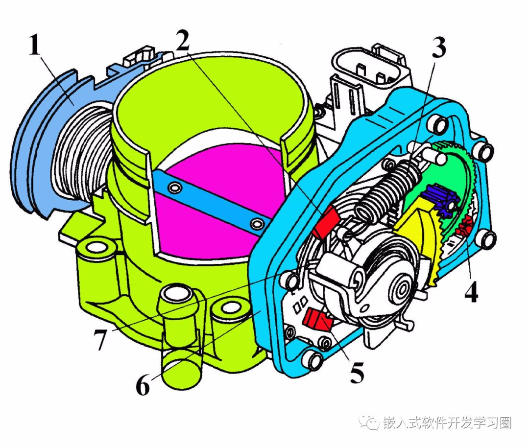
1—Throttle cable wheel 2—Throttle controller potentiometer 3—Emergency operation spring 4—Throttle controller (idle motor) 5—Throttle potentiometer 6—Integrated idle stability device 7—Idle switch
Temperature Sensors
Temperature is an important parameter reflecting the thermal load status of the automotive engine. To ensure that the control system can accurately control the engine, it is necessary to monitor the engine coolant temperature, intake temperature, and exhaust temperature at all times.
Temperature sensors can be classified into physical types (thermistors, thermistor ferrites) and structural types (bimetallic strips, paraffin types) based on their structure and physical properties. Modern vehicles widely use physical type temperature sensors, especially thermistor type temperature sensors, which have high sensitivity, good response characteristics, simple structure, and low cost. Therefore, the following mainly introduces thermistor type temperature sensors.
Commonly used thermistors include positive temperature coefficient thermistors (PTC) and negative temperature coefficient thermistors (NTC).
The structural form of thermistor type temperature sensors is shown in the figure, mainly consisting of thermistors, metal leads, connectors, and housing.
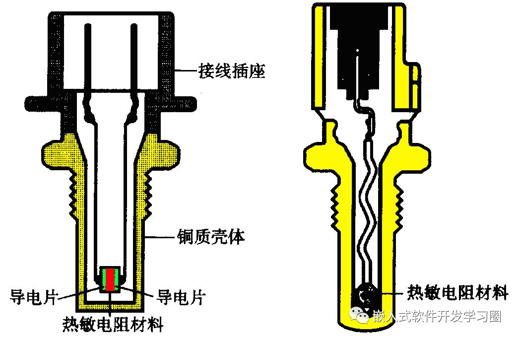
a) Two-terminal type b) Single-terminal type
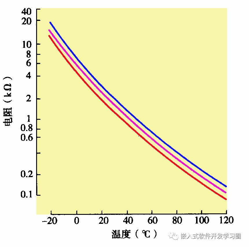
Negative temperature coefficient (NTC) thermistors have the characteristic of decreasing resistance with increasing temperature and increasing resistance with decreasing temperature, exhibiting a significant nonlinear relationship. For NTC thermistor type temperature sensors with a fixed structure, the relationship curve between resistance and temperature is shown in the figure.
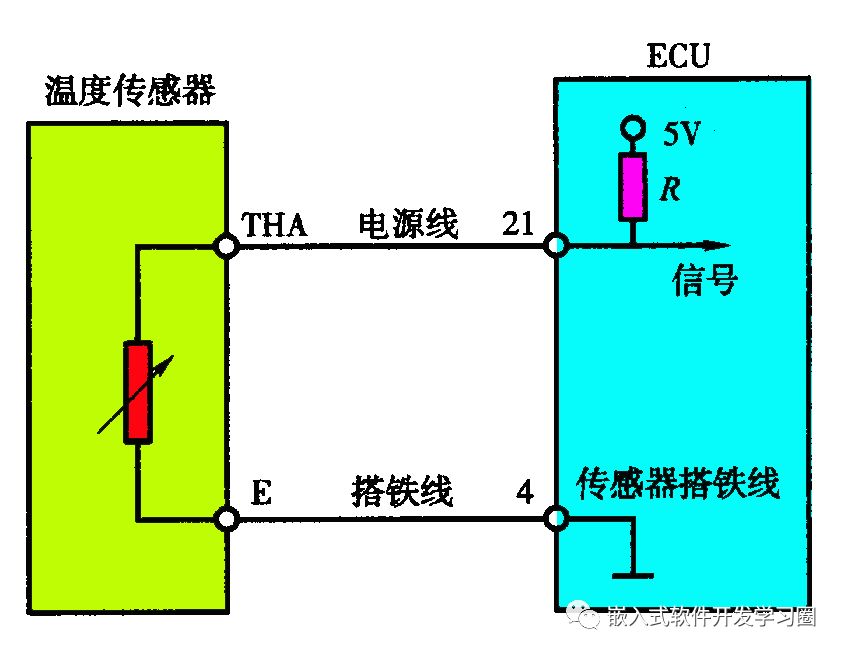
The working circuit of the temperature sensor is shown, where the two electrodes of the sensor are connected to the ECU socket via wires. The ECU has a voltage divider resistor in series, providing a stable voltage (generally 5V) to the thermistor and the voltage divider resistor. The signal voltage input to the ECU is equal to the voltage across the thermistor, which varies with the resistance of the thermistor. When the temperature of the measured object rises, the resistance of the sensor decreases, causing the voltage across the thermistor to decrease; conversely, when the temperature of the measured object decreases, the resistance of the sensor increases, causing the voltage across the thermistor to increase.
Fuel Supply System
The fuel supply system mainly consists of the fuel tank, fuel filter, electric fuel pump, supply pipe, return pipe, fuel distribution pipe, fuel pressure regulator, and injectors.
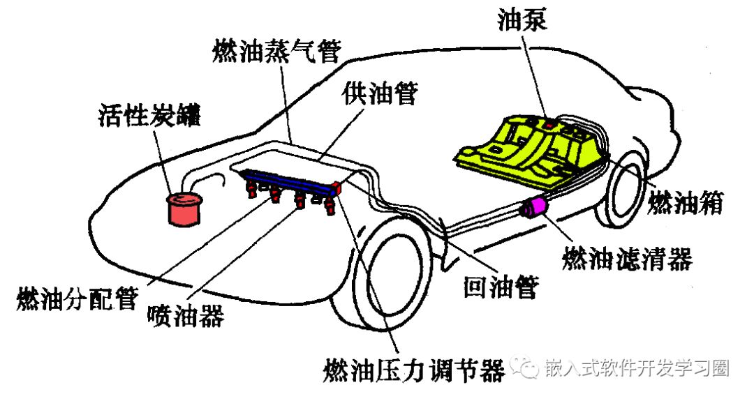
Layout of the fuel supply system in the vehicle
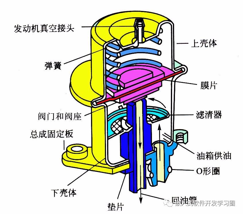
Typically, a non-return fuel supply system that minimizes the risk of gas blockage is used. The design of the non-return fuel supply system aims to prevent the flowing fuel from carrying heat back to the fuel tank, which would raise the fuel temperature and cause excessive evaporation. This system has two structural forms: one is to install the fuel pressure regulator inside the tank, as shown in the figure.
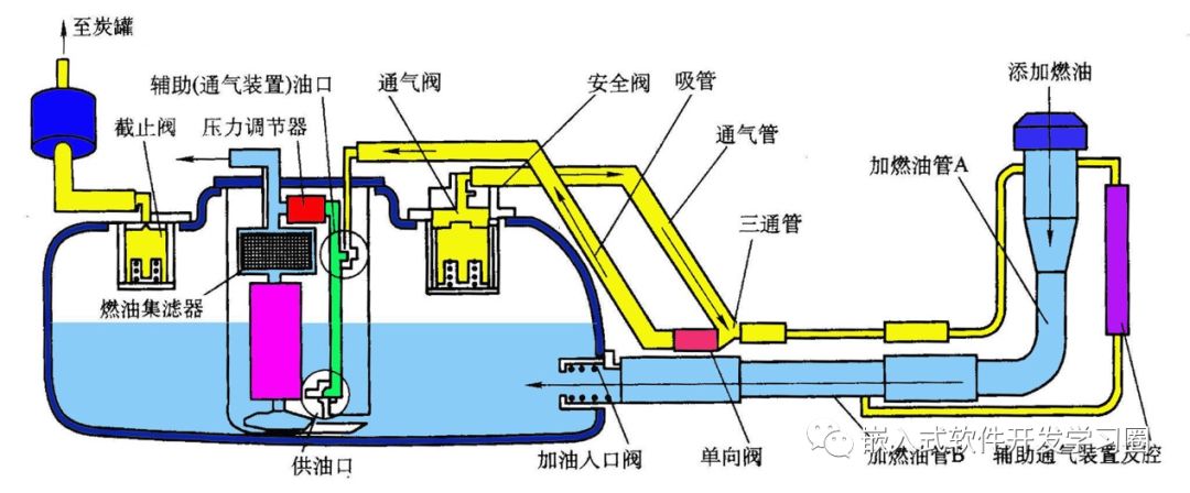
Non-return fuel supply system
The second is to eliminate the fuel pressure regulator, adding a pressure control valve to the fuel pump assembly to ensure that the pressure in the fuel distribution pipe remains at a constant value. The non-return fuel system includes a fuel pump and pressure controller.
Non-return fuel system fuel pump and pressure controller
Electric Fuel Pump
The function of the electric fuel pump is to draw fuel from the tank, pressurize it, and deliver it to the pipeline, working with the fuel pressure regulator to establish the appropriate system pressure (250–300kPa above manifold pressure), ultimately delivering fuel to the injectors. To prevent insufficient fuel supply to the engine and gas blockage due to high temperatures, the maximum output pressure of the pump needs to be around 470kPa, and its supply amount is much greater than the maximum fuel consumption of the engine. Excess fuel returns to the tank through the return pipe.
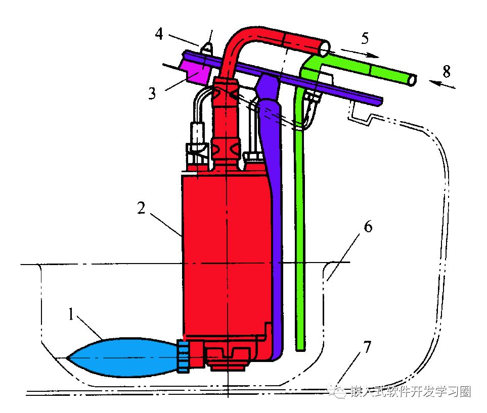
1—Inlet filter 2—Pump 3—Vibration isolation rubber 4—Bracket 5—Outlet pipe 6—Small tank 7—Fuel tank 8—Return pipe
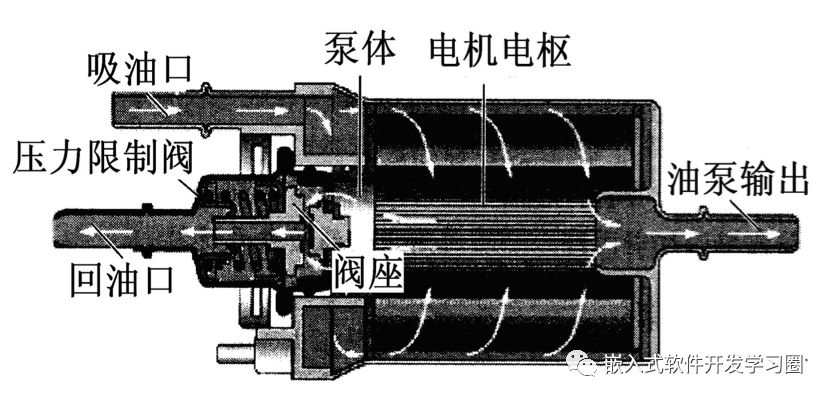
The internal structure of the electric fuel pump is shown in the figure, mainly consisting of a permanent magnet DC motor, pump, pressure limiting valve, one-way valve, and pump housing. The motor comprises a permanent magnet, armature, commutator, and brushes. The pump consists of a pump rotor and pump body, with the pump rotor fixed to the motor shaft, rotating with the motor.
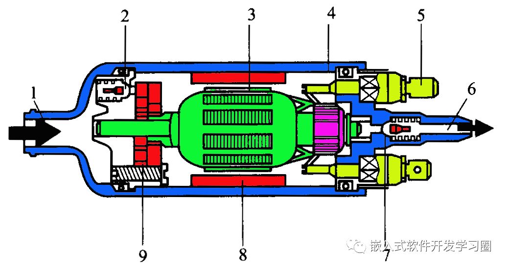
1—Inlet 2—Pressure limiting valve 3—Motor 4—Pump housing
5—Connector 6—Outlet 7—One-way valve 8—Permanent magnet 9—Pump body
Working Principle of the Electric Fuel Pump
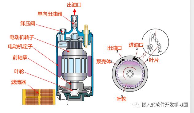
The control of the fuel pump is shown in the figure, which is a control circuit that utilizes the engine ECU to directly control the speed of the pump. When the engine operates, the ECU controls the power transistor VT to conduct and cut off at a high frequency (about 20KHz) based on fuel consumption, required return amount, and the temperature of the supply device, controlling the average voltage drop at point A (voltage divider value) to keep the pump at the required operating voltage. The working voltage of the pump varies in proportion to the engine load. In practical control, the working voltage of the pump mainly changes with the engine speed and injection pulse width.
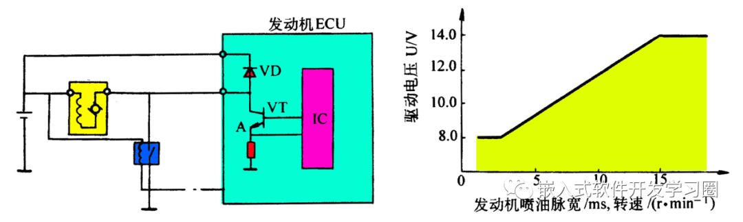
ECU direct control fuel pump control circuit Fuel pump working voltage characteristics
Fuel Distribution Pipe
The function of the fuel distribution pipe is to secure the injectors and fuel pressure regulator and distribute gasoline to each injector. The fuel distribution pipe has small holes at the connection points with the injectors to distribute fuel to each injector. Some engine models are equipped with fuel distribution pipes that have interfaces for connecting fuel pressure gauges (fuel pressure plugs) for measuring fuel pressure.
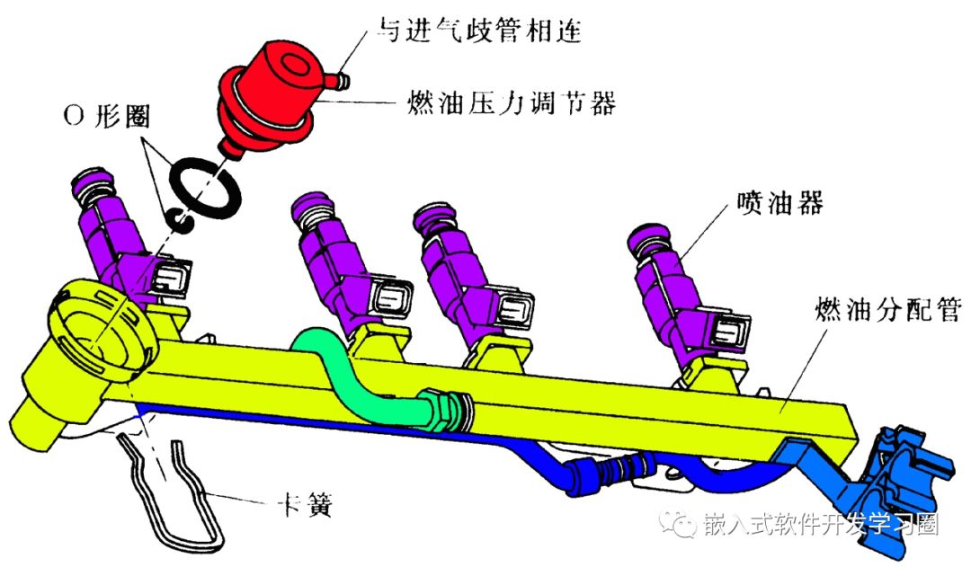
Fuel Pressure Regulator
The primary function of the fuel pressure regulator is to maintain a constant difference between the system pressure (i.e., the pressure in the supply pipe) and the intake manifold pressure, generally at 250–300kPa. This way, the amount of fuel sprayed from the injectors is uniquely determined by the opening time of the injectors.

Injectors
(1) Structural Principle
The injector is essentially an electromagnetic valve, as shown in the structure of the needle valve type injector. It mainly consists of the injector housing, injector nozzle, needle valve, armature on the needle valve, and the electromagnetic coil that generates electromagnetic attraction based on the injection pulse signal. When there is no current in the electromagnetic coil, the needle valve is pressed against the sealing cone valve seat at the injector outlet by a spring, preventing fuel injection. When the ECU sends an injection pulse signal to energize the electromagnetic coil, the magnetic field generated by the coil pulls the armature upwards, lifting the needle valve approximately 0.1mm, allowing fuel to flow out through the precision annular gap. When the ECU cuts off the circuit, the attraction disappears, and the return spring resets the needle valve, closing the injector and stopping the injection.
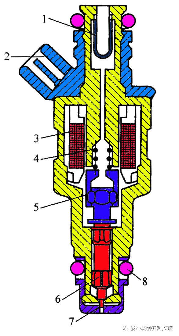
1—Inlet filter 2—Wiring connector 3—Electromagnetic coil 4—Return spring 5—Armature 6—Needle valve 7—Needle
(2) Control and Driving Methods
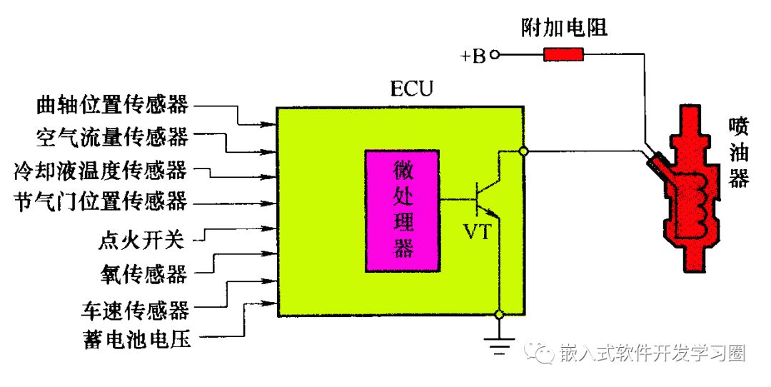
The engine electronic control unit (ECU) can control the injectors by controlling the power supply or ground connection of the injectors, as shown in the control circuit. During engine operation, the ECU determines the appropriate injection timing and pulse width based on various sensor input signals and provides a ground signal to the injector to start injection, cutting off the ground signal to stop injection.
The driving methods for injectors can be divided into current driving and voltage driving. Current driving is only suitable for low-resistance injectors (2–5Ω), while voltage driving can be used for both low-resistance and high-resistance injectors (12–17Ω). Current driving means that the engine ECU starts with a larger current (8A) to generate a strong attraction in the electromagnetic coil, ensuring good responsiveness of the injector, and then uses a smaller current (2A) to keep the needle valve open to prevent the injector coil from overheating and reduce power consumption. In the current driving circuit, there are no additional resistors, and low-resistance injectors are directly connected to the battery. Because there are no additional resistors, the circuit impedance is low, allowing the current through the injector coil to increase rapidly when the ECU sends a command to the injector, quickly opening the needle valve and shortening the injection delay time, resulting in better responsiveness.
Voltage driving means controlling the working voltage of the injector to control its operation. In the voltage driving circuit, when using high-resistance injectors, the battery voltage can be directly applied to the injector; while using low-resistance injectors, an additional resistor must be added to the circuit to divide the battery voltage before applying it to the injector, preventing excessive current in the electromagnetic coil from overheating and burning out.
Electronic Control System
The electronic control system can be simplified into three main components: sensors, electronic control units (ECU), and actuators.
Crankshaft Position Sensor and Camshaft Position Sensor
The crankshaft position sensor is used to detect the engine speed, crankshaft position (angle) signal, and the top dead center signal for the first cylinder and each cylinder during the compression stroke, serving as the main signal for controlling injection and ignition timing.
The structures used for crankshaft position sensors and camshaft position sensors vary by vehicle model and can be classified into three main types: magnetic induction type, Hall effect type, and photoelectric type.
(1) Magnetic Induction Crankshaft Position Sensor and Camshaft Position Sensor
① Working Principle. The basic structure and working principle of the magnetic induction sensor are shown in the figure. The sensor mainly consists of a signal rotor, sensing coil, permanent magnet, and magnetic yoke. The magnetic field lines traverse the path: permanent magnet N pole → air gap between the stator and rotor → rotor teeth → air gap between the rotor teeth and the stator magnetic head → magnetic head → magnetic plate → permanent magnet S pole. When the signal rotor rotates, the air gap in the magnetic circuit periodically changes, resulting in periodic changes in the magnetic resistance and the magnetic flux passing through the sensing coil (signal coil). According to the principle of electromagnetic induction, an alternating electromotive force will be induced in the sensing coil.
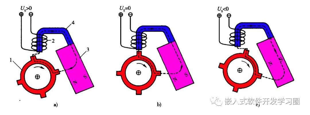
a) Tooth approaches magnetic head b) Tooth aligns with magnetic head c) Tooth leaves magnetic head
1—Signal rotor 2—Sensing coil 3—Permanent magnet 4—Magnetic yoke
As the signal rotor rotates, the air gap between the rotor teeth and the magnetic head decreases, increasing the magnetic flux, which increases the rate of change of magnetic flux, resulting in a positive induced electromotive force E (E > 0), as shown in the figure.
When the rotor teeth approach the edge of the magnetic head, the magnetic flux increases sharply, and the rate of change of magnetic flux is at its maximum, resulting in the highest induced electromotive force E, as indicated at point b in the curve. After the rotor passes point b, although the magnetic flux continues to increase, the rate of change of magnetic flux decreases, causing the induced electromotive force E to decrease.
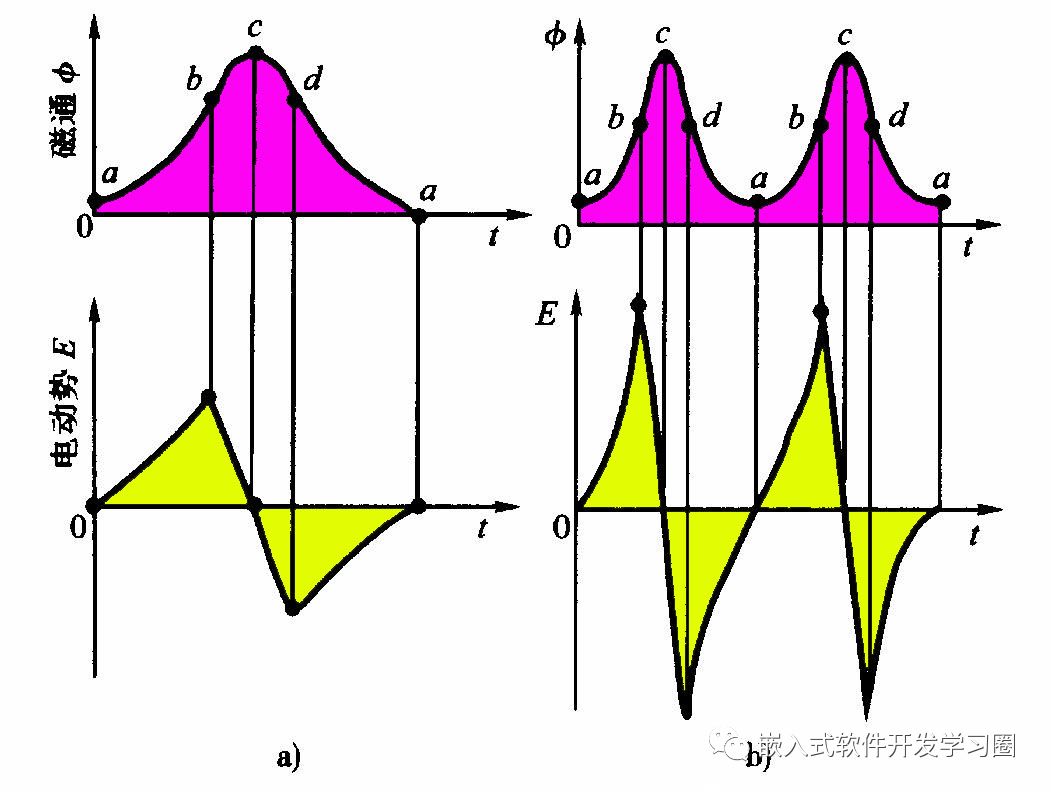
When the rotor rotates to the centerline of the tooth aligning with the centerline of the magnetic head, as shown in figure b, although the air gap is at its minimum and the magnetic resistance is minimal, the magnetic flux is at its maximum, but since the magnetic flux cannot continue to increase, the rate of change of magnetic flux is zero, resulting in an induced electromotive force E of zero, as shown at point c in the curve.
As the rotor continues to rotate clockwise, the gap between the teeth and the magnetic head increases, increasing the magnetic resistance and decreasing the magnetic flux, leading to a negative induced electromotive force E, as shown in curve cda. When the teeth are about to leave the edge of the magnetic head, the magnetic flux decreases sharply, and the rate of change of magnetic flux reaches its maximum negative value, resulting in the maximum negative induced electromotive force E at point d in the curve.
(2) Hall Effect Crankshaft Position Sensor and Camshaft Position Sensor
① Hall Effect
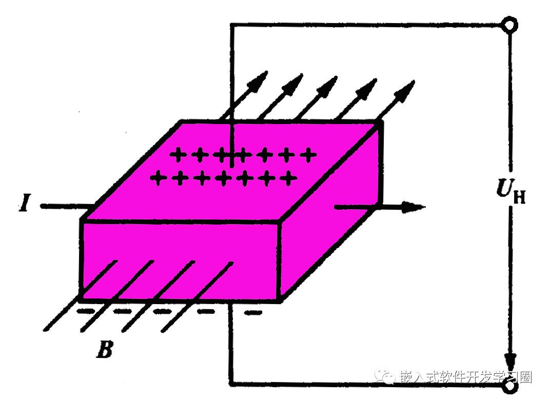
When a platinum conductor carrying current I is placed in a magnetic field with magnetic induction intensity B perpendicular to the field lines, a voltage UH will be generated on the transverse side of the platinum conductor, which is perpendicular to both the current direction and the magnetic field direction. UH is proportional to the current I through the semiconductor and the magnetic induction intensity B. When the magnetic field is removed, the voltage disappears immediately. This phenomenon is known as the Hall effect, and UH is referred to as the Hall voltage.
② Basic Structure
The basic structure of the Hall effect sensor is shown in the figure, mainly consisting of a triggering rotor, Hall integrated circuit, magnetic steel sheet (magnetic yoke), and permanent magnet. The triggering rotor is mounted on the rotor shaft, with blades manufactured on the rotor. As the triggering rotor rotates with the rotor shaft, the blades rotate between the Hall integrated circuit and the permanent magnet.
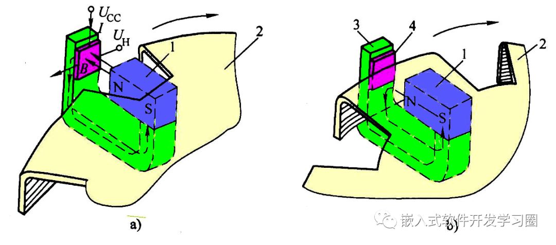
a) Blade leaves the gap, magnetic field saturates b) Blade enters the gap, magnetic field is bypassed
1—Permanent magnet 2—Triggering rotor 3—Magnetic yoke 4—Hall integrated circuit
③ Working Principle
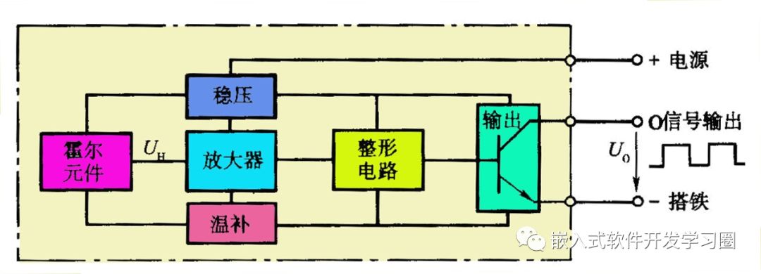
When the sensor shaft rotates, the blades of the triggering rotor pass through the gap between the Hall integrated circuit and the permanent magnet. When the blades leave the gap, the magnetic flux from the permanent magnet forms a loop through the Hall integrated circuit and magnetic steel sheet, as shown in the figure. At this time, the Hall element generates a voltage (UH=1.9~2.0V), and the transistor in the output stage of the Hall integrated circuit conducts, resulting in a low output signal voltage U0 of 0.1~0.3V, as shown in the figure.
Oxygen Sensor
The oxygen sensor is installed on the engine exhaust pipe and serves to monitor the oxygen content in the exhaust to obtain the air-fuel ratio signal, which is then converted into an electrical signal input to the ECU. The ECU uses the signal from the oxygen sensor to correct the injection timing, achieving air-fuel ratio feedback control (closed-loop control) to maintain the air-fuel ratio around the theoretical value of 14.7:1, thus optimizing the concentration of the mixture and reducing harmful emissions while saving fuel.
Oxygen sensors can be classified into zirconia (ZrO2) type and titanium dioxide (TiO2) type.
(1) Zirconia Oxygen Sensor
The structure of the zirconia oxygen sensor is shown in the figure, mainly consisting of a steel protective tube, steel housing, zirconia tube, heating element, electrode leads, waterproof sleeve, and wire harness connector.
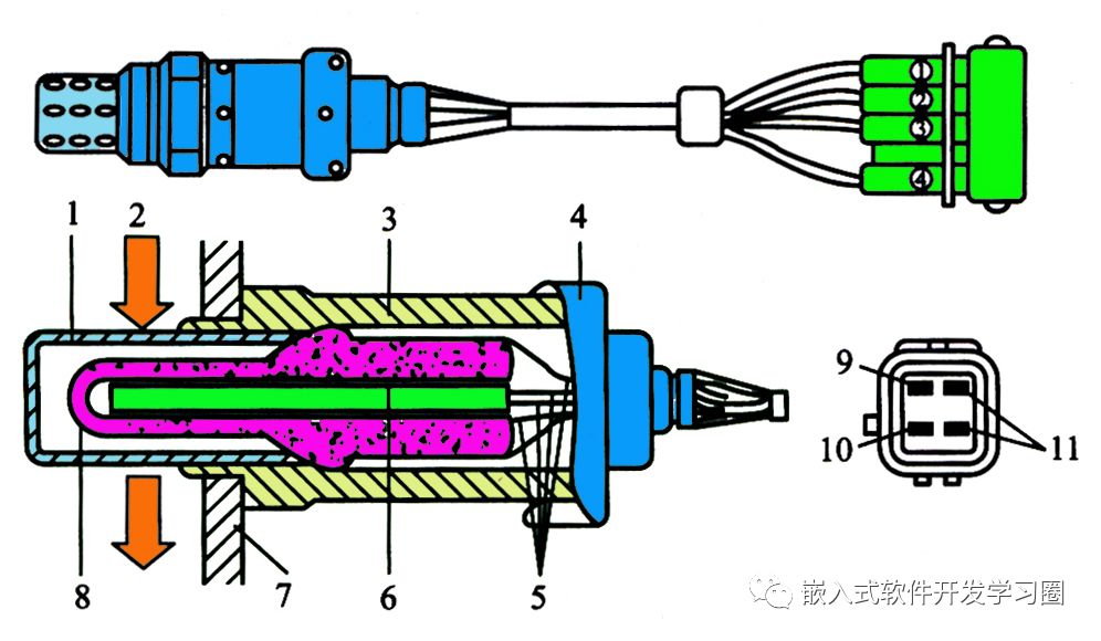
1—Steel protective tube 2—Exhaust 3—Housing 4—Waterproof sleeve 5—Electrode leads
6—Ceramic heating element 7—Exhaust pipe 8—Zirconia tube 9—Heating element power terminal 10—Heating element ground terminal 11—Signal output terminal
The zirconia tube’s ceramic body is porous, allowing oxygen molecules to ionize at high temperatures, turning into negatively charged oxygen ions that can diffuse and penetrate evenly through the solid zirconia electrolyte. When there is a concentration difference of oxygen between the inner and outer surfaces of the zirconia tube, oxygen ions from the high concentration side diffuse to the low concentration side to achieve equilibrium. When porous electrodes are placed on the surface of the solid electrolyte, an electromotive force E can be generated between the two electrodes. Because the inner side of the zirconia tube is connected to the atmosphere with high oxygen concentration, while the outer side is connected to exhaust with low oxygen concentration, and the oxygen content on the outer side varies with the concentration of the combustible mixture, the potential difference between the inner and outer surfaces of the zirconia tube changes with the concentration of the combustible mixture, effectively making the zirconia tube a concentration difference battery, and the signal source of the sensor is effectively a variable power source, as shown in the figure.
1—Exhaust 2—Exhaust pipe 3—Atmosphere 4—ZrO2 solid electrolyte 5—Platinum electrode
6—Alumina ceramic protective layer
The output characteristics of the zirconia oxygen sensor are as follows: when the combustible mixture supplied to the engine is rich (air-fuel ratio less than 14.7), the oxygen content in the exhaust is low, and the CO concentration is high. Under the catalytic action of platinum in the catalyst, nearly all oxygen reacts with CO to produce CO2 gas, resulting in an oxygen concentration of zero on the outer surface. Since the inner surface of the zirconia tube is connected to the atmosphere with a high oxygen concentration, and the outer surface is connected to exhaust with a low oxygen concentration, the concentration difference between the inner and outer surfaces of the zirconia tube is large, resulting in a high potential difference between the two platinum electrodes (approximately 0.9V).
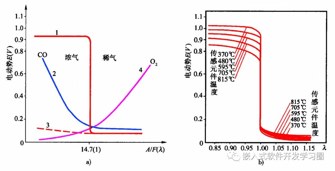
a) Relationship between gas concentration and voltage b) Relationship between sensor element temperature and voltage
1—Oxygen sensor electromotive force 2—CO concentration 3—Electromotive force without platinum electrodes 4—Oxygen concentration
When the combustible mixture supplied to the engine is lean (air-fuel ratio greater than 14.7), the oxygen content in the exhaust is high, and the CO concentration is low. Even if CO fully reacts with oxygen, there will still be excess oxygen on the outer surface. Therefore, the concentration difference between the inner and outer surfaces of the zirconia tube is small, resulting in a low potential difference between the two platinum electrodes (approximately 0.1V).
When the air-fuel ratio approaches the theoretical air-fuel ratio of 14.7, both the oxygen and CO content in the exhaust are low. Under the catalytic action of platinum, the chemical reaction between oxygen and CO changes sharply from an oxygen-deficient state (excess CO, oxygen concentration of zero) to an oxygen-rich state (zero CO, excess oxygen). Due to the rapid change in oxygen concentration difference, the potential difference between the platinum electrodes changes sharply, causing the sensor’s output voltage to change sharply from 0.9V to 0.1V.
(2) Titanium Dioxide Oxygen Sensor
Titanium dioxide (TiO2) is a high-resistance semiconductor at room temperature, but when it is oxygen-deficient, its lattice defects appear, causing its resistance to decrease. Additionally, its resistance is also temperature-dependent. The titanium dioxide oxygen sensor utilizes the characteristic of the resistance of titanium dioxide material changing with the oxygen content in the exhaust, thus also referred to as resistive oxygen sensors.
The limit current type oxygen sensor is an improved version of the zirconia concentration difference battery type oxygen sensor. When a certain voltage is applied across the ZrO2 component of the ZrO2 oxygen concentration difference battery type oxygen sensor, it causes the movement of oxygen ions, generating a current that is proportional to the oxygen concentration in the exhaust gas. The limit current type oxygen sensor utilizes this characteristic to continuously detect the air-fuel ratio in the lean combustion zone.
Electronic Control Unit (ECU)
The functions of the electronic control unit include the following aspects: providing reference (baseline) voltage (2V, 5V, 9V, 12V) to sensors; receiving information input from sensors or other devices, converting the input information into signals that can be accepted by the microcomputer; storing programs used for analysis and calculation, vehicle model characteristic parameters, data during calculations, and fault information; performing computations and analyses, determining execution commands based on information parameters, and outputting them to actuators; comparing the output information with standard values, identifying faults, and outputting fault information; and self-correction (adaptive function).
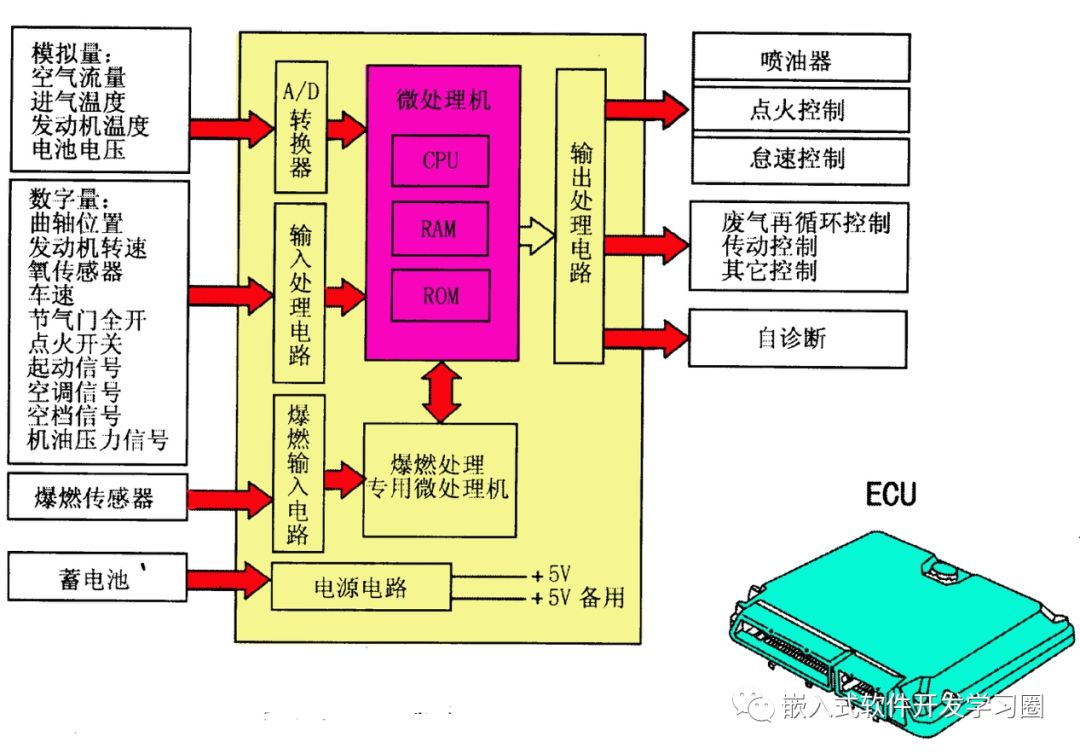
(1) Hardware of the Electronic Control Unit
The ECU mainly consists of input circuits, microcomputers, and output circuits.
(2) Software of the Electronic Control Unit
The software consists of control programs and data. The control software mostly adopts a modular structure, dividing the entire control system program into several relatively independent functional program modules, each designed, programmed, and debugged separately, and finally connecting the debugged program modules together. This structural approach facilitates program design and debugging, allows for easy modification, and enables selective adjustments as needed.
The main component of the software is the main control program. The main control program can set the content according to usage and control requirements. Its main tasks include initializing the entire system, implementing the working sequence of the system, setting control modes, and outputting injection and ignition signals under common operating conditions and other operating modes. The software also includes programs for processing speed and load, interrupt handling, look-up tables, and interpolation programs.
To achieve optimal control of the engine, matching tests should be conducted on engine test benches, emission test drums, and on-road testing to obtain three-dimensional graphs of basic fuel injection amounts and basic ignition advance angles, as well as other correction coefficients, correction functions, and constants determined for matching various operating conditions, all stored in discrete data form in memory to serve as the basis for control.
(3) Working Process
When the engine starts, the ECU enters the working state, and certain programs are retrieved from ROM into the CPU. These programs are used to control fuel injection, ignition timing, idle speed, etc. Under the control of the CPU, one instruction is executed in a loop.
Depending on the needs of the engine’s operating conditions, the ECU can operate in both open-loop and closed-loop control modes.
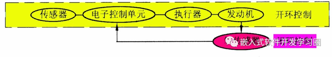
① Open-loop Control
During engine operation, the ECU controls the actuators based on the signals from the sensors, but the results of the control (such as whether the combustion is complete, whether the idle is stable, and whether knocking occurs) cannot be analyzed to determine whether the expected goals are achieved, and the control results do not affect the control process. This type of control is known as open-loop control. The characteristic of open-loop control is that there is only a forward control effect between the controller and the controlled object, with no feedback control effect.
② Closed-loop Control
The accuracy of open-loop control systems in adjusting the air-fuel ratio and ignition advance angle is limited by the engine’s technical condition and the control programs and data. Moreover, open-loop control systems cannot consider all other control parameters affecting the air-fuel ratio and ignition advance angle, making precise control difficult.
Closed-loop control is essentially feedback control. Based on open-loop control, the control system determines the increase or decrease of the output control amount based on the feedback signal from the actual detected results of the open-loop control. The characteristic of closed-loop control is that there is not only a forward effect between the controller and the controlled object but also a feedback effect, meaning the system’s output has a direct effect on the control amount.
Source: Embedded Software Development Learning Circle
Please scan the QR code to join the group