This article is a highlight from the Kanxue Forum.
Author from Kanxue ForumID: Hu Yimi
In this article, we plan to share about the Xiaotun AI camera, which is also the content we shared at a certain AIoT security summit in 2020. Last year, we received a batch of sponsorship, which included most of the devices from the Huawei IoT terminal reward program list, as shown in the figure below:
Figure 1-1 Huawei Terminal IoT Reward Program List
The Xiaotun AI camera is one of the items in the table, and among all the devices in the above image, the Xiaotun AI camera is relatively easier to analyze, making it suitable for sharing with everyone.
As usual, when we get a new device, we will definitely use it normally to see what functions the device provides and guess the operating logic behind it. By listening to the communication data during normal use, we can obtain the communication content between the phone and the camera as shown in the figure below:
Figure 2-1 Communication content between the camera and the phone
In the above figure, there is COAP protocol communication data between the phone and the camera. This part of the communication only occurs during the network configuration of the camera, after which the phone and the camera no longer communicate directly, but the communication data between the two is completely forwarded by the cloud, as shown in the figure below:
Figure 2-2 Communication content between the camera and the cloud
It can be seen that most of the communication between the camera and the cloud is TLS encrypted communication. In fact, the camera verifies the TLS certificate of the cloud, and we cannot obtain the communication content through simple man-in-the-middle attacks.
In addition to communication listening, we also scanned the TCP ports that the camera has opened, as shown in the screenshot below:
Figure 2-3 Nmap scan of the camera
The results show that the device does not listen on any TCP ports, which is quite troublesome.
In previous articles, we have analyzed a number of device firmware, so let’s get started smoothly. A simple review of the device’s official website confirms that the firmware is not available for download. Let’s directly open the device and take a look, as shown in the figure below:
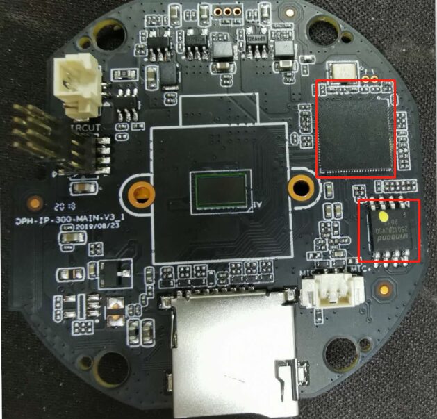
Figure 3-1 Camera circuit board
It can be seen that the device uses hi3518ev300 as the SoC, and a 16MB Flash memory with the model Winbond.
Those who have analyzed Huawei devices know that their official website does not disclose relevant information about HiSilicon chips, and only officially certified organizations can obtain the specified model chip manuals, and we are clearly not certified. However, the almighty Taobao helped us out; we were able to purchase the hi3518ev300 chip manual and development SDK on Taobao, which played an important role in the following text.
Figure 3-2 Purchasing complete information on Taobao
Using a hot air gun to blow the Flash memory off the board, we placed it in a programmer to extract the Flash content and submitted the extracted files to binwalk for analysis, and the results were quite satisfactory; everything that needed to be analyzed was analyzed, as shown in the figure below:
Figure 3-3 Binwalk analysis results
In the IoT reward program list, devices like routers and AI speakers cannot be directly analyzed using binwalk; we will share the analysis process of those devices with everyone when we have the opportunity.
Through the binwalk analysis results, we can confirm that the camera runs an embedded Linux operating system. Therefore, the next task is to log into the system in some way to observe the running state of the programs in the system and debug the code of interest.
Although QEMU can also be used for debugging, analyzing and debugging directly on the original device is definitely a better choice. To log into the system, we encountered many pitfalls; we won’t repeat the process of stepping into those pitfalls in this article. Interested readers can look for the PPT shared at that conference. Here we directly provide the three login methods we used: serial login, telnet login, and reverse shell login.
With the chip manual purchased from Taobao and a multimeter, we can determine that the several vias on the circuit board are the UART interface of the SoC, as shown in the figure below:
Figure 4-1 Circuit board UART interface
Simply connecting the UART interface on the circuit board is not enough to use the UART serial port normally. To enable the camera’s serial port, two steps are required: first, adjust the boot parameters (bootargs) used by uboot when booting the Linux kernel; second, adjust the various settings for the serial port in the Linux startup script.
Open the uboot section in the firmware with a hex editor, observe this part of the firmware content, and compare it with the uboot firmware structure described in the SDK documentation, as shown in the figure below:
 Figure 4-2 Camera firmware structure
By comparing the two images in Figure 4-2, we can determine that the first four bytes are the magic word, indicating that the device has started the secure boot mechanism. Under the protection of this mechanism, the boot ROM code will perform an RSA signature check on the uboot section to prevent the uboot program from being tampered with. The next four bytes represent the total length of the uboot section, which is 0x036A58 bytes in this device.
Since the entire uboot section is protected by RSA signature verification, and we do not have the signing private key to recalculate the signature, this part of uboot cannot be modified. However, through in-depth reverse analysis of the uboot code, we found that uboot does not perform signature verification on other parts of the firmware, which means we can adjust the file system at will. In addition, we found that the boot parameters for the Linux kernel are stored outside of uboot, as shown in the figure below:
Figure 4-3 Linux boot parameters of the camera
In the above figure, the location of the kernel boot parameters is 0x40000, which exceeds the range of uboot. Therefore, we can adjust the boot parameters, as shown in the figure below:
Figure 4-4 Adjusted Linux boot parameters
In the above figure, the first four bytes are the crc32 checksum. Since we changed the boot parameters, we need to recalculate the crc32 value and fill it back here.
Next, we will check the startup scripts in the squashfs file system (big_run.sh and small_run.sh) and compare them with the content of the chip manual in the SDK documentation, as shown in the figure below:
Figure 4-2 Camera firmware structure
By comparing the two images in Figure 4-2, we can determine that the first four bytes are the magic word, indicating that the device has started the secure boot mechanism. Under the protection of this mechanism, the boot ROM code will perform an RSA signature check on the uboot section to prevent the uboot program from being tampered with. The next four bytes represent the total length of the uboot section, which is 0x036A58 bytes in this device.
Since the entire uboot section is protected by RSA signature verification, and we do not have the signing private key to recalculate the signature, this part of uboot cannot be modified. However, through in-depth reverse analysis of the uboot code, we found that uboot does not perform signature verification on other parts of the firmware, which means we can adjust the file system at will. In addition, we found that the boot parameters for the Linux kernel are stored outside of uboot, as shown in the figure below:
Figure 4-3 Linux boot parameters of the camera
In the above figure, the location of the kernel boot parameters is 0x40000, which exceeds the range of uboot. Therefore, we can adjust the boot parameters, as shown in the figure below:
Figure 4-4 Adjusted Linux boot parameters
In the above figure, the first four bytes are the crc32 checksum. Since we changed the boot parameters, we need to recalculate the crc32 value and fill it back here.
Next, we will check the startup scripts in the squashfs file system (big_run.sh and small_run.sh) and compare them with the content of the chip manual in the SDK documentation, as shown in the figure below:

Figure 4-5 Settings for the pins in the startup script
It can be seen that in the startup script, this pin of the SoC is set to GPIO function. We need to adjust the startup script to reset this pin to UART function, as shown in the figure below:
Figure 4-6 Adjusted startup script
After completing the above two adjustments, we need to repackage the firmware and burn it to Flash. Since the Linux startup script is in the squashfs file system extracted by binwalk, we need to use the mksquashfs tool in the SDK to repackage the squashfs file system. The specific method has been introduced in previous articles on the analysis of Hikvision devices, so I won’t elaborate further here.
After completing the above work, we can power on the device again to use serial login, as shown in the figure below:
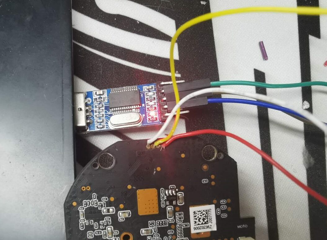

Figure 4-7 Successfully logged into the device via serial port
Although serial login is possible for the camera device, it still requires hardware circuit connections, which can be cumbersome. If we could log in via telnet, it would be more convenient. Starting the camera’s telnetd also requires two steps: first, recompile busybox to add telnetd functionality; second, mount the device file in the Linux startup script.
Before starting, we need to configure the SDK development environment properly, such as the cross-compiler, etc. Fortunately, the SDK we purchased is quite good; it has all the necessary documentation and scripts, so we can proceed step by step according to the instructions. In the development documentation, we can find the section related to configuring the SDK, as shown in the figure below:
Figure 5-1 Configuring the SDK development environment
Following the SDK installation method in the above image, we step by step complete the installation of the SDK. During the installation process, some files may need to be downloaded; don’t worry, under a normal network environment, everything can be downloaded smoothly without additional auxiliary tools.
Next, in the squashfs file system extracted by binwalk, we can find a symlink to telnetd, which links to the busybox program. After reverse analyzing the busybox program, we can find that the busybox program in the firmware does not implement the telnetd function, as shown in the figure below:
Figure 5-2 List of commands supported by busybox
In the above figure, the busybox command list does not include telnetd. To solve this problem, we need to recompile the busybox program in the SDK. We have already completed the SDK deployment work for the development environment.
The SDK contains the code and related makefile files needed to compile busybox. We just need to adjust the .config file to ensure that the compiled busybox program includes telnetd, tftpd, and other required functions, and then execute make hibusybox, as shown in the figure below:
Figure 5-3 .config file when compiling busybox
After compilation, replace the original busybox program in the firmware file system with the compiled busybox to ensure that the camera has the telnetd functionality. Next, we also need to mount the devpts device file; otherwise, telnetd will crash after establishing the first telnet connection.
Place the two commands to mount the devpts device file in the Linux startup script (big_run.sh and small_run.sh) and add the command to start telnetd, completing all adjustments to the file system, as shown in the figure below:
Figure 5-4 Adjusted Linux startup script
Finally, repackage the file system and burn it to Flash. After powering on again, you can log into the camera device via telnet.
6. Reverse Shell Analysis
Although the two methods mentioned above have successfully logged into the Linux operating system, the Flash has already been blown off, so we prepare a simple reverse shell as a backup measure to avoid having to blow and solder the Flash repeatedly if the first two methods fail.
In this section, we prepared a simple reverse shell code as a backup measure. There are many reverse shell codes; we can choose any one. The following code snippet is the reverse shell code we will compile:
Figure 6-1 Reverse shell program
The code is quite simple; after establishing a TCP connection, it redirects input and output to the TCP connection.
Compile this program using the cross-compiler included in the SDK, then test it locally with QEMU. After successful testing, place it in the firmware’s file system, and add the command to start the reverse shell in the Linux startup script. Finally, package the file system and burn the firmware to Flash. After the camera starts normally, use nc on the host to listen to the set port, and you can log into the device’s Linux system through the reverse shell, as shown in the figure below:
Figure 6-2 Logging in through reverse shell
7. Hilink Program Analysis
After successfully logging into the device’s Linux system, we begin analyzing and debugging the programs running on the device. Among the three login methods mentioned earlier, telnet is the simplest and easiest to use, so we will uniformly use telnet as the login method in the following text.
First, use the ps command to view the key processes running in the system, as shown in the figure below:
Figure 7-1 Programs running in the camera device
In the above figure, there are three key processes: hilink is responsible for key modules, ipc is responsible for the main logical functions of the camera, and monitor seems to be responsible for monitoring the device’s operating status. In the previous article, we mentioned that the TLS communication between the camera and the cloud is generated by the hilink program, so let’s analyze the hilink program.
As usual, we first enable the running logs of this program. By reverse analyzing this program, we can find the function used to determine whether to print logs, as shown in the figure below:
Figure 7-2 Determining whether to print logs
In the above figure, the logLevel function is used to determine whether the current log level (R0=3) logs need to be printed. We just need to modify the logLevel function’s return value to always be 1 to print all logs.
By running the logs, we can roughly grasp the program’s execution flow. After the program starts, it will first register and log in to the cloud, using the key string “LoginToCloud” to find the key code segment, as shown in the figure below:
Figure 7-3 hilink logging into the cloud
Based on the content in the above figure, it is inferred that the communication content involves not only TLS encryption but also application layer encryption. At this point, static analysis alone is a bit difficult; let’s compile a gdbserver and transfer it to the device for debugging. The SDK includes the gdb project, and as long as we compile it normally, we can use it directly.
Our compiled busybox includes tftp functionality, which can be used to transfer files. For content related to gdbserver debugging, please refer to the analysis article on Hikvision’s Yingzi; we will not elaborate here. The debugging screenshot is as follows:

Figure 7-4 Debugging the hilink program
Through debugging, it can be confirmed that a large part of the requests do not execute the hilink_encrypt_coap_buf function, which means that application layer encryption is not performed.
Next, let’s try to patch the program, fix its TLS certificate, and perform a man-in-the-middle attack to see if we can obtain the communication data. The script used for patching is as follows:
Figure 7-5 Patching the hilink program
This script is also quite simple; it only changes the TLS certificate in the program to a TLS certificate we generated ourselves.
Finally, let’s write a script to implement a man-in-the-middle attack, and simply organize the communication content, we can obtain the content shown in the figure below:
Figure 7-6 Obtaining hilink program communication content
The communication content in the above figure can help us continue to analyze deeply, but we won’t elaborate too much here; interested readers can try it themselves.
The analysis article on the Xiaotun AI camera ends here. In this analysis, we introduced three common ways to log into the Linux operating system: serial, telnet, and reverse shell. Readers can choose one of these methods based on the actual situation when analyzing other devices.
In addition, through the various attempts made in this article on this camera, the device is already in a debuggable state. In this article, we only conducted a preliminary analysis of the hilink program running in the camera. Interested readers can continue to explore and uncover potential vulnerabilities based on this.
Finally, I hope this article can bring some gains to the readers. If you have anything you want to discuss or talk about, feel free to contact us via WeChat: PwnMonkey. In future articles, we will continue to share other research cases, so stay tuned.

Kanxue ID: Hu Yimi
https://bbs.pediy.com/user-home-613694.htm
*This article is original by Kanxue Forum Hu Yimi, please indicate that it is from the Kanxue community when reprinting.
# Previous Recommendations
-
AUPK: De-sheller based on Art virtual machine
-
Symbolic execution Symcc and fuzz testing AFL combined practice
-
x64dbg usage skills and practical plugin collection
-
Simple analysis of malicious samples
-
Reverse analysis of message record database file decryption of a certain chat tool
Public Account ID: ikanxue
Official Weibo: Kanxue Security
Click “Read the original text” to learn more!