Section 1: Common Tools for Electricians
1. Common Tools for Electricians
1. Pliers
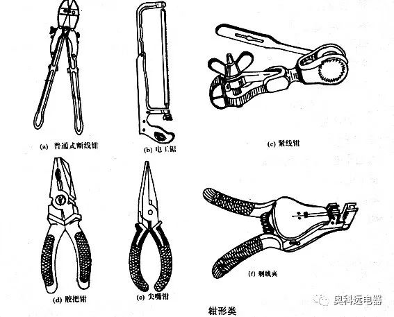
The pliers category includes wire cutters, rubber-handled pliers, needle-nose pliers, tensioning pliers, and wire strippers (as shown in Figure 6-1). Wire cutters are used to cut cold-rolled steel wire. Tensioning pliers are used to tighten lines during the installation of overhead lines and guy wires. Wire strippers are used to remove insulation from joints during wiring installations.
2. Climbing Equipment
Climbing tools include safety hooks, A-frame ladders, climbing boards, and high-safety belts.
3. Electrical Tools
Electrical tools include electric drills, soldering irons, 10kV insulated clamp meters, and insulated rods for opening (closing) circuit breakers. Insulated clamps are mainly used in power systems of 35kV and below for installing or removing high-voltage protection or performing similar tasks. Insulated rods, also known as operating rods or pull rods, are primarily used to operate high-voltage isolating switches below 35kV, drop-out fuses, install and remove temporary grounding wires, and conduct measurement tests.
2. Use of Blowtorches and Voltage Testers
1. Blowtorch
A blowtorch is used in the field for welding cable joints or melting the outer insulation of cable joints. When using a blowtorch, special attention should be paid to fire safety; the blowtorch should be kept away from flammable and explosive materials; check for oil or gas leaks before use; no one should be in front when igniting the blowtorch; the blowtorch should not be placed near heating objects; the fuel should not exceed two-thirds of the tank; pressure adjustments should be appropriate; refueling and repairs should be done after extinguishing the flame; the safe distance of the blowtorch flame from live parts should be no less than 1.5m for voltages below 10kV and no less than 3m for voltages above 10kV; the blowtorch should not be used for extended periods; when not in use, the flame should be extinguished and pressure released, and it should only be stored in the toolbox after completely cooling down.
2. Use of Voltage Testers
Voltage testers, also known as voltage detection pens, are used to check whether electrical equipment or circuits are live. When testing for voltage, the hand should touch the metal part at the end of the pen, and the tip should contact the metal part of the wire or the socket or conductor connected to it. When the neon tube in the voltage tester lights up, it indicates that the device or wire being tested is live. If the tester is held incorrectly, as shown in the diagram, the neon tube will not light up, leading to incorrect conclusions about whether the device or wire is live.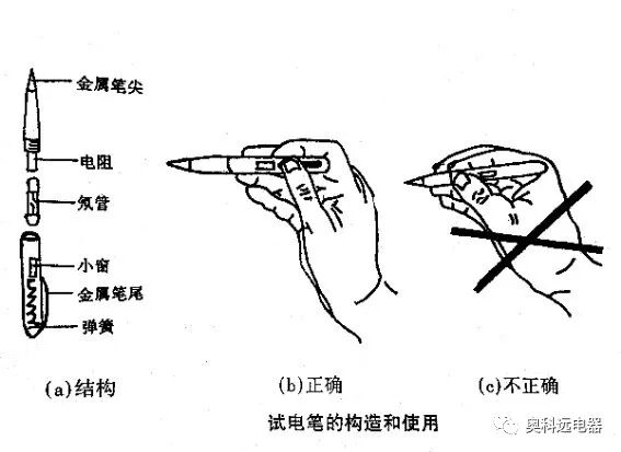
Section 2: Overview of Electrical Instruments
1. Types of Electrical Instruments
① By reading method: direct reading instruments and comparative instruments.
② By working principle: electromagnetic, electrodynamic, magnetic-electric, inductive, rectifying, thermoelectric, electronic, electrostatic, etc.
③ By measured quantity: voltmeters, ammeters, wattmeters, ohmmeters, energy meters, frequency meters, and multimeters.
④ By usage: panel-mounted and portable.
⑤ By the nature of the measured quantity: DC instruments, AC instruments, and dual-purpose instruments for AC and DC.
2. Electrical Measurement Errors
① Systematic error: also known as regular error, which remains constant or varies according to a pattern when repeatedly measuring the same quantity.
② Random error: in measurements, if the factors causing systematic errors have been eliminated, errors caused by poor contact, occasional overheating of resistive components, and various transient disturbances are called random errors.
③ Gross error: also known as blunder error, refers to values with obvious mistakes, generally caused by the experimenter’s inattention, using faulty measuring equipment, or errors in reading values. This type of error is completely avoidable.
3. Range
The maximum value that an instrument can measure is called the range (or measurement upper limit).
4. Accuracy
Accuracy (or precision) is reflected by errors. We first introduce absolute error, relative error, and reference error.
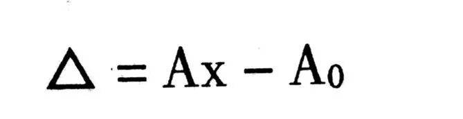
① Absolute error △ is the difference between the value measured by the instrument Ax and the actual value Ao.
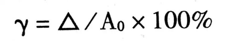
② Relative error y is the ratio of absolute error △ to the actual value Ao.
Since the value of Ao is difficult to determine, Ax can be used as an approximation to calculate Yo.
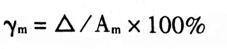
③ Reference error Ym is the ratio of absolute error △ to the measurement upper limit A. Reference error is also called accuracy.
The larger (or smaller) the value of Y, the lower (or higher) the accuracy, and the larger (or smaller) the error.
④ The accuracy of direct reading instruments is divided into seven levels: 0.1, 0.2, 0.5, 1.0, 1.5, 2.5, 5.0, with corresponding reference errors of ±0.1%, ±0.2%, … up to ±5.0%. Typically, 0.1 and 0.2 level instruments are used as standard meters, while 0.5 to 1.5 level instruments are used in laboratories, and the accuracy level for engineering instruments is between 1.5 and 5.0.
5. Sensitivity
Sensitivity (S) refers to the minimum value that an instrument can measure while ensuring accuracy. When the value of S is large (or small), we say the sensitivity is low (or high).
6. Reliability
Reliability reflects the production quality of the instrument; good reliability means fewer faults and easier repairs.
7. Insulation Resistance, Voltage Resistance, Overload Capacity
Insulation resistance refers to the resistance between all circuits in the instrument and its shell. Voltage resistance refers to the voltage value that this insulation resistance can withstand. Overload capacity refers to the voltage and current values that the instrument can withstand for a short time beyond its range. To ensure safe use, instruments must have sufficient insulation resistance, voltage resistance, and overload capacity.
Additionally, instruments should also have mechanical strength, anti-interference (such as electromagnetic interference) capability, adaptability to harsh environments (such as high temperature and high humidity), and ease of use. The meanings of these indicators are clear, so they will not be elaborated on.
Section 3: Electrical Instruments
1. Ammeters
The method for measuring current is to connect the ammeter in series with the circuit being measured; the lower the internal resistance of the ammeter, the less it affects the circuit being measured.
1. Direct Measurement Ammeters
The magnetic-electric measurement mechanism can directly measure DC currents below several tens of milliamps, while the electromagnetic mechanism can directly measure AC and DC currents up to 200A, and the electrodynamic mechanism can directly measure AC and DC currents below 0.5A. Ammeters composed solely of these measurement mechanisms are called direct measurement ammeters.
2. Ammeters Using Shunts
Some instruments have too small a range; to expand the range, shunts are used. A shunt is essentially a resistor with a very low resistance, as shown in the diagram, where IX is the measured current, In is the shunt current, A is the ammeter, Rn is the shunt, and IA is the ammeter current.
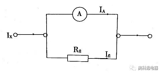
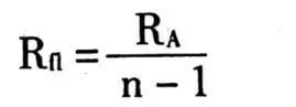
The relationship between IX and IA and the calculation formula for Rn will be derived below.
Let the internal resistance of the ammeter be RA, then
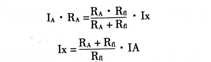
From the above formula, multiplying the indicated value of the ammeter IA by the coefficient (RA + Rn)/Rn gives the measured current IX. If the scale of the ammeter is made according to formula 6-4, IX can be read directly.
Let the shunt expand the range of the ammeter by n times, then
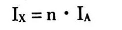
Substituting into the above formula gives the calculation formula for Rn.
The total internal resistance of the ammeter equals the parallel value of RA and Rn; the smaller Rn is, the less it affects the working state of the circuit being measured. However, as can be seen from the above formula, its value is limited by RA.
In practice, the value is limited by the sensitivity of the meter; practical shunts are not marked with resistance values but with rated current and voltage values (uniformly specified as 75mV or 45mV) for convenience. For example, a shunt rated for 100A and 75mV means that this shunt should be used with an ammeter head with a voltage range of 75mV (the voltage range of the ammeter head equals its current range multiplied by its internal resistance R); at this time, the range of the ammeter is 100A.
3. Ammeters Using Current Transformers
The shunt mentioned above can expand the range but has two drawbacks: one is that it consumes a lot of power, and the other is that it cannot isolate the measuring instrument from the circuit being measured, which is unsafe. To overcome these drawbacks, current transformers are used in AC current measurements to expand the range, as shown in the diagram, but transformers cannot be used in DC circuits, so they cannot replace shunts.
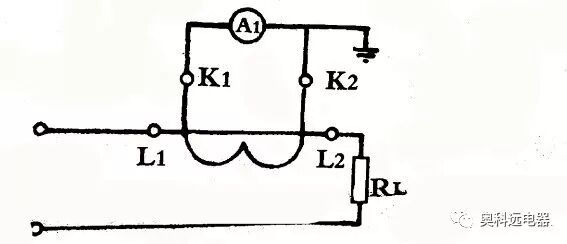
Aammeter head,L1L2primary coil,K1K2secondary coil,RLload resistance
▲ Ammeter with Current Transformer
The transformer is essentially a transformer with an iron core, utilizing the transformer’s voltage and current transformation characteristics, generally converting high voltage to low voltage and large current to small current for measurement, thus expanding the range of the meter. Commonly used transformers have accuracy levels of 0.5, 1.0, and 3.0.
4. Multi-range Ammeters
If a 1A ammeter is used to measure currents of several tens of milliamps, the pointer’s swing will be small, leading to significant measurement errors. To improve measurement accuracy, the pointer’s swing should exceed half of the full scale. Therefore, multi-range ammeters have been designed.
5. Clamp Meters
Clamp meters are primarily used to measure the current in live electrical lines. Common clamp meters include T301, T302, and MG series.
① Usage:
Clamp the live wire to be measured within the jaws of the clamp meter, then read the current value from the meter’s display, as shown in the diagram.
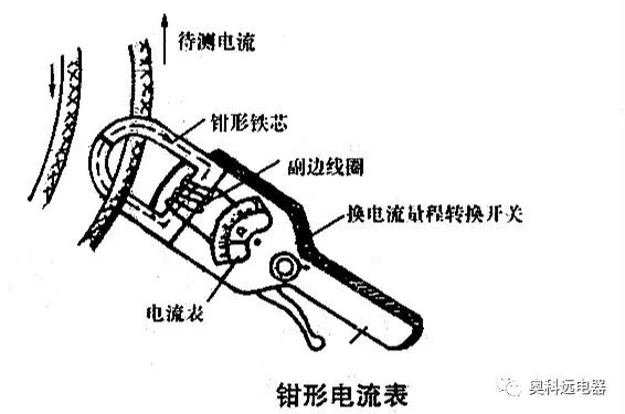
When measuring current, ensure that the voltage on the circuit is below the rated value of the meter, and immediately switch back to the zero range after measurement. When measuring small currents, if the current reading is below half of the meter’s minimum range, it may be difficult to read accurately; in this case, wrap the wire being measured around the jaws a few times, read the current value, and then divide the reading by the number of turns to obtain the actual current in the wire.
② What precautions should be taken when using clamp meters?
Since clamp meters are used to measure live electrical equipment, care must be taken when using handheld clamp meters on live lines; do not measure uninsulated wires. If there is vibration or noise when the wire is clamped, rotate the handle of the meter a few times or open and close it again until there is no noise before reading the current value. During the first measurement, it is advisable to use the maximum current range for estimation, then switch to the appropriate range for formal measurement. Each time the range is changed, the jaws must be opened before switching the range switch. The jaws of the clamp meter must be kept clean and dry.
2. Voltmeters
Voltmeters
The method for measuring voltage is to connect the voltmeter across the two points being measured in parallel. Unlike ammeters, the higher the internal resistance of the voltmeter, the less it affects the circuit being measured.
Ammeters can also be used to measure voltage directly, as long as the voltage scale is calibrated according to the product of the current and the internal resistance of the meter head. Clearly, this method has a very small range (equal to the rated voltage U of the meter head) and is not very useful in engineering. To expand the range, voltage divider resistors R are used, as shown in Figure 6-7. For now, ignore the voltage transformer HY, let the measured voltage UX be directly applied to the meter head (the voltmeter is formed together with V and Rfy), most of UX drops across Rfy.
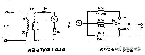
Next, we will discuss the relationship between UX and the voltage at the meter head UV, as well as the calculation formula for Rfy. According to the voltage divider formula (assuming the internal resistance of the meter head is RV), we can obtain:
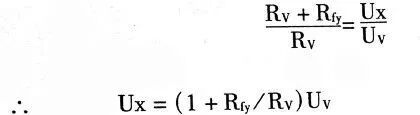
From the above formula, multiplying the indicated voltage UV by the coefficient (1 + Rfy + RV) gives the value of the measured voltage. By calibrating the scale of the meter head according to the above formula, the value can be read directly.
If the rated voltage of the voltmeter head is to be expanded by m times, then
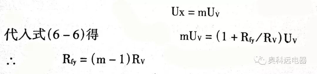
This is the calculation formula for the voltage divider resistor Rfy.
The total internal resistance of the voltmeter R = Rfy + RW, mainly depends on Rfy. The larger Rfy is, the smaller the current drawn from the circuit being measured, and the less it affects the working state of the circuit. However, the value of Rfy is limited by RV, which is fundamentally limited by the sensitivity of the meter head.
To isolate the voltmeter from the circuit being measured for safety, voltage transformers are used in AC voltage measurements.
A voltage transformer is equivalent to a step-down transformer. Its primary coil has different rated voltage levels, while the secondary output voltage is designed to be 100V. This way, different specifications of transformers can use the same range of measuring meter heads (of course, the scale of the meter head must correspond to the primary voltage).
Similar to the design of multi-range ammeters, multi-range voltmeters have also been designed, with the principle shown in the diagram of the multi-range voltmeter.
3. Ohmmeters
Basic Principle of Ohmmeters
Ohmmeters are used to measure resistance values. Resistance values cannot be measured directly and need to be converted into current signals for measurement, as shown in the diagram.
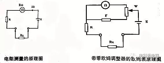
Rx is converted into a current signal In through the measuring circuit, and Rx changes In also changes. Ih is a function of Rx, and IΩ can represent the size of Rx. (The measuring circuit consists of E, R, and Rn, which integrates with the meter head.) By measuring the value of IΩ, substituting the value of In into the relationship between Rx and IΩ allows us to obtain the value of Rx. The relationship between Rx and In is as follows:
The meter head of the ohmmeter is used to measure In; it is essentially a current meter head, but its scale is calibrated according to the above formula in ohm values, allowing Rx to be read directly from the meter head.
The characteristics of ohmmeters are that they require a power source E to perform measurements, the scale is inverted (i.e., as Rx increases, IΩ decreases, and the pointer’s swing amplitude decreases), and the scale is non-uniform (the relationship between Rx and In is not proportional). Another characteristic is the need for a zero-ohm adjuster.
Since E cannot remain constant (for example, the voltage of dry batteries changes over time), when Rx = 0, the pointer cannot remain at zero, leading to measurement errors. To solve this problem, ohmmeters are equipped with zero-ohm adjusters, as shown in the diagram. It can be seen that by adjusting the potentiometer W, I1 can be finely adjusted to achieve zero adjustment.
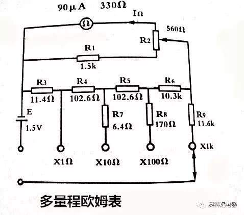
Multi-range ohmmeters are shown in the diagram. It can be seen that the expansion of the range is achieved by increasing the circuit sensitivity (reducing the shunting of In). If the range needs to be further expanded (for example, to R × 10k, R × 100k), it is generally achieved by increasing the power supply voltage.
4. Megohmmeters
1. Structure of Megohmmeters
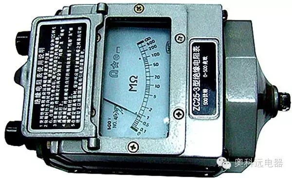
Megohmmeters are used to measure large resistances (mainly insulation resistance). The unit of measurement is megohms (M), and the commonly used accuracy levels for megohmmeters are 1.0 or 1.5.
Megohmmeters mainly consist of a hand-cranked generator and a magnetic-electric ratio meter. The magnetic-electric ratio meter is a special form of magnetic-electric mechanism. It has two moving coils that intersect, with the pointer fixed on the same axis, without a restoring torque spring. Since there is no restoring torque spring, the pointer of the meter may stop at any position when the meter is not working.
2. Usage
(1) Selection of Megohmmeters
The rated voltage of the selected megohmmeter must correspond to the working voltage of the electrical equipment or circuit being tested, as shown in Table 6-1.
If measuring the insulation resistance of high-voltage equipment with a megohmmeter rated below 500V, the measurement results will not accurately reflect the insulation resistance under working voltage. Similarly, a megohmmeter with too high a voltage rating should not be used to measure the insulation resistance of low-voltage equipment to prevent damage during measurement. The appearance of a megohmmeter is shown in Figure 6-12.
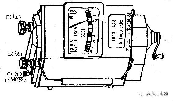
▲ Megohmmeter
(2) Use of Megohmmeter Connection Terminals
The megohmmeter has three connection terminals: “Line” (L), “Ground” (E), and “Shield” (G). For general measurements, the insulation resistance to be measured should be connected between L and E. For measuring objects that are not clean or are damp, to accurately measure the internal insulation resistance of the insulating material (i.e., volume resistance), the G terminal must be used.
(3) Precautions for Measuring Insulation Resistance
1. Measurements with a megohmmeter must be performed with the power off, and energy-storing components should be discharged in advance.
2. The handle should not be cranked too forcefully; it should be turned clockwise, gradually increasing to maintain a uniform speed of about 120 revolutions per minute.
3. Before measurement, a short-circuit test should be performed on the megohmmeter to verify its integrity; the time for the pointer to return to zero should be minimized.
4. Test leads should not be made of twisted pair wire.
5. During measurement, the handle should be cranked first, then the test should be performed; after testing, the test leads should be disconnected before stopping the cranking.
6. During measurement, both hands should not touch the two test leads simultaneously.
The connection method for measuring the insulation resistance of cable lines is shown in the diagram.
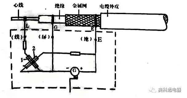
▲ Connection for Measuring Cable Insulation Resistance
|
Selection of Megohmmeters |
||
|
Measured Object |
Rated Voltage of Measured Equipment (V) |
Rated Voltage of Megohmmeter (V) |
|
Coil Insulation Resistance |
Below 500 |
5000 |
|
Above 500 |
1000 |
|
|
Insulation Resistance of Power Transformer Coil and Motor Coil |
Above 500 |
1000~2500 |
|
Insulation Resistance of Generator Coil |
Above 500 |
1000 |
|
Insulation Resistance of Electrical Equipment |
Below 500 |
500~2500 |
|
Above 500 |
2500 |
|
|
Porcelain Insulators |
2500~5000 |
5. Ground Resistance Measurement Instruments
Usage of Ground Resistance Measurement Instruments
When electrical equipment is in operation, to prevent insulation breakdown or leakage that could electrify the outer casing and cause personal accidents, the equipment casing must be grounded. To prevent lightning strikes, lightning rods and wires on tall buildings or high-voltage transmission lines must also be reliably grounded. After installing the grounding wire, the ground resistance must be measured. Ground resistance is typically measured using ground resistance measurement instruments, as shown in the connection method for the ZC-8 ground resistance measurement instrument. After short-circuiting P2 and C2, E is the terminal connected to the ground electrode being measured, P1 is the potential auxiliary probe, and C1 is the current auxiliary probe. The range switch is divided into three ranges: 0-10, 0-100, and 0-1000. The ground resistance to be measured is connected between E and P.
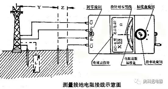
1. Connect the Ground Electrode and Probes
First, insert the potential auxiliary probe P and the current auxiliary probe C1 approximately 20m away from the ground electrode, keeping a certain distance between the two probes, then connect them to the P and C1 terminals with wires, and connect the ground electrode to E.
2. Zero Adjustment of the Galvanometer
Use a screwdriver to adjust the knob in the diagram so that the pointer of the galvanometer aligns with the zero line, thus calibrating the galvanometer to zero.
3. Select the Range and Adjust the Scale
After zeroing the galvanometer, set the range switch to the x10 position, with the resistance range being 0-100Ω. Gradually increase the speed of the generator to reach about 120 revolutions per minute, and adjust the scale to make the galvanometer pointer point to zero.
Ground Resistance Value = Multiplier × Scale Reading
4. Others
If using the ZX-8 ground resistance measurement instrument to measure general resistance, P and C can be short-circuited as E, and the resistance to be measured is connected between E and R (i.e., C), with the measurement steps being the same as before.
6. Multimeters
Multimeters are commonly used multifunctional and multi-range electrical instruments in electrical engineering. Generally, multimeters can measure DC voltage, current, AC voltage, and resistance. They consist of a meter head, measuring circuit, and range switch. The switch should be turned to the required measurement range.
① The multimeter must be placed flat and stable during use.
② Adjust the zero point before use; if the pointer is not at zero, turn the zero adjustment knob to make the pointer point to “0”.
③ Select the range before use; ensure the range switch is set correctly for each measurement category (DC, AC, voltage, current, resistance), and never blindly test without checking the probe connections.
④ When measuring voltage or current, if the quantity to be measured is unknown, use the maximum range for initial testing; if the pointer deflection is too small, switch to the appropriate range for measurement.
⑤ When measuring resistance, first turn the range switch to the resistance position (Ω), short the two probes, and then rotate the zero adjustment to make the pointer point to zero ohms.
⑥ When measuring DC voltage or current, pay attention to the probe polarity: the red probe is “+” and the black probe is “-”. Ensure the probes are inserted into the correct terminals and that the connections to the circuit being measured are correct. If unsure, a quick test can be performed by selecting a large range and quickly connecting the probes to the circuit; if the pointer moves in the positive direction, the connections are correct; otherwise, switch the probe polarity.
⑦ When measuring voltages between 500 and 2500 volts, especially ensure the range switch is set to 2500 volts; first connect the ground probe to the negative terminal, then connect the other probe to the high-voltage measurement point, ensuring that the probes, fingers, and surroundings are dry and taking insulation measures for safety.
⑧ When reading measurements, carefully observe the scale line for the selected range, especially when measuring small voltages below 10 volts.
⑨ Do not change the range switch while the circuit is live.
⑩ Try to train one hand to operate the measurement while the other hand does not touch the object being measured.
⑪ After each measurement, return the range switch to the maximum AC voltage range.
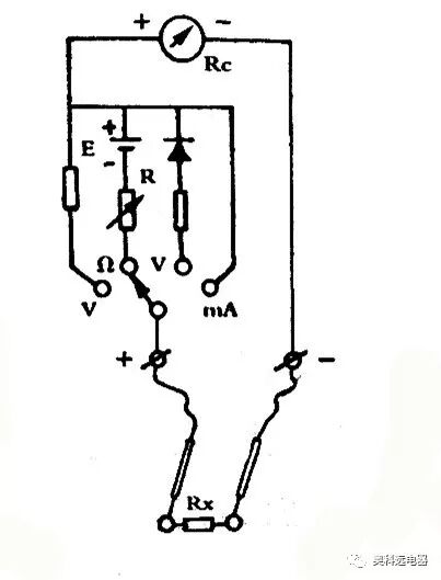
▲ Simple Multimeter Circuit Diagram
Section 4: Safety in Using Electrical Instruments
1. Safe Use of Ammeters
1. Safe Use of Ammeters
Prevent the misuse of ammeters to measure voltage; otherwise, excessive current may flow through the meter head (the internal resistance of ammeters is generally very low), damaging the meter head.
The iron core and secondary of current transformers must be grounded to prevent insulation damage and high voltage from entering the secondary circuit.
The secondary of current transformers must never be open-circuited. If the secondary suddenly opens, the magnetic flux in the core will greatly increase (potentially increasing by dozens of times). This will significantly increase core losses and cause a rapid rise in temperature, while the secondary coil may induce high voltage (up to hundreds of times the normal value), damaging the current transformer and posing a risk to personal safety. No switches or fuses should be installed in the secondary circuit to avoid opening the circuit when the switch or fuse fails. When removing the secondary instrument, the secondary must first be short-circuited (some current transformers come with short-circuit switches).
Clamp meters must not change ranges during use, as this could cause an open circuit in the secondary of the current transformer.
For multi-range meters, the correct range must be selected; when measuring DC currents, the polarity must be clear to prevent errors due to incorrect polarity. The same applies to voltmeters, ohmmeters, etc. If the polarity is unclear, quickly connect and disconnect the probes to observe the direction of the pointer’s swing to determine the polarity.
2. Safe Use of Voltmeters
When measuring high voltages, wear insulated gloves, use only one hand to hold the probes, and ensure good insulation between the body and the ground, with a supervisor present. The iron core and outer casing of the secondary coil of voltage transformers must be reliably grounded to prevent high voltage from entering the secondary circuit in case of insulation failure.
The secondary of voltage transformers must not be short-circuited; otherwise, the transformer may be damaged. To prevent short-circuit accidents, fuses should be installed on both the primary and secondary sides.
3. Safe Use of Ohmmeters
Prevent the misuse of ohmmeters to measure voltage. If the internal resistance of the meter is low and the voltage across the resistance is high, it may damage the instrument.
When measuring the insulation resistance of equipment, the power must be turned off, and the equipment must be grounded and discharged (some equipment has large capacitance, such as capacitors, transformers, motors, and cable lines) to ensure personal safety and accurate measurement results. Measurements should not be taken if the induced voltage of the object exceeds 12V. Measurements should not be taken on overhead lines and associated electrical equipment during thunderstorms.
To prevent electric shock, do not touch the object being measured while the megohmmeter is in operation (the generator is running). After testing, the object must be discharged to ground before allowing contact. For objects with large capacitance, discharge to ground first, then stop cranking the generator to prevent capacitor discharge from damaging the megohmmeter.
4. Safe Use of Multimeters
The safety content discussed for ammeters, voltmeters, and ohmmeters largely applies to multimeters as well. Here are a few additional points. First, before measurement, check that the function and range settings are correct to prevent using the resistance or current range to measure voltage or using a small range to measure large signals, which is easily overlooked, especially in busy situations. Second, when not in use, the range switch should be set to the highest voltage range to prevent damage if someone uses it blindly. Third, if the multimeter is not used for a long time, remove the battery to prevent electrolyte leakage from damaging the instrument.
Thoughts and Exercises
1. How many types of commonly used electrical instruments can be classified by working principle?
2. How many accuracy levels can commonly used electrical instruments be classified into?
3. What should be noted when selecting a megohmmeter regarding its rated voltage and the working voltage of the electrical equipment or circuit being tested?
4. What can a general multimeter measure? How to use a multimeter correctly.
5. What should be done when a needle-type ammeter measures small currents?
Source: Electric Power Jianghu, content for reference only.
If there is any infringement in the content pushed by this account, please inform us, and we will handle it promptly. The internet is an ecosystem for resource sharing, and reprinting is for free dissemination and sharing. This account does not guarantee the authenticity of the reprinted content, and the views in the article are for reference only!
For inquiries, contact Tian Ge at 18610813406, WeChat same number.We take measurement seriously.Haina Measurement E Seat QQ Group 838491285
Haina Measurement Matrix
|
Haina Measurement Public Account |
Haina Measurement Technology Public Account |
Beijing Ruilipu Public Account |
|
Haina Measurement Douyin Account |
Haina Measurement Video Account |
Haina Measurement WeChat Store |