Various sensors are frequently used in vehicle inspection lines. These sensors act as the “eyes,” “nose,” and “ears” of the vehicle detection system. Through the platform device and the sensors installed within it, the performance data of the vehicle can be converted into signals that the computer system can recognize, allowing for processing and calculation, ultimately resulting in a vehicle inspection report that we can understand.
A sensor, known in English as a sensor, is defined on Wikipedia as a device, module, machine, or subsystem designed to detect events or changes in the environment and send information to other electronic devices (usually a computer processor). Sensors are always used in conjunction with other electronic devices. In some academic literature, a sensor is defined as a device that receives power from one system and typically sends power to a second system in another form. According to this definition, the role of a sensor is to convert one form of energy into another, which is why many scholars also refer to sensors as transducers. Let’s take a look at some of the most common sensors used in vehicle inspection lines.

1
Photoelectric Switch
The photoelectric switch uses the obstruction or reflection of a light beam by the measured object to determine the presence of the object through internal circuits. A photoelectric switch generally includes a transmitter and a receiver. The transmitter converts the input current into a light beam, and the receiver detects the presence of the measured object based on the strength of the received light beam. Most photoelectric switches use infrared light waves with wavelengths close to visible light.
The commonly used photoelectric switch in inspection lines is the through-beam type, where the transmitter and receiver are separated in structure. When the light beam is obstructed, a change in the switch signal occurs, as shown in the diagram below:
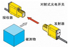
Working Principle of Through-Beam Photoelectric Switch
Notes:
1. Under normal circumstances, the light beam emitted by the transmitter has a certain angle. The receiver should be within the emission angle of the beam and at an appropriate distance; the output signal state of the receiver will be either high or low. If the output state of the receiver is abnormal, check whether the transmitter is aligned with the receiver or if the receiver is within the beam’s illumination range.
2. The power supply for photoelectric sensors is generally divided into AC and DC types. AC types are rarely used in inspection lines, while DC types are common, typically operating in the range of 10-30V, with 12V or 24V DC being standard.
3. The output method of photoelectric switches used in inspection lines is usually transistor-driven. It is important to distinguish between NPN and PNP transistor output methods, as the circuits for reading these two types of output signals differ, and incorrect connections will prevent normal signal reading.
2
Photoelectric Encoder Sensor
The photoelectric encoder is a sensor that converts the mechanical geometric displacement on the output shaft into pulses or digital quantities through photoelectric conversion. It is commonly found in chassis dynamometers or vehicle speed testers, primarily used for detecting roller speed.
The photoelectric encoder consists of a grating scale disk, a rotating shaft, and a photoelectric detection device. The grating scale disk has several rectangular holes evenly spaced on a circular plate of a certain diameter and is connected to the rotating shaft. When the rotating shaft is driven externally, the grating scale disk rotates, and the detection device, composed of a light-emitting diode and a photo-sensitive sensor, detects and outputs several pulse signals (see the working principle diagram). By calculating the number of pulses output by the photoelectric encoder per second, the current speed can be obtained.
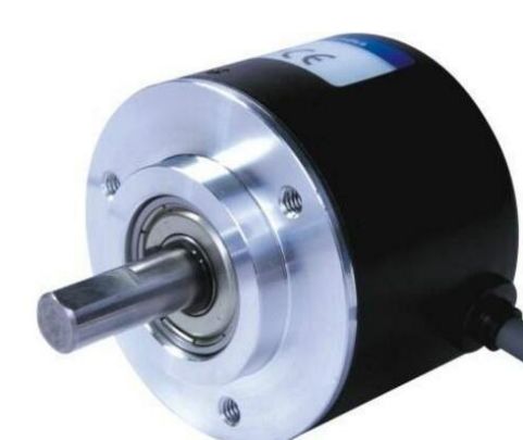
Photoelectric Encoder Physical Diagram
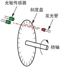
Working Principle Diagram of Photoelectric Encoder
Notes:
1. Generally, the photoelectric encoders used in platforms have low protection levels. To extend the sensor’s lifespan, avoid using the sensor when its surface is oily or wet.
2. Due to the precision of the internal structure of the sensor, avoid impacts and vibrations as much as possible.
3
Strain Gauge Pressure Sensor
The strain gauge pressure sensor, also known as a load cell, is a type of resistive pressure sensor that measures pressure values by detecting changes in resistance of strain gauges bonded to elastic elements. It is mainly used for measuring force, torque, weight, etc.
The basic principle of the strain gauge pressure sensor is the strain effect of resistance: when a conductor undergoes mechanical deformation, its resistance changes. Since temperature significantly affects resistance, the sensor typically requires temperature compensation to ensure measurement accuracy at different temperatures.
Below are two common types of strain gauge pressure sensors used in inspection lines.
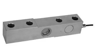
Beam-type Load Cell
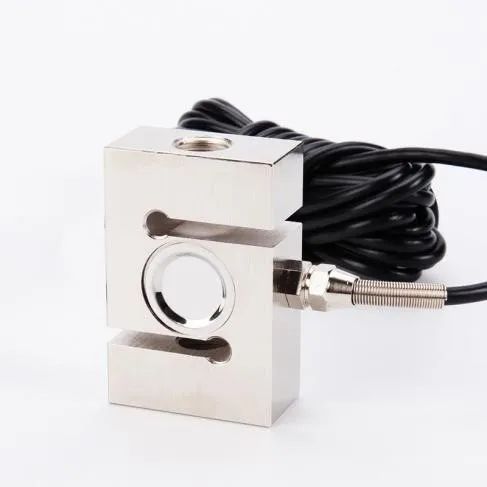
S-type Load Cell
Notes:
1. The load cells used in inspection lines mostly output differential signals, which have weak voltage signal variations and are easily affected by external interference. Generally, it is necessary to ensure that the sensor signal cables have shielding layers for protection, and the shielding layer must be effectively grounded.
2. To ensure the stability of the sensor signal, it is also necessary to ensure that the power supply output for the sensor is stable and has minimal fluctuations.
4
Differential Transformer Displacement Sensor
The differential transformer displacement sensor (LVDT) is manufactured using the principle of differential transformers, converting linear mechanical movement into changes in voltage, typically outputting a signal in the range of 0-5V. It is commonly found in side slip tables. The physical diagram is as follows:
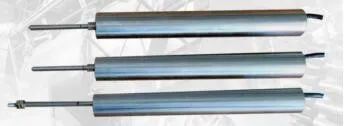
Physical Diagram of Sensor Used in Side Slip Table
Notes:
1. Displacement sensors typically use a single power supply, with a power supply range generally between 9-24V.
2. The signal output of displacement sensors is single-ended, and the voltage variation range is large. Generally, no amplifier is needed for signal amplification; it is sufficient to ensure that the power supply output for the sensor is stable, and to appropriately add filtering to the control system’s signal input to obtain stable and reliable displacement change data.
The four types of sensors mentioned above are commonly found in inspection lines. Different manufacturers may choose different models based on parameters such as linearity, sensitivity, drift, and repeatability. Regardless of the model chosen, the detection principles are generally similar.

Add WeChat: 18008470316 to apply for joining the Technical Exchange Group of the Inspection and Testing Industry Innovation Alliance!