Source: Bright Sun Circuits
Walking with you, being your most loyal supporter–– A new media integrated in the PCB industry– The most valuable circuit board industry service platform in 2024! We welcome your attention and likes! Wishing you success in your career! Peace and joy!
Embedded core boards are also known as SOM (Systems-on-Module) boards. A core board integrates the CPU and various peripherals, such as memory (DDR), storage (eMMC or FLASH), power management (PMIC), oscillators, etc. It also provides various interfaces like USB, GPIO, SPI, I2C, UART, Ethernet, PCIe, etc., to meet the needs of various applications.
A core board typically connects to a baseboard using board-to-board connectors, postage stamp hole soldering, gold fingers, COM Express, etc. It usually exposes all or most of the functional pins of the CPU, allowing users to design the circuit for functional interfaces based on application scenarios, thus reducing hardware development difficulty and saving development time.
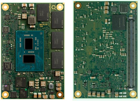 Intel Atom x6000E COM Express Core Board from: Congatec
SOMs are suitable for various industries, including industrial automation, medical devices, automotive electronics, communication systems, and the Internet of Things (IoT). Using SOMs can significantly shorten product development cycles, reduce overall costs, and improve product reliability.
Classification of Core Boards
To ensure the compatibility, modularity, and scalability of embedded core board hardware and software, different organizations or companies have defined several standards. The common embedded core board standards are as follows:
Open Standard Module (OSM)
OSM core boards are solderable LGA packaged modules with a compact size, the maximum size being 45mm x 45mm, and the module power is generally below 15W. They are very friendly for IoT applications and can meet low-cost and increasing performance demands.
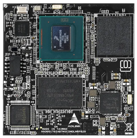 OSM standard IMX8MP Core Board from: ADLINK
Launched by NXP Semiconductors (formerly Freescale Semiconductor), this is a standard for embedded processor modules based on ARM architecture. The standard uses a 230-pin MXM gold finger design, facilitating high-speed I/O connections in handheld devices, HMI, and signage applications.
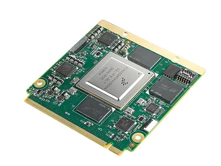 NXP i.MX 8QM Qseven Core Board from: Advantech
SMARC (Standard Module Advanced RISC Computer) is an open standard for defining embedded computer modules based on ARM architecture. It uses a 314-pin MXM gold finger connector, suitable for products requiring high performance and low power consumption.
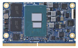
Intel Atom x7000 series (Amston Lake) Core Board from: ADLINK
Defined by PICMG (PCI Industrial Computer Manufacturers Group), this is a modular computer standard that supports multiple processor architectures, such as x86, ARM, and PowerPC. COM Express modules include Mini, Basic, and Compact sizes, which can be selected based on specific applications and power needs.
To adapt to next-generation AIoT applications, COM Express R3.1 has added multiple advanced interface supports including Type 6/7/10 with new PCIe Gen 4 interfaces, Type 6 modules have added USB 4.0 interfaces, and Type 7 modules have added a second PCIe Clock while upgrading 10G Ethernet to support CEI sideband signals.
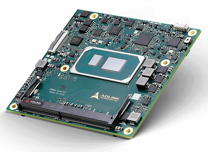
COM Express Type 6 11th Gen Intel Core i7 Core Board from: ADLINK
PCB Design for Embedded Core Boards
As embedded processors become more powerful and memory speeds increase, the number of PCB layers for embedded core boards has evolved from the early 4 layers to 8-12 layers. Due to the increasing number of high-speed interfaces, the requirements for board material loss are also becoming higher.
Generally, the following steps are followed for the PCB design of embedded core boards:
Determine Component Layout
Typically, the core board standard already specifies the standard outline and interfaces, so the layout of components will not vary much. The general approach is to follow the optimal fanout layout design according to the CPU’s reference manual, determine the layout of the CPU, DDR, and Flash, and then optimize the layout of the power supply and surrounding components.
Determine Board Thickness
The conventional PCB finished thicknesses are 0.5mm, 0.8mm, 1.0mm, 1.2mm, 1.6mm, 2.0mm, 3.2mm, 6.4mm, etc. The design standards for core boards usually specify the board thickness, and the design must comply with the corresponding requirements. For those without specified requirements, it can be made thicker from a structural reliability perspective.
Determine the Number of PCB Layers and Functional Layer Division
The total number of layers and the division of signal layers, power layers, and ground layers need to be considered from a systematic perspective, which is a compromise result. First, the number of layers must meet the wiring requirements; second, it must satisfy the routing requirements for high-speed signal lines; finally, consider power integrity, EMC, and thermal design requirements. Under the premise of meeting functionality, try to minimize the number of PCB layers.
Determine Inner and Outer Copper Thickness
When designing the stack-up, the thickness of the copper foil must be balanced to meet the current-carrying requirements of the power/ground plane layers. Copper thicker than 3oz is considered thick copper, commonly used in high-voltage, high-current power electronics products.
For signal layer copper thickness, the line width/spacing is relatively small, so the copper must be as thin as possible to meet the precise etching requirements. Due to the skin effect, high-speed signal lines flow only near the surface of the copper foil, so thicker copper foil does not yield better performance. Therefore, the copper thickness of the inner signal layers is usually Hoz, i.e., 0.5 ounces.
Determine Impedance Line Distribution
High-speed interface signal lines on core boards all have impedance requirements, commonly single-ended 50Ω, differential 100Ω, etc. Impedance control requires reference planes, and the copper thickness, dielectric constant, line width, and spacing will all affect impedance. When designing impedance lines, try to minimize the number of layers where impedance lines appear while meeting impedance requirements.
EDA tools support impedance calculations, and parameters can be adjusted according to the designed stack-up structure.
Most core boards, due to their high-density nature, will use blind vias and buried vias to optimize wiring space. However, blind vias and buried vias also increase the manufacturing difficulty of PCBs due to multiple laminations, making them more expensive.
During stack-up design, it is necessary to simplify the via structure as much as possible while meeting design requirements.
Select Board Materials, PP, and Copper Foil that Meet Design Requirements
FR-4 can meet the needs of most PCBs, is cost-effective, and has good electrical performance. High-speed PCBs will use high-speed materials, such as Panasonic’s Megtron4/6, etc. High-speed PCBs need to select dielectric materials with the lowest loss tangent and a small dielectric constant to meet the loss requirements for high-speed signals.
The roughness of copper foil (copper teeth) leads to uneven line width and spacing, resulting in uncontrollable impedance. Additionally, due to the skin effect, current concentrates on the surface layer of the conductor. The roughness of the copper foil surface affects the signal transmission length. When the signal frequency is below 5GHz, the influence of copper foil roughness is not significant, but above 5GHz, the effect becomes more pronounced, especially in designs for high-speed signals above 10GHz.
Note: The above copyright belongs to the original author. This account maintains neutrality regarding the article’s content. If there is any infringement or omission, please contact us for correction or deletion!

New media integrated in the PCB industry – being a valuable communicator

▲ For map inquiries/advertising cooperation/soft article publication, please add▲

▲ PCB Media WeChat Video Account▲

▲ PCB Media Douyin Video PCB SHOW▲
(Douyin ID: XCDH11)
Under the PCB industry integrated new media, covering WeChat public account/industry map/Douyin/video account/purchasing guide/exhibition meetings and other public platforms, fully cooperating with corporate product promotion/brand image marketing/dynamic information capture/data analysis reports/resource allocation integration/conference activity planning and other online and offline advertising services.


 Intel Atom x6000E COM Express Core Board from: Congatec
 OSM standard IMX8MP Core Board from: ADLINK
 NXP i.MX 8QM Qseven Core Board from: Advantech


