The methods are based entirely on the JJF 1587-2016 standard for the calibration of digital multimeters. I will elaborate on the parameters that customers generally need to measure and calibrate for multimeters.First, let’s understand the scope of this standard.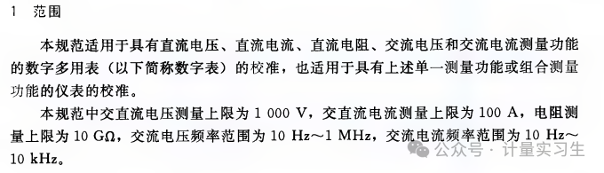 Understanding the scope of the standard.Classification of multimeter displays
For example, a 6.5-digit digital multimeter refers to a multimeter that can display ±1999999 (six and a half digits).
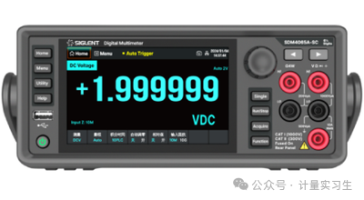
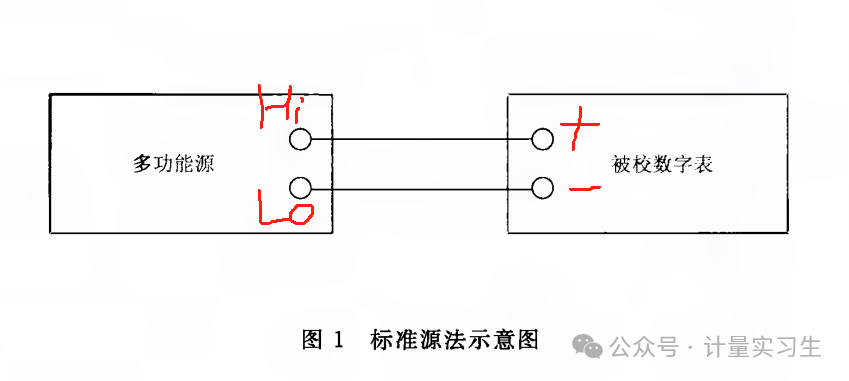
In digital multimeters, “digits” refer to the number of significant digits that can be displayed on the screen. Specifically, a 6.5-digit digital multimeter means it can display five full digits, and the sixth digit can show either 0 or 1. This representation comes from the resolution and accuracy of the multimeter.The calibration process for multimeters1. Verify basic information (customer, name, model specifications, factory number, management number, dial range). The range must be verified, as some manufacturers may have multiple ranges for the same model of multimeter. For example, the DC current range may include an additional 200uA current range. Therefore, it is essential to carefully check the dial range.2. Perform continuity testing to check if the fuses in the current A range and uA/mA range are blown. At this point, we will use the multimeter’s buzzer function to test continuity. Set our standard multimeter to the buzzer mode, connect the red and black probes correctly, and first short-circuit to see if there is a beep. A beep indicates continuity; otherwise, it is open. Then, connect the black probe to the COM of the multimeter being tested, and the red probe to the A range and uA/mA range of the multimeter to check continuity. If it is open, a maintenance request should be initiated as this multimeter does not meet calibration requirements. If it is not open, proceed to the next calibration step.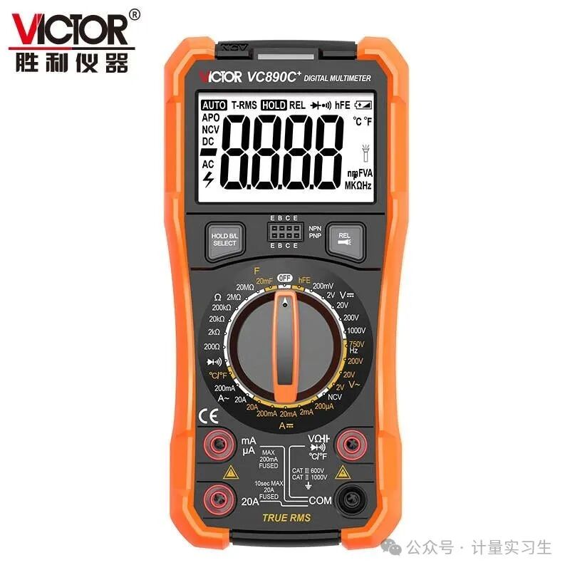 3. Calibration items (DC voltage, AC voltage, DC current, AC current, resistance)(1) Calibration of DC voltage, connect as shown in the figure below, paying attention to distinguish between positive and negative. Once connected, set the multimeter to the corresponding range. The multifunctional calibration source outputs the corresponding voltage value. The multifunctional calibration source is the standard value, while the multimeter shows the indicated value. If you find that the standard source method is not precise enough during measurement, you can also use the source meter method for measurement.
 In the source meter method, the standard value becomes the display value of the standard digital meter. For example, if the standard value is 10.00V, I need to continuously adjust the multifunctional source voltage output until the standard digital meter displays 10.00V. Then, record the voltage value of the multimeter being tested.
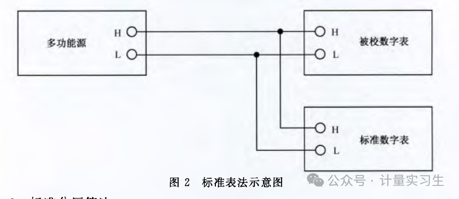 (2) The measurement method for AC current is the same, but the multifunctional source needs to add a frequency (generally, customers require calibration for AC voltage at 50Hz or 60Hz).(3) DC currentMeasuring current is slightly more challenging than measuring voltage; attention must be paid to the A range and uA/mA range, as well as the wiring and setting to the corresponding range. If not careful, it is easy to blow the fuse.
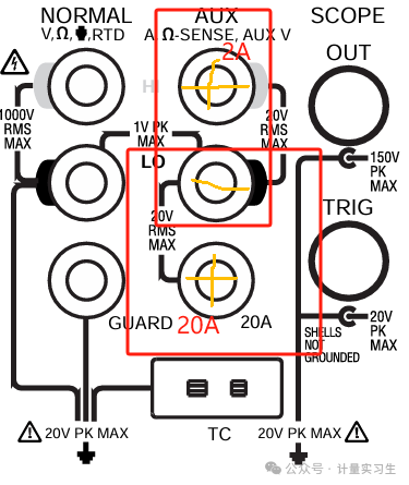
 It is also important to note that most multifunctional sources have two current output holes; the middle one is negative, the upper hole outputs 2A, and the lower hole outputs 20A.
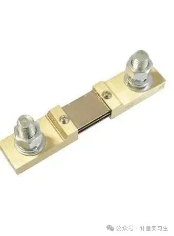
 Wiring follows the same standard source method as voltage.If you want to use the source meter method, you can connect a shunt in series to read the current. You can think of the shunt as a resistor, which will produce a voltage drop when current passes through.
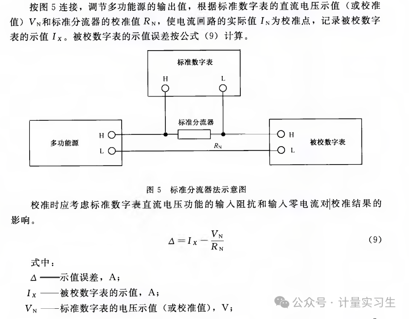 The measurement line is connected in series to the large screw of the shunt, and a voltmeter is connected in parallel to the two small screws of the shunt. If the specification of the shunt is 75mV/100A, it indicates that 1A produces a voltage drop of 1mV. Thus, with a current of 1A, a voltage of 1mV can be collected.
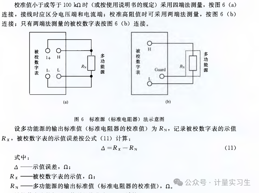
 (4) The measurement wiring for AC current is the same as for DC, but frequency must be added.(5) ResistanceResistance measurement wiring uses the standard source method, employing either a 4-wire or 2-wire measurement for resistance. The standard device can be a multifunctional source or a resistance box.
 The recalibration period is one year, and the customer requires the time to be specified in the certificate.
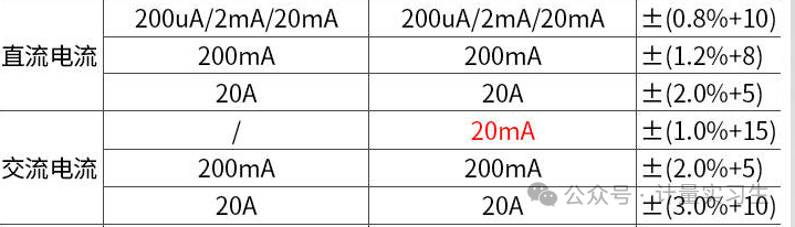
 Below is a specification for a multimeter.
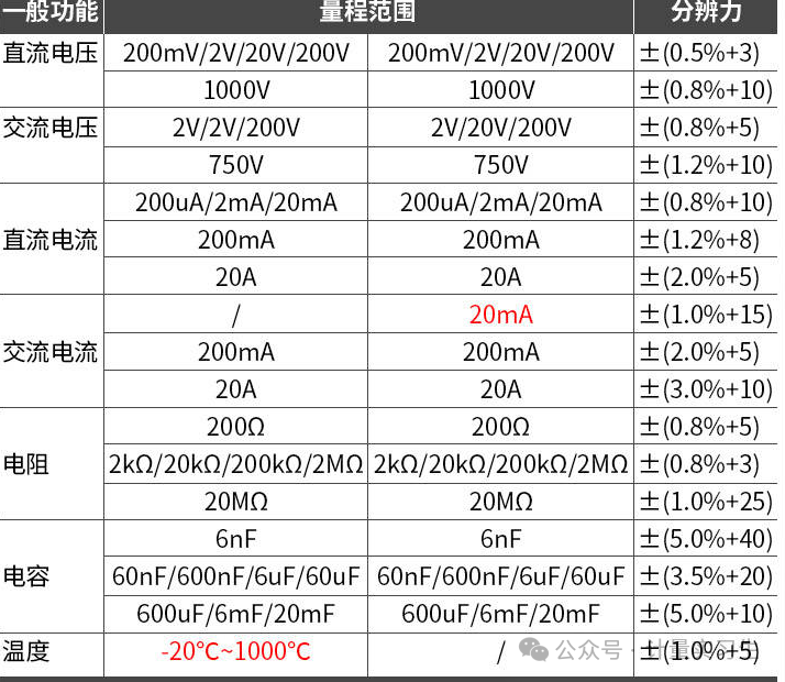 Multimeters can be said to be the instruments with the most data in electrical measurement. Therefore, we continuously measure and understand wiring, variations in errors, the basic changes in electricity, changes at different frequencies, trends in errors, the impact of uncertainty, and so on.